How to Choose a PCM or BMS for a Custom Battery Pack: Chemistry, Current, Protection, Balancing and Validation

Technically Reviewed By
Chief Scientist
Dr. Maximilian Weber is THOR Power’s Chief Scientist and a senior expert in lithium battery technology. His technical review focuses on battery safety, performance optimization, energy density and custom battery solution development.
Last technical review: September 2026

Written By
President of OEM Division & Custom Battery Specialist
Victor Xiong holds a Master’s degree from The Chinese University of Hong Kong, Shenzhen. He leads THOR Power’s OEM Division and focuses on custom battery solutions for global device brands, product developers and industrial customers.
| Written By | Technically Reviewed By |
|---|---|
| Victor Xiong President of OEM Division & Custom Battery Specialist. Victor Xiong leads THOR Power‘s OEM Division and focuses on custom battery development for global device brands, product developers and industrial customers. | Dr. Maximilian Weber Chief Scientist. Dr. Weber’s technical review for this article focuses on cell and topology matching, protection architecture, current and thermal paths, balancing, charging coordination, communication and production configuration control. |
Before choosing a PCM or BMS, an OEM team should define the battery chemistry, series count, current profile, charger behavior, temperature limits, communication needs and production evidence required by the final product. This guide helps product developers, engineers and sourcing teams avoid selecting a board by label alone. It builds on the Custom Battery Pack Design Guide as the parent workflow and the Series vs Parallel Battery Configuration Guide for topology.
A product team selected a board sold as a “4S 40A smart BMS.” The chemistry and nominal voltage appeared correct, the Bluetooth application displayed cell voltages and the bench load reached 40 A for several seconds. After the battery was installed, the motor startup caused nuisance trips, charging would not restart after a cold condition, and a firmware update changed the low-voltage recovery behavior without changing the board label.
The board was not necessarily defective. The project had approved a product name instead of a controlled protection and power-path architecture. It had not frozen the exact cell model, current waveform, thresholds, delays, temperature-sensor locations, charger behavior, recovery states, communication map or production configuration.
Quick Answer
Choose a PCM or BMS from the complete battery-system requirement, not from labels such as “12 V,” “4S” or “40 A.” Match the exact chemistry and series count first; then validate continuous and pulse current, voltage drop, heat, protection thresholds, temperature sensing, balancing, charger and device coordination, communication, recovery, firmware and production controls in the final product.
Four Approval Questions
1. Does the hardware and configuration match the exact cells and topology? 2. Can the complete cell-to-device current path carry every normal event without nuisance trips or excessive heat? 3. Do charger, device firmware and BMS protection boundaries coordinate through faults and recovery? 4. Can production repeat the approved hardware, settings, calibration and final-test result?
Case Transparency Note
The engineering cases in this article are representative composite scenarios based on recurring battery-project patterns. They explain selection and diagnostic decisions without identifying a specific customer or presenting confidential project data as a named THOR Power case study.
📥 Free OEM Resource
PCM/BMS Requirement Checklist
Freeze your chemistry, current, protection and production requirements before requesting a board recommendation.
1. BMS Selection Is a System Boundary Decision, Not a Board Purchase
A PCM or BMS acts only on the electrical and thermal conditions that it measures and the current paths that it controls. It cannot correct a charger with the wrong voltage, a cell with insufficient pulse capability, an unsuitable connector and wire configuration that overheats below the electronic trip point, a device cutoff that conflicts with the pack, or parallel modules that were never designed for controlled current sharing.
The useful engineering question is not “Which BMS has enough amps?” It is “Which sensing, decision, switching and recovery architecture keeps every cell, conductor and operating state inside the approved limits of the complete product?”
Core Engineering Principle
Protection is an abnormal-condition boundary, not the normal operating strategy. The charger, device firmware and power path should control routine operation inside the validated cell limits. The PCM or BMS should intervene when an abnormal condition crosses a defined threshold and should recover only in a controlled, verified way.
A BMS is not one component. It is a chain of cell sensing, current sensing, temperature sensing, decision logic, switching, balancing, gauging, communication, fault containment, recovery and configuration control. A failure or ambiguity in any link can invalidate the complete protection function.
2. PCM vs BMS: What Is the Difference?
PCM usually refers to a compact protection circuit module that provides essential overcharge, overdischarge, overcurrent and short-circuit protection. BMS is a broader term that may add per-group monitoring, balancing, temperature logic, current measurement, state estimation, communication, contactor control, precharge and fault logging. Supplier terminology is inconsistent, so the approved specification must list functions and settings rather than rely on the product name.
| Decision area | PCM direction | BMS direction |
|---|---|---|
| Typical project | Single-cell or compact low-series pack with limited system interaction. | Multi-series, high-power, connected, serviceable or module-level system. |
| Core protection | Overcharge, overdischarge, overcurrent and short circuit; sometimes one NTC input. | Configurable cell, pack, current and temperature protection with defined delays and recovery. |
| Cell monitoring | Minimum channels needed for protection. | Per-series-group measurement, diagnostics, open-wire checks and plausibility functions. |
| Balancing | Absent or simple passive balancing. | Passive or active balancing with defined enable windows, current and thermal limits. |
| SOC and SOH | Usually absent. | Fuel gauge, learned capacity/resistance, runtime estimate or host-reported data. |
| Communication | Usually none. | UART, SMBus, I2C, CAN, RS485 or a controlled proprietary protocol. |
| Switching | Back-to-back MOSFETs, common or separate port. | Parallel MOSFETs, contactors, precharge, isolation and module coordination may be required. |
| Approval basis | Thresholds, current path, standby current and final-device behavior. | Hardware, settings, calibration, firmware, communication, logs and production controls. |
A single-cell custom LiPo battery may need only a compact PCM, NTC and correctly matched charger. A 16S LiFePO4 backup module may need per-cell monitoring, current measurement, multiple temperature sensors, balancing, contactors, precharge, communication and fault records. Calling both products a “BMS” does not make them technically equivalent.
3. Freeze the Battery-System Requirement Before Supplier Selection
A protection board cannot be selected reliably from chemistry, nominal voltage and a current label alone. The requirement must connect cell limits, load behavior, charger states, product firmware, mechanical integration, environmental conditions and production evidence. Use the PCM/BMS Requirement Checklist before requesting a board recommendation. Record the assumptions before the supplier sees the test result; otherwise settings can be adjusted after a failure without a clear approval basis.
| Requirement group | Information to freeze | Why it changes the PCM/BMS |
|---|---|---|
| Cells and topology | Manufacturer, model, chemistry, series-parallel arrangement, lot strategy and cell operating limits. | Defines channel count, voltage window, current per cell, balancing need and charger settings. |
| Product load | Battery-side continuous, pulse, startup, stall, regenerative and fault current with duration and repetition. | Defines switch path, delay settings, thermal test and ride-through versus trip behavior. |
| Charger and power path | Charge voltage/current, source limits, termination, operation while charging, dead-battery behavior and restart. | Defines charge FET direction, recovery, overvoltage margin and charger-BMS coordination. |
| Device firmware | Normal shutdown, undervoltage lockout, wake, sleep, fault handling, retry timing and data retention. | Determines whether protection is a backup boundary or the routine control mechanism. |
| Temperature and mechanics | Ambient range, enclosure, heat sources, sensor locations, airflow, potting, vibration and service. | Controls sensor quantity, thresholds, thermal rise and installation reliability. |
| Communication and service | Protocol, data map, update rate, scaling, fault memory, field diagnostics and access control. | Defines smart-BMS architecture, firmware ownership and integration evidence. |
| Compliance and production | Target markets, standards, transport route, production volume, test limits and change notification. | Determines documentation, configuration control, pilot validation and substitution rules. |
Requirement Warning
Do not allow the current rating, threshold, sensor location or pass/fail rule to be defined only after a sample fails. Agree the waveform, ambient, enclosure, sensor points, delays, recovery and acceptance criteria before the test.
4. Eight Engineering Gates for Choosing a PCM or BMS
The eight gates below convert a general board request into a controlled battery-management architecture. A board that fails any one gate can make the complete pack unsuitable even when nominal voltage and advertised current appear correct.
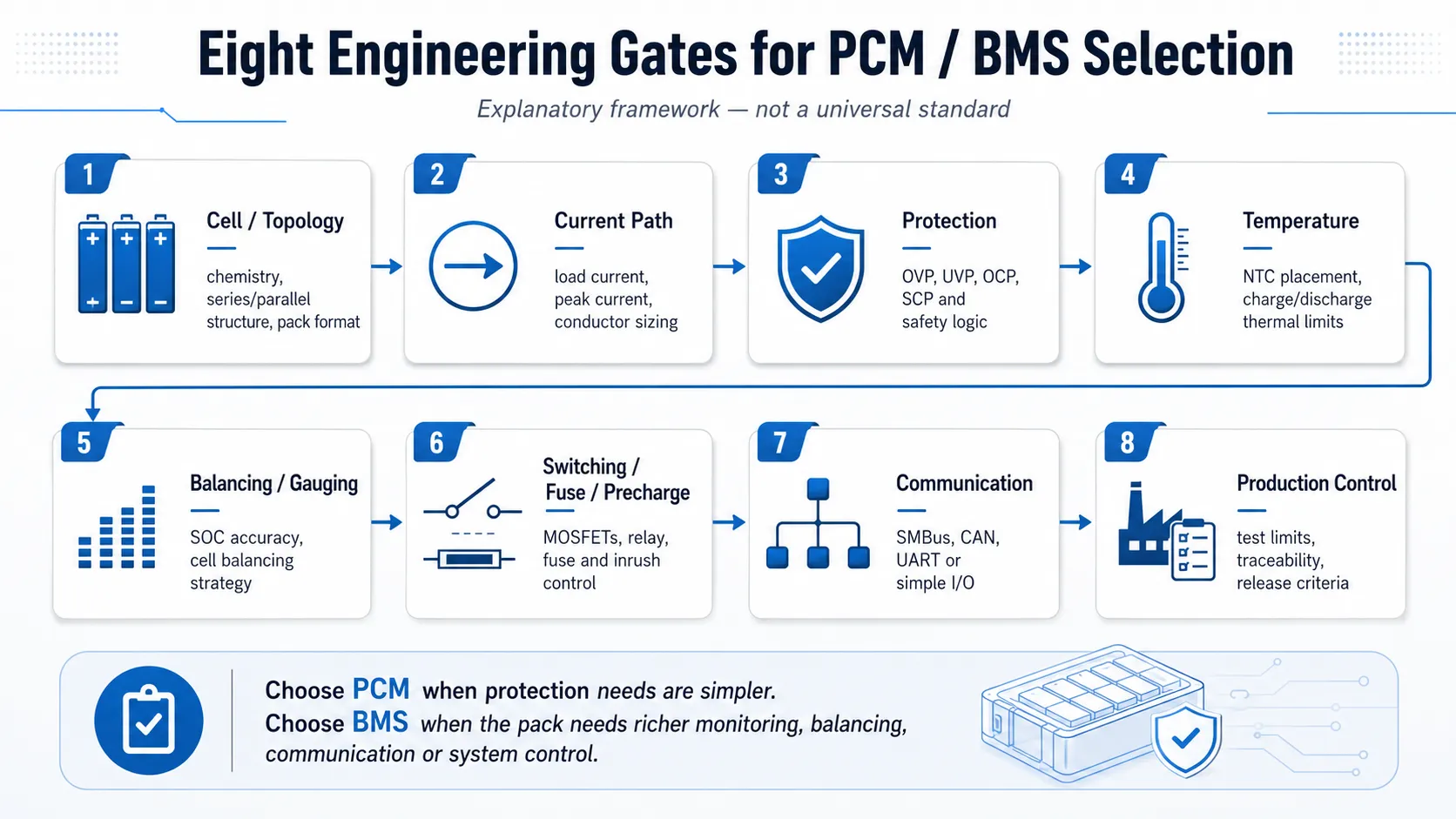
| Gate | Engineering decision | Release evidence |
|---|---|---|
| 1 — Cell and topology match | Match exact cell chemistry, model, series count and parallel architecture. | Approved cell data, voltage window, topology drawing and charger basis. |
| 2 — Current and power path | Define continuous, peak, inrush, stall, regenerative and fault events. | Measured waveform, time-current requirement, resistance and thermal evidence. |
| 3 — Protection coordination | Set voltage, current, temperature, delay, hysteresis and recovery boundaries. | Controlled setting table linked to charger and device behavior. |
| 4 — Temperature sensing | Place sensors where they represent charge, discharge and power-path limits. | Sensor specification, installation drawing, fault response and thermal validation. |
| 5 — Balancing and gauging | Select balancing and state estimation from the real mismatch and user need. | Balance budget, gauge model, learning/calibration and end-of-discharge evidence. |
| 6 — Switching and fault containment | Select ports, FETs/contactors, precharge, fuse and module coordination. | Schematic, trip curves, inrush test, fault containment and recovery logic. |
| 7 — Communication and service | Define protocol, data ownership, fault memory, wake/sleep and field behavior. | Interface control document, logs, firmware tests and service rules. |
| 8 — Production configuration | Freeze hardware, settings, firmware, calibration and final-test limits. | Traceable sample, controlled files, pilot-lot data and change matrix. |
5. Gate 1: Match the Exact Chemistry, Cell Model and Series Count
The first gate is the exact cell manufacturer, model, chemistry and number of series groups. “4S” describes series count, not the approved voltage window. A 4S pack using common 3.6/3.7 V nominal lithium-ion cells is often 14.4-14.8 V nominal and 16.8 V at full charge, depending on the cell datasheet. A 4S LiFePO4 pack is commonly 12.8 V nominal and uses a different charge and protection window. Some battery monitors support Li-ion, Li-polymer and LiFePO4 hardware platforms, but the thresholds and behavior still have to be configured for the exact cell and application.
| Selection input | Why a generic label is insufficient | Required evidence |
|---|---|---|
| Cell chemistry and model | Cells with the same nominal chemistry can have different charge limits, discharge limits, current and temperature rules. | Manufacturer datasheet, approved part number and lot/change policy. |
| Series count | The same “12 V,” “24 V” or “48 V” product label can represent different chemistries and series counts. | Series-group drawing, nominal/full/minimum voltage and charger output. |
| Parallel count | Parallel cells change current per cell, fault energy, current sharing and sensing assumptions. | Topology, interconnection geometry, cell matching and branch/group tests. |
| Sense wiring | A correct IC setting cannot protect a cell group that is measured incorrectly. | Pinout, wire routing, open-wire response and end-of-line verification. |
| Cell replacement | A similar capacity does not prove equivalent loaded voltage, charge behavior, thermal performance or compliance scope. | Formal substitution review and affected revalidation plan. |
Composite Engineering Case 1 — The Misleading 12 V Label
Project situation: A buyer requested a “12 V, 4S BMS” for a portable instrument.
Hidden risk: The intended pack was 4S LiFePO4, but the proposed board and charger used a conventional 4S lithium-ion voltage window. Series count matched; chemistry and charge limits did not.
Engineering response: The team froze the exact cell model, full-charge voltage, device cutoff, BMS thresholds, recovery and charger profile before selecting the board.
Buyer lesson: Nominal system voltage is not a protection specification. Chemistry, exact cell and series count must be approved together.
6. Gate 2: Calculate the Real Continuous and Peak Current Envelope
For a regulated or approximately constant-power load, the highest normal battery current can occur near the minimum operating voltage. When only load-side power is known, a first estimate is Ibatt ≈ Pload / (Vbatt,min × ηpower-path). If battery-side current has already been measured, do not divide by efficiency again. Constant-current, motor and pulsed loads should use the measured battery-side waveform rather than a forced constant-power model.
The requirement should separate continuous, RMS, peak, inrush, stall, regenerative and abnormal current. Each event needs amplitude, duration, repetition, state of charge, temperature and the intended response: ride through, derate, limit or disconnect. A board current label may describe a laboratory limit, a short pulse, unusually strong cooling or only the MOSFET rating. It does not prove that the complete cell-to-device path can carry the same current. Use the Battery Runtime Calculation Guide for the load and energy model.
Current and Heat Check
For a simplified path resistance Rpath, voltage drop is ΔV = I × Rpath and conduction loss is Ploss = I² × Rpath. At 50 A through 6 milliohms, the instantaneous drop is 0.30 V and the loss is 15 W. At 30 A, the same path dissipates 5.4 W. Thermal acceptance still depends on duration, repetition, copper area, enclosure, airflow and starting temperature.
| Load condition | Data required | Approval check |
|---|---|---|
| Continuous load | Battery-side sustained or RMS current at minimum operating voltage and maximum ambient. | Cell, MOSFET, shunt, fuse, busbar, wire and connector temperature rise. |
| Peak or pulse | Amplitude, duration, repetition, state of charge and temperature. | Protection delay, voltage sag, cell pulse limit and recovery. |
| Motor stall or inrush | Worst credible event, not only a normal successful start. | Whether the BMS should ride through, limit or disconnect without damage. |
| Regenerative current | Direction, amplitude, duration, pack SOC and charger/load state. | Charge path capability, overvoltage margin and system coordination. |
| Cold or aged pack | Higher resistance, lower loaded voltage and end-of-life requirement. | Premature cutoff, extra heating and device reset risk. |
| Fault current | Available source energy, path impedance and protective-device sequence. | Electronic trip, fuse/contactors, conductor withstand and safe post-fault condition. |
Composite Engineering Case 2 — Average Current Passed, Motor Start Failed
Project situation: A motorized product drew 18 A during normal operation but reached about 70 A for 300 ms at startup.
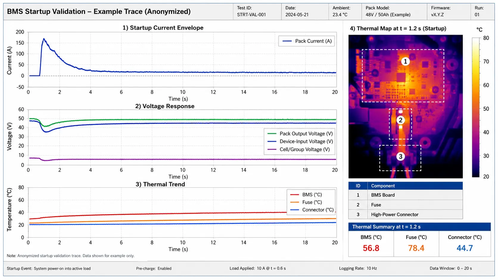
Hidden risk: A board sold as 40 A passed a steady bench load, yet its overcurrent threshold and delay opened during startup. The low-SOC cell voltage and connector drop also reduced the margin.
Engineering response: Approval was separated into an 18 A continuous thermal test and a 70 A / 300 ms ride-through event. The team captured cell voltage, pack output, device input and current, then verified cell pulse capability, BMS delay, current path and controlled recovery.
Buyer lesson: A current label cannot approve a waveform. Continuous thermal performance and short-event behavior are different tests.
How many amps should the BMS be? Choose the BMS current capability from the measured continuous, peak, inrush, stall and regenerative envelope at the minimum battery voltage and worst expected temperature. Then verify the cells, MOSFETs, shunt, fuse, interconnections, wire, connector and enclosure as one thermal current path. A fixed percentage of headroom is not a substitute for time-current and thermal evidence. For cylindrical motor and peak-current packs, see 18650 / 21700 battery packs.
7. Gate 3: Coordinate Protection Thresholds With the Charger and Device
A protection threshold is incomplete without its delay, hysteresis or release condition, recovery method and product response. Review cell overvoltage, cell undervoltage, charge and discharge overcurrent, short circuit, charge and discharge temperature, sensor faults, open-wire behavior and any secondary-protection function as a coordinated set.
Normal charging should terminate inside the approved cell window before BMS overvoltage protection. Normal product shutdown should occur before deep BMS undervoltage protection. The protection layer remains available for abnormal operation instead of becoming the routine charge or end-of-runtime controller.
| Function | Normal system control | BMS protection boundary | Recovery evidence |
|---|---|---|---|
| High cell voltage | Charger regulates CC/CV and terminates below the cell maximum with tolerance. | Cell overvoltage threshold, delay, release and charge-path state. | Restart behavior, charger interaction, cell balance and no repeated boundary cycling. |
| Low cell voltage | Device reduces load or shuts down with time to save data. | Cell undervoltage threshold, delay and discharge-path state. | Load removal, charger-assisted or controlled wake recovery without unsafe cell stress. |
| Overcurrent | Product limits normal startup, stall or peak demand where possible. | Charge/discharge thresholds and delays matched to the real waveform. | No nuisance trip in normal use; deterministic recovery after abnormal use. |
| Temperature | Charger/device derates or stops before hardware limits where required. | Separate charge/discharge thresholds, delays and sensor-fault behavior. | Predictable enter/exit behavior and no uncontrolled retry loop. |
| Communication fault | Host uses valid data, timeouts and safe fallback states. | BMS fault handling, output state and logging where supported. | Controlled reconnect, version compatibility and retained diagnostic evidence. |
Composite Engineering Case 3 — Protection Worked, Product Behavior Failed
Project situation: A data-logging device operated until the BMS opened on deep undervoltage.
Hidden risk: The cells were protected, but the product lost unsaved data and required charger connection before the pack output recovered.
Engineering response: The device shutdown threshold was raised, the firmware reserved controlled shutdown time, and the BMS undervoltage setting remained a secondary safeguard. Loaded low-SOC testing was repeated at cold temperature and with an aged-pack margin.
Buyer lesson: A safe cell cutoff can still produce an unacceptable product failure. Approve system behavior before, during and after protection.
8. Gate 4: Define Temperature Sensing by Function and Location
A temperature input is useful only when the sensor type and placement, thresholds, delays, tolerance and failure response are defined. Charging and discharging may have different temperature boundaries. The coldest cell can control whether charging is allowed, while the hottest component during discharge may be a cell group, MOSFET, shunt, fuse, busbar or connector. Compact packs may use one NTC when the thermal field is simple and validated. Larger, sealed or high-power packs may need several cell and power-path sensors.
| Sensor question | Weak assumption | Required validation |
|---|---|---|
| What is being protected? | One NTC represents every cell and power component. | Map cell groups, BMS, fuse, busbars, connector and external heat sources under the real duty cycle. |
| Where is the limiting cold point? | Room temperature represents cell temperature during charging. | Cold soak, thermal lag, sensor tolerance and charger/firmware response. |
| How is the sensor installed? | The drawing position guarantees thermal contact. | Adhesive, pressure, insulation, routing, vibration and after-test inspection. |
| What happens on sensor open or short? | Invalid readings will always be recognized. | Diagnostic ranges, charge/discharge permissions, fault code and recovery after repair. |
| How many sensors are enough? | More sensors automatically improve safety. | Each sensor must have a defined decision function, threshold and production test. |
Sensor Placement Rule
Place and validate sensors for the failure or control condition they must detect. A precise sensor at the wrong location can produce a precise but irrelevant measurement. For the full sensing and current path, see the Connector, Wire & PCM/BMS Customization review.
9. Gate 5: Choose Balancing and Gauging From the Actual Requirement
Passive balancing removes charge from higher-state cells, usually through bleed resistors. Active balancing transfers energy between cells or modules. Neither method repairs a weak cell, reverses capacity loss, lowers abnormal resistance or replaces cell matching. Balancing is a state-equalization tool with finite current, time and thermal availability.
Balance-Time Estimate
A first estimate is balance time ≈ charge mismatch / available balance current. A 0.5 Ah mismatch with 50 mA balancing requires about 10 ideal hours. If balancing is enabled only near full charge, interrupted by temperature limits or shared among channels, actual correction takes longer.
| Observed condition | Engineering direction | What must be verified |
|---|---|---|
| Well-matched small or medium pack | Passive balancing may be sufficient or balancing may not be needed on every architecture. | Expected drift, threshold, current, temperature and charge-window availability. |
| Large series stack with small recurring SOC drift | Passive or active depends on energy, downtime, heat and service value. | Mismatch rate, service interval, recovered energy and system-level benefit. |
| Large difference caused by capacity or resistance | Balancing alone is not the corrective action. | Group diagnostics, cell matching, replacement criteria and root cause. |
| Parallel modules | Module SOC, current sharing, isolation and communication may matter more than cell-only balancing. | Connection sequence, voltage difference, reverse current, module limits and fault coordination. |
Composite Engineering Case 4 — The Balance-Current Label Hid a Weak Group
Project situation: Controlled cycling showed that one series group reached its voltage boundary about 2 Ah earlier than the strongest group.
Hidden risk: A 50 mA passive balance path would require roughly 40 ideal hours to move 2 Ah, and it could not restore the limiting group. One instantaneous voltage reading would not have proven the capacity difference.
Engineering response: The team used controlled charge/discharge data, resistance checks and group traceability to identify the weak group, then reviewed cell matching and replacement criteria instead of extending the balance timer.
Buyer lesson: Balancing can reduce state difference; it cannot convert a weak group into a healthy one.
Fuel gauging and runtime reporting need their own approval. Voltage-only state-of-charge estimates are limited under dynamic load and in flat-voltage chemistries. Coulomb counting can drift, and model-based gauging depends on cell profile, temperature, load and learned capacity or resistance. Define the required accuracy, operating states, learning procedure, full/empty qualification, end-of-discharge behavior and host interpretation. A smart BMS also creates a standby-power budget. Measure quiescent current, ship mode, wake sources, balancing standby behavior and long-storage recovery for products that may sit unused for weeks or months.
10. Gate 6: Match the Switching Architecture, Precharge, Fuse and Module Power Path
The switching path may use common-port or separate-port MOSFETs, high-side or low-side switching, parallel FETs, relays or contactors. The correct direction depends on charger connection, load grounding, regenerative current, recovery, isolation, service and whether charge and discharge must be controlled independently.
A BMS does not replace the charger. The charger regulates the chemistry-specific profile; the BMS monitors and blocks operation when protection limits are crossed. Dead-battery handling, temperature qualification, charge termination and operation while charging still require a suitable charger and final-device validation.
Precharge is a voltage-matching process. Precharge limits the initial current into inverter, motor-controller or DC-link capacitance before the main current path closes. A first estimate is Iinitial = ΔV / Rprecharge, while the capacitor rise follows the RC time constant τ = Rprecharge × CDC. For a 48 V battery and a 100 ohm precharge resistor connected to an initially discharged DC link, the initial current is about 0.48 A and the initial resistor power is about 23 W. Main-contactor closure should follow a verified downstream-voltage or voltage-difference criterion, not only an arbitrary delay.
Electronic protection and fuse coordination. Electronic overcurrent protection depends on current measurement, configured delays, gate drive and switching devices. A fuse is a separate passive protective element that does not depend on firmware or normal gate-drive operation. The two should be coordinated rather than treated as interchangeable. Review the BMS trip behavior and switch capability against fuse time-current behavior, system voltage, available fault current, conductor withstand, connector limits, ambient and component placement.
| Architecture choice | Use when | Evidence needed |
|---|---|---|
| Common-port MOSFET path | Charge and discharge share the same external connection and control behavior is compatible. | Current direction, charger presence, recovery, reverse current and thermal test. |
| Separate-port path | Charge and discharge require different current paths or independent control. | Pinout, grounding, charger/load states, fault direction and service behavior. |
| Parallel MOSFETs | Current and heat exceed one-device capability. | Current sharing, gate timing, thermal symmetry, failure behavior and controlled component set. |
| Contactors | Voltage, current, isolation or service requirements exceed compact FET architecture. | Coil control, weld detection, opening under load, precharge and safe state. |
| Precharge circuit | Downstream capacitance can cause inrush or false short-circuit detection. | Initial current, voltage rise, resistor energy, timing, retries and failed-precharge response. |
| Fuse or secondary protection | Independent passive containment is required by hazard analysis or system energy. | Interrupt rating, time-current coordination, conductor withstand and replacement/service rule. |
| Parallel pack modules | Capacity or redundancy requires multiple independently protected modules. | Voltage matching, current sharing, reverse-current control, isolation, communication and reconnect rules. |
Composite Engineering Case 5 — The Missing Precharge Function
Project situation: A LiFePO4 module was connected to equipment with a large input capacitor.
Hidden risk: The initial charging current into the DC link was interpreted as a short circuit or severe overcurrent event, causing repeated BMS trips and contactor retries.
Engineering response: The design added a controlled precharge path, verified the downstream voltage before main closure and defined timeout, retry and failed-precharge behavior. Fuse and contactor coordination were reviewed at the same time.
Buyer lesson: A higher BMS current label does not solve uncontrolled capacitance inrush. The connection sequence is part of the battery architecture.
11. Gate 7: Define Communication, Fault Memory and Service Behavior
Communication is valuable only when the protocol, data meaning, update timing, scaling, validity, ownership and failure response are controlled. A Bluetooth screen that displays voltage is not an interface specification. The host device and service team need to know which data can control operation and which data are diagnostic only.
| Interface item | Requirement to define | Validation question |
|---|---|---|
| Protocol and physical layer | UART, SMBus, I2C, CAN, RS485 or proprietary interface; voltage levels, isolation and termination. | Does the final harness and host communicate reliably across voltage, temperature and fault states? |
| Data map and scaling | Cell/pack voltage, current, temperature, SOC, SOH, alarms, units, resolution and valid range. | Does the host interpret every field correctly, including signed current and unavailable data? |
| Timing and timeouts | Update rate, startup order, sleep, wake, heartbeat and stale-data handling. | Does the product enter a defined safe state if messages stop or arrive late? |
| Commands and permissions | Charge/discharge enable, ship mode, reset, configuration access and service authorization. | Can an unintended command bypass the approved operating boundary? |
| Fault memory | Event code, timestamp or cycle count, freeze-frame data, clearing and retention. | Can a field failure be reconstructed without erasing the evidence during recovery? |
| Version control | Firmware, configuration, host compatibility and change notification. | Can production and service identify the exact approved version on a physical unit? |
Communication Boundary
A smart BMS should fail predictably when communication is missing, delayed or invalid. The host must not assume that a missing message means the battery is healthy, empty or safe to charge.
12. Gate 8: Freeze Hardware, Firmware, Settings and Production Evidence
For a configurable BMS, the setting file, firmware, calibration, communication map and manufacturing test are part of the battery design. Replacing the monitor IC, MOSFETs, shunt, NTC, connector, cell or firmware can change measurement accuracy, protection timing, heating, balancing, recovery and compliance scope. A sample is not production-equivalent unless the approved BOM, configuration file, firmware version or hash, calibration method and final-test limits remain tied to the physical unit.
| Controlled item | Why it matters | Minimum production control |
|---|---|---|
| Monitor/protector IC and PCB revision | Measurement range, protection features and sense routing can change. | Approved manufacturer part number, board revision and incoming/first-article checks. |
| MOSFETs, contactors and shunt | Loss, current measurement, switching and fault behavior change. | Approved parts, solder/weld process, calibration and thermal/current test. |
| Firmware and configuration | Thresholds, delays, balance logic, wake/sleep and communication can change invisibly. | Version/hash, protected master file, programming verification and audit trail. |
| NTC and sensing assembly | Location, beta value, contact and wiring determine temperature decisions. | Drawing, approved materials, installation inspection and fault test. |
| Cell, topology and harness | Voltage sag, current sharing, heat and protection margins change. | Approved BOM, lot traceability, drawings and loaded functional test. |
| Final-test limits | A generic PASS result may not verify the approved behavior. | Measurement method, calibrated fixture, numeric limits, raw record and unit identity. |
| Engineering changes | An “equivalent” part can invalidate performance or certification evidence. | Notification route, impact review, revalidation matrix and customer approval where required. |
Composite Engineering Case 6 — The Sample Passed, the Production Settings Changed
Project situation: A configurable smart BMS passed prototype testing and final-device integration.
Hidden risk: During pilot production, a different configuration file was loaded to simplify programming. The board part number remained unchanged, but undervoltage recovery, sleep current and balance enable conditions changed.
Engineering response: The release package added a controlled configuration checksum, programming verification, sample traceability, final functional limits and a change-approval rule. The pilot lot was retested with the production file.
Buyer lesson: For a configurable BMS, settings are hardware in functional terms. A board label cannot prove production equivalence.
Need the PCM/BMS Selection Checked Against the Real System?
Send the cell chemistry and series count, load waveform, charger behavior, temperature limits, communication needs and fault-recovery requirements. THOR Power can review thresholds, switching architecture, sensing, balancing and production settings before release.
13. What a PCM or BMS Can — and Cannot — Protect
| Risk or function | What the PCM/BMS can do | What it cannot replace |
|---|---|---|
| Cell overvoltage/undervoltage | Measure every series group and disconnect or report when configured limits are crossed. | Correct charger regulation, accurate sense wiring or a normal device shutdown strategy. |
| Charge/discharge overcurrent | Act within measurement range, delay and switching capability. | A cell, connector, wire or weld that overheats below the trip threshold. |
| Short circuit | Disconnect under defined detection, delay and available-fault conditions. | Unlimited interrupt capability, arc containment or every external short scenario. |
| Temperature | Act on measured sensor locations and configured thresholds. | Hot spots with no sensor, poor sensor contact or an enclosure that traps heat. |
| Cell imbalance | Reduce state difference within available balance current and time. | Capacity loss, high resistance, internal defect or severe mismatch. |
| Remaining runtime | Estimate SOC/runtime when the gauge is correctly configured and learned. | Guaranteed product runtime without duty-cycle, aging and cutoff validation. |
| Charging | Allow, block or communicate charge conditions. | A chemistry-appropriate charger and correct termination. |
| Fuse/containment | Coordinate electronic switching with additional protective elements. | Independent passive interruption when the architecture requires it. |
| Certification | Serve as one evaluated safety element of a defined pack. | Automatic compliance of the battery, charger, host product or future substitutions. |
14. Validate the Production-Intent PCM or BMS in the Final Battery Pack
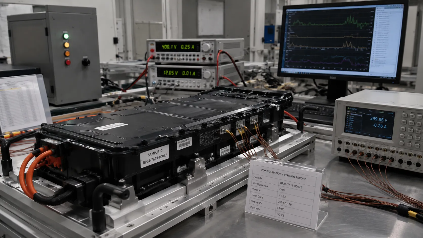
Bench communication with an evaluation board is not final validation. Test the production-intent cells, BMS hardware, configuration, fuse, interconnections, connector, wire, enclosure, charger and device firmware as one system. Acceptance criteria should define the product behavior before, during and after every relevant threshold or fault. Every sample should have a traceable ID linked to the cell lot, PCB revision, component set, firmware/configuration, calibration, harness, NTC locations, charger, device firmware and prior test exposure.
| Validation area | Representative test | Approval evidence | Typical owner |
|---|---|---|---|
| Configuration | Verify cells, topology, BOM, board revision, firmware, settings and calibration. | As-built record, photos, checksum/version and sample ID. | Supplier + OEM |
| Cell voltage measurement | Compare every channel with calibrated references across the operating range. | Accuracy, channel consistency, sense-wire and open-wire results. | Supplier |
| Current measurement/path | Continuous, peak, inrush, stall, regenerative and fault waveforms. | Synchronized current/voltage, temperature and no nuisance trip. | Supplier + OEM |
| Voltage protection | Cross overvoltage/undervoltage thresholds under controlled conditions. | Trip, delay, hysteresis, release and product recovery. | Supplier + OEM |
| Temperature protection | Hot/cold operation and sensor open/short simulations. | Permissions, delays, diagnostics and recovery match requirements. | Supplier + OEM |
| Balancing and gauging | Enable window, current, thermal behavior, convergence and SOC accuracy. | Raw data, mismatch correction, learning/calibration and error bounds. | Supplier + OEM firmware |
| Charger coordination | Precharge, CC/CV, termination, restart, low temperature and charge-while-use. | Charge traces, temperatures, BMS state and stable product behavior. | OEM + supplier |
| Communication | Startup, sleep/wake, timeouts, invalid data, commands and fault memory. | Protocol logs, safe fallback and version compatibility. | OEM firmware + supplier |
| Mechanical/thermal | Final enclosure, cable route, vibration, repeated duty and adjacent heat sources. | Before/after data, inspection and installed thermal evidence. | OEM + supplier |
| Pilot production | Sample across normal tools, operators, cells and programming process. | Lot data, critical-to-quality checks and final-test records. | Supplier quality + OEM |
Safety Boundary
Short-circuit, overcharge, forced-discharge, crush, impact or other hazardous abuse testing must use the applicable standard, trained personnel, approved fixtures, instrumentation and containment. A blog article is not an abuse-test procedure.
15. Common OEM Mistakes When Choosing a BMS
| Mistake | Why it fails | Better approval rule |
|---|---|---|
| Selecting from “12 V” and “40 A” | Nominal labels omit chemistry, cell limits, delays, heat and recovery. | Approve exact cells, topology, waveform, settings and final-device evidence. |
| Using one configuration for Li-ion and LiFePO4 | Series count can match while charge and protection windows differ. | Freeze chemistry-specific configuration and charger coordination. |
| Treating MOSFET rating as pack current rating | Cells, shunt, PCB, fuse, busbars, wire and connector can limit first. | Validate the complete current path thermally and dynamically. |
| Checking average current only | Startup, stall, transmit, compressor and regenerative events can trip or reset. | Capture amplitude, duration, repetition, state of charge and temperature. |
| Using protection as normal control | Routine hard trips create data loss, poor UX and boundary cycling. | Coordinate charger regulation and device shutdown inside protection limits. |
| Expecting balancing to repair a weak group | Finite balance current cannot restore capacity or resistance. | Diagnose groups, matching, assembly and replacement criteria. |
| Ignoring NTC installation and sensor faults | A correct threshold with poor contact or wrong location is ineffective. | Validate sensor function, placement, open/short response and production assembly. |
| Paralleling protected packs without system design | Voltage difference, reverse current and protection interaction can be unstable. | Define precharge, current sharing, isolation, communication and reconnect rules. |
| Approving one sample without configuration control | Firmware/settings can change with no visible label difference. | Link every test to a sample ID, BOM, version, configuration and checksum. |
| Keeping only a one-page PASS report | Future engineers cannot reproduce or investigate the decision. | Retain raw data, test conditions, deviations, failures and release evidence. |
16. Certification, Transport Testing and Product Validation Answer Different Questions
A suitable BMS can support safety and compliance, but the BMS board alone does not establish compliance of the battery or host product. The applicable evidence depends on the product category, energy, market, host equipment and exact shipped configuration. IEC 62133-2:2017+A1:2021 covers safety requirements and tests for portable sealed secondary lithium cells and batteries. IEC 62619:2022 applies to secondary lithium cells and batteries used in industrial applications, including stationary applications. UN Manual of Tests and Criteria, Revision 8, contains transport test requirements for lithium cells and batteries. UN 38.3 evidence does not prove that current rating, charger compatibility, balancing, communication or final-device behavior is correct for the application.
| Evidence type | What it can support | What it does not prove by itself |
|---|---|---|
| Supplier engineering test | A defined setting, performance or failure question on a traceable sample. | Compliance, final-product behavior or production repeatability unless specifically covered. |
| IEC 62133-2 evidence | Portable sealed secondary lithium cell/battery safety within the standard scope. | That any board with similar voltage/current is suitable for the host product. |
| IEC 62619 evidence | Industrial secondary lithium cell/battery safety within the standard scope. | Complete approval of an inverter, cabinet, machine or energy-storage system. |
| UN 38.3 test summary | Transport design-type testing for the specified cell or battery design. | Runtime, BMS settings, application safety, charger compatibility or production changes. |
| UL or market-specific evaluation | Conformity to the applicable standard and listed/evaluated scope. | Automatic coverage after changing cells, topology, BMS hardware or firmware. |
| Host-product validation | Real charger, firmware, enclosure, load, user states and safeguards. | Future component substitutions or production changes without review. |
| Pilot-production validation | Ability of normal production to repeat the frozen configuration. | Compliance with a standard not included in the plan. |
Review THOR Power’s battery certificates and compliance documents early, and use a controlled battery pack production process so normal production can repeat the frozen configuration without hidden files or hand-selected parts.
17. Final PCM/BMS Selection and Production Release Gate
A project is ready for release only when the requirement, tested sample and production controls point to the same hardware and configuration. Open issues may remain, but each must have a documented owner, risk decision and revalidation plan.
| Release item | Evidence required | Approval question |
|---|---|---|
| Cell and topology frozen | Exact cells, series-parallel configuration, voltage window and charger basis. | Does the selected BMS match the actual pack rather than a nominal label? |
| Current path approved | Continuous/pulse waveforms, loaded voltage, temperatures and component limits. | Can every normal event run without nuisance trip or excessive heat? |
| Protection table approved | Thresholds, delays, hysteresis/release, recovery and sensor-fault behavior. | Do charger, device and BMS boundaries coordinate? |
| Sensing and balancing approved | Channel accuracy, NTC placement, balance budget and gauge evidence. | Do measurements represent the cells and conditions they control? |
| Switching and containment approved | FET/contactors, precharge, fuse, fault sequence and safe state. | Can the system connect, interrupt and recover predictably? |
| Communication approved | Interface document, logs, timeout behavior, versions and service rules. | Can the host interpret data and faults without unsafe assumptions? |
| Production configuration traceable | BOM, PCB revision, firmware/hash, settings, calibration and sample ID. | Can production recreate the tested behavior without verbal instructions? |
| Final-device validation passed | Real charger, load, firmware, enclosure, temperature and fault/recovery results. | Did the evidence represent the actual product and duty cycle? |
| Pilot lot accepted | Units sampled across normal production with final-test and critical-to-quality data. | Can ordinary production repeat the approved design? |
| Change control signed | Review authority, notification route and revalidation matrix. | Will future substitutions trigger the correct engineering review? |
Failure-Closure Rule
A BMS failure is not closed when the sample starts working after a setting change. It is closed when the root cause is supported by evidence, the corrective action is documented, the affected tests are repeated and production controls prevent recurrence.
18. How THOR Power Supports PCM and BMS Engineering
In real OEM battery projects, the difficult part is rarely choosing a board with a larger current label. The harder task is converting chemistry, current waveform, charger behavior, thresholds, temperature sensing, communication and production evidence into a controlled protection architecture that can be validated in the final device.
THOR Power supports PCM/BMS engineering across custom LiPo pouch batteries, 18650 and 21700 packs, lithium-ion packs and LiFePO4 backup modules, energy-storage batteries and custom special battery packs. The review begins with the selected cells and measured device requirement, not with a generic request for a “high-current BMS.” Depending on the project, the scope can include topology review, load-profile analysis, protection-setting coordination, MOSFET/contactor and fuse review, NTC and harness design, balancing and gauging, charger/device integration, communication mapping, sample development, final-device testing, pilot-lot verification and change control. You can start from a full custom battery engineering review.
Final product approval remains a shared responsibility. The battery supplier controls the pack architecture and manufacturing process; the OEM controls the host product, charger, firmware, use conditions, hazard analysis and target-market requirements.
19. Key Takeaways for OEM and ODM Buyers
- PCM and BMS terminology is inconsistent. Approve the functions, settings, architecture and evidence instead of the label.
- Chemistry, exact cell model and series-parallel topology come before nominal voltage and current rating.
- BMS current must be validated from the real waveform, minimum operating voltage, delay behavior, resistance and thermal path.
- Protection should remain an abnormal-condition boundary; charger and device firmware should control normal operation inside it.
- Temperature sensing must be defined by function, location, tolerance, installation and fault response.
- Balancing corrects finite state difference; it does not repair a weak or mismatched group.
- A BMS does not replace the charger, fuse, connector, thermal design, host-product validation or certification.
- Firmware, settings, calibration and final-test limits are part of the approved hardware configuration.
- Final release requires a production-intent battery in the real product plus pilot evidence and change control.
20. Conclusion
Choosing a PCM or BMS is a system architecture and evidence decision. The correct board must match the exact cells and topology, carry the real load, coordinate with the charger and product firmware, sense the relevant temperatures, control abnormal conditions and recover in a defined way. The final decision should link a written requirement to a traceable production-intent sample, raw current/voltage/temperature data, controlled settings and firmware, resolved failures, pilot-lot evidence and a change-management plan. When one link is missing, the product may still operate on the bench, but the project is moving forward with an unowned risk.
Planning a Custom Battery Pack With a Defined PCM or BMS Requirement?
Send the exact cells, topology, measured load waveform, charger details, device voltage window, temperature range, communication needs and current sample data. THOR Power can help identify the required protection architecture, unresolved interaction and next production-intent validation plan.
21. FAQ: PCM and BMS Selection
What is the difference between a PCM and a BMS?
A PCM normally provides essential protection in a compact pack. A BMS may add per-cell monitoring, balancing, current measurement, temperature logic, gauging, communication, contactor control, precharge and fault records. Because supplier terminology varies, compare actual functions, settings and evidence.
How many amps should my BMS be?
Size the architecture from the real battery-side continuous, peak, inrush, stall and regenerative current at minimum operating voltage and worst temperature. Verify the complete thermal current path, including cells, MOSFETs, shunt, fuse, interconnections, wire and connector. Do not select from average current or a fixed headroom percentage alone.
Can the same BMS be used for Li-ion and LiFePO4?
Only when the hardware supports both chemistries and the configuration is correctly set and validated for the exact cell. Conventional 3.6/3.7 V nominal lithium-ion cells and LiFePO4 use different operating and protection windows. Matching series count does not make chargers or settings interchangeable.
Does a BMS replace the battery charger?
No. The charger regulates the chemistry-specific charge current, voltage and termination. The BMS monitors the pack and blocks operation when protection conditions are crossed. A correct system coordinates charger control, BMS limits and device behavior.
Does active balancing fix a weak cell?
No. Active balancing can move energy and reduce state-of-charge difference, but it cannot restore lost capacity, lower abnormal resistance or repair an internal defect. Persistent large imbalance requires cell-group diagnosis and root-cause review.
What is the difference between common-port and separate-port BMS?
A common-port architecture uses the same external path for charge and discharge. A separate-port architecture uses different charge and discharge paths or control elements. The choice depends on charger connection, grounding, current direction, recovery, service and independent control requirements.
Do I need a smart BMS or a simple PCM?
Use a simple PCM when the pack needs essential protection and the host does not require battery data. Use a smart BMS when the system needs multi-cell monitoring, balancing, state reporting, fault logs, configurable settings, communication, contactor control or production diagnostics.
Why does a BMS trip during motor startup?
The startup pulse may exceed the configured overcurrent threshold or delay, or voltage sag at the cells, interconnections, connector or wire may trigger undervoltage or reset the product. Capture current and voltage at multiple points with sufficient time resolution during the real event.
Technical References
- Texas Instruments. BQ76952 3-Series to 16-Series High-Accuracy Battery Monitor and Protector Datasheet.
- Texas Instruments. Battery Cell Balancing: What to Balance and How.
- Analog Devices. Passive Battery Cell Balancing.
- Analog Devices. Active Battery Cell Balancing.
- Texas Instruments. Battery Gauging Algorithm Comparison.
- Texas Instruments. Dead Battery Charging Safety (Battery Charger ICs Overview).
- Texas Instruments. Why Pre-Charge Circuits Are Necessary in High-Voltage Systems.
- Littelfuse. Fuse Fundamentals.
- International Electrotechnical Commission. IEC 62133-2:2017+AMD1:2021.
- International Electrotechnical Commission. IEC 62619:2022.
- UNECE. Manual of Tests and Criteria, Revision 8 and Amendment 1 (Subsection 38.3).
- UL Solutions. Battery Safety Testing and Certification.
- Texas Instruments. Multiple FETs With the BQ769x2 Battery Monitors.
- Texas Instruments. Using Low-Side FETs With the BQ769x2 Battery Monitor Family.