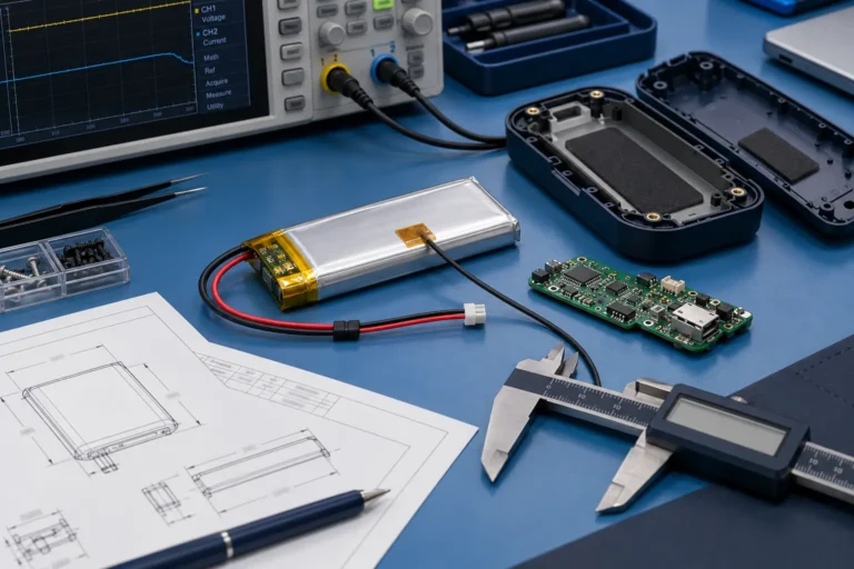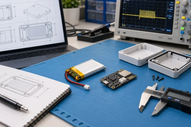
Custom Battery Pack Design Guide: Voltage, Capacity, Current, BMS and OEM Integration

Technically Reviewed By
Chief Scientist
Dr. Maximilian Weber is THOR Power’s Chief Scientist and a senior expert in lithium battery technology. His technical review focuses on battery safety, performance optimization, energy density and custom battery solution development.
Last technical review: September 2026

Written By
President of OEM Division & Custom Battery Specialist
Victor Xiong holds a Master’s degree from The Chinese University of Hong Kong, Shenzhen. He leads THOR Power’s OEM Division and focuses on custom battery solutions for global device brands, product developers and industrial customers.
A custom battery pack is not simply a group of cells wrapped in heat-shrink and connected to a protection board. It is an energy system that must work with the device load, charger, electronics, enclosure, operating environment, certification route and mass-production process. A pack can meet the requested voltage and capacity and still fail because the cell cannot support peak current, the connector overheats, the BMS threshold conflicts with normal operation, or the approved sample does not represent the production bill of materials.
For OEM and ODM projects, the most expensive battery problems usually begin before the first sample is built. A customer may provide only “12 V, 5 Ah” while the real product has a 25 A motor-start pulse, operates while charging, sits beside a heat source, must fit into a sealed enclosure and needs a specific transport or market certification. If those conditions are discovered after tooling, firmware or charger approval, the battery project becomes a redesign project.
A professional custom battery pack design process therefore begins with application requirements and risk, not a catalog cell. The engineer converts the product demand into a controlled battery specification across THOR Power’s custom battery product range: chemistry and cell model, series-parallel architecture, nominal and maximum voltage, usable energy, continuous and peak current, BMS logic, charging profile, connector and wire path, mechanical support, thermal management, documentation and production controls.
This guide explains that process in engineering depth. It includes calculation examples, representative OEM case scenarios, supplier evidence checklists and the questions that should be resolved before a battery sample becomes the mass-production reference. Product teams can use THOR Power’s custom battery solutions engineering review to define unknown requirements before the enclosure, charger and certification route are frozen.
Quick Answer for OEM Buyers
A custom battery pack should be designed by defining the device voltage window, real load profile, runtime target, cell chemistry, series-parallel configuration, BMS logic, charger, connector, wire path, thermal design, mechanical structure, validation plan and production change control. A safe and manufacturable pack is the one that stays within validated limits in the real product and remains consistent from approved sample to mass production.
Case Transparency Note
The engineering cases in this article are representative composite scenarios built from recurring battery-project patterns. They explain design decisions without identifying a customer or presenting confidential project data as a published THOR Power case study.
1. What Is Custom Battery Pack Design?
Direct answer: Custom battery pack design converts a device requirement into a controlled cell, voltage, capacity, BMS, charging, mechanical, thermal and production specification. The goal is not only to make a sample fit, but to make the battery work safely and repeatably in mass production.
Custom battery pack design is the process of translating a product requirement into a controlled electrochemical, electrical, thermal, mechanical and manufacturing architecture. The output is not just a drawing or a sample. It is a complete specification that defines what the pack is, how it should behave, how it will be tested and which items cannot change without approval.
The design begins at the device boundary. The battery must accept energy from the charger, deliver energy to the load, communicate with the product where required, survive the expected environment and fail in a controlled manner under foreseeable abnormal conditions. This system boundary is why battery selection cannot be separated from charger, firmware and enclosure decisions.
| Design Layer | What Must Be Defined | Why It Matters |
|---|---|---|
| Application and risk | Device function, user exposure, failure consequence, duty cycle and environment | Defines how conservative the architecture, validation and documentation must be. |
| Cell chemistry and model | Voltage window, capacity, current rating, temperature range, cycle life and supply route | The cell approval sheet establishes the operating limits; the format or chemistry name alone is insufficient. |
| Series-parallel topology | Series count, parallel count, group layout and current-sharing path | Sets pack voltage, capacity, available current, balancing need and fault energy. |
| Protection architecture | PCM/BMS, fuses, contactors, pre-charge, balancing, NTCs and firmware | Must distinguish normal control from independent protection and safe fault recovery. |
| Charging and power path | Charge voltage, current, termination, adapter, USB/dock behavior and operation while charging | A correct cell and BMS can still be damaged by an incompatible charger or reverse energy path. |
| Current path | Tabs, welds, busbars, wires, connectors, MOSFETs and shunts | Voltage drop and I²R heating occur through the complete path, not only inside the cells. |
| Mechanical and thermal design | Cell support, tolerance, expansion, insulation, vent path, heat sources and cooling | Controls damage, hot spots, swelling, vibration and propagation consequences. |
| Compliance and production | Standards, transport documents, BOM lock, traceability and change approval | Ensures that the tested sample and mass-production pack remain the same controlled model. |
2. Start With the Device, Not With a Battery Catalog
Direct answer: Start with the device because voltage, current, runtime, charger behavior, enclosure space, temperature and failure consequence decide the battery architecture. A catalog cell can look suitable while still failing under real load, heat or certification conditions.
Many project teams begin by choosing a cell that appears to fit the available space and then design the product around it. This can work for a simple low-load device, but it is risky when current pulses, charging behavior, heat or certification are not yet known. The better sequence is to define the device demand first and use it to screen battery directions.
The first requirement review should answer four questions: What must the battery deliver? What conditions will it experience? What happens if it shuts down or fails? Which product decisions are already locked? The last question is important because a locked enclosure or charger may remove otherwise suitable battery options.
| Requirement Area | Information to Capture | Common Hidden Risk |
|---|---|---|
| Electrical load | Standby, average, continuous, peak, pulse duration, duty cycle, inrush, stall and regenerative current | Averages hide short high-current events that drive cell, BMS, conductor and connector design. |
| Energy and runtime | Target runtime, recharge interval, usable capacity window and end-of-life requirement | Nameplate capacity is not equal to usable device energy. |
| Charging | Input source, charge current, operating while charging, recharge threshold, cold-charge policy and adapter faults | The charger and BMS must be coordinated with the exact cell and device power path. |
| Mechanical space | 3D space, tolerances, wire exit, connector, bend radius, fasteners, foam, BMS, label and assembly method | Battery space is more than length × width × height. |
| Thermal environment | Ambient range, nearby motors/processors, enclosure material, airflow and simultaneous charge/load | The hottest cell or connection may not be visible at the enclosure surface. |
| Product life | Expected cycles, calendar life, storage state of charge, field service and replacement method | A pack should remain safe after aging, not only when new. |
| Market and compliance | Destination markets, transport route, end-product category and customer approval requirements | Certification scope can influence cell, BMS, enclosure and traceability decisions. |
3. The Ten-Step Custom Battery Pack Engineering Workflow
Direct answer: A reliable custom pack workflow moves from use case and measured load to chemistry, voltage, runtime, current path, BMS, charger, enclosure, validation and production control. Each step should trace back to a device requirement or test result.
The following workflow is a practical sequence for reducing redesign risk. Some steps overlap, but each decision should be traceable to an application requirement or test result.
Step 1: Define the Use Case and Failure Consequence
The same electrical specification can require different safety margins in different products. A brief shutdown in a consumer electronic device is inconvenient; a shutdown in a power tool, monitoring, medical-support or backup-power system may have a higher consequence. The review should consider user access, location, supervision, replacement method and whether a battery fault can damage surrounding equipment.
This risk context determines whether the project needs redundant temperature sensing, a fuse in addition to the BMS, stronger mechanical containment, pack-level abnormal-condition testing, field event logging or stricter controlled-component rules.
Step 2: Measure the Real Load Profile
Battery current should be measured at the battery terminals under representative device operation. A product specification that lists only rated power or average current is usually incomplete. Motors, heaters, radios, pumps, processors and capacitive inputs can create brief loads that dominate voltage sag and protection behavior.
Record standby current, average current, continuous worst-case current, peak amplitude, pulse duration, pulse repetition, startup, stall or jam current, regenerative current and shutdown voltage. Repeat the measurement at low battery voltage and at the highest expected ambient temperature because converter and motor current can increase as pack voltage falls.
Representative Engineering Case 1: The 18 V Actuator That Worked on the Bench
Project situation: A compact actuator was described as an 18 V product with 6 A average current. The first pack used high-capacity cylindrical cells in a 5S2P configuration and a nominal 30 A BMS.
Hidden risk: The actuator required approximately 34 A for several seconds during cold startup and could approach stall current when the mechanism was obstructed. The cells, weld path and connector experienced excessive voltage drop, while the BMS either tripped or ran near its thermal limit.
Engineering response: The pack direction was re-evaluated using high-power cells, greater parallel current capability, a lower-resistance conductor path, temperature sensing near the current path and device firmware that detected prolonged stall. The BMS rating was validated by temperature rise and fault response rather than accepted from its marketing label.
Buyer lesson: Average current and a printed BMS ampere rating are not enough. The pulse shape, cold-start behavior, stalled-load duration and complete current path must be measured.
Step 3: Select Chemistry, Cell Format and Exact Cell Model
Chemistry influences nominal voltage, energy density, thermal behavior, cycle life and charge profile. Cell format influences pack geometry, mechanical support, heat transfer, venting and assembly method. The engineer should screen pouch, cylindrical, prismatic and LiFePO4 directions against the real product rather than treating one format as universally superior.
The exact cell model is the controlled item. Two cells with the same size and advertised capacity can have different continuous-current ratings, charge limits, impedance, temperature ranges and internal construction. Cell substitution after validation requires engineering review and may require repeated testing or documentation updates.
| Battery Direction | Typical Fit | Engineering Advantage | Design Priority |
|---|---|---|---|
| Custom LiPo pouch | Thin or irregular compact devices; low-to-moderate current or model-specific high-rate applications | Dimensional flexibility and packaging efficiency | Swelling allowance, tab and edge protection, uniform support, charge control and puncture protection |
| 18650 / 21700 cylindrical | Tools, robotics, lighting, portable equipment and modular packs | Rigid can, broad model range and scalable series-parallel design | Authentic sourcing, model matching, wraps, terminal insulation, welding, vent clearance and propagation |
| Prismatic lithium-ion | Larger industrial or modular systems | Fewer cells and efficient module packaging | Compression, busbar design, terminal protection, expansion and higher energy per cell |
| LiFePO4 / LFP | Backup power, energy storage and selected industrial or portable systems | Cycle life and comparatively high thermal stability | Correct lower-voltage BMS/charger, balancing, compression, low-temperature charging and system protection |
For product-specific directions, compare Custom LiPo Batteries, Lithium-ion Battery Packs, 18650 / 21700 Battery Packs and Custom Special Battery Packs. For model-level screening, use LiPo battery model options for pouch-cell dimensions and capacity ranges, 18650 / 21700 cell model options for cylindrical-cell capacity and current comparison, and energy storage battery model options for LFP or backup-power architecture screening before locking the pack direction.
For early pouch-cell screening, capacity class (small, medium, high or large) can help narrow the first discussion, but final selection must still confirm the exact cell model against current, charger, structure and end-of-life runtime.
Step 4: Define Voltage From the Full Operating Window
Nominal voltage is a convenient label, not the complete interface. The product must tolerate the pack at maximum charge voltage, expected nominal voltage, discharge cutoff and transient conditions. Series count increases voltage: each series group adds the cell voltage, while the ampere-hour capacity remains approximately that of one parallel group.
Voltage Calculations
Pack nominal voltage ≈ cell nominal voltage × number of series groups
Pack maximum voltage = cell maximum charge voltage × number of series groups
Pack minimum operating voltage must consider cell cutoff, BMS cutoff and device undervoltage behavior
The battery, device input range and charger must agree at all points. A 24 V request is incomplete until the product team provides the actual permitted minimum and maximum input voltage. This is especially important when comparing lithium-ion and LiFePO4 configurations, because packs with similar nominal labels can have different charge endpoints.
Representative Engineering Case 2: The “24 V” Specification That Exceeded the Device Input
Project situation: An industrial controller requested a rechargeable 24 V pack. The electronic input stage was later found to have a 26 V absolute operating limit.
Hidden risk: A common 7S lithium-ion pack can reach 29.4 V at full charge, while an 8S LiFePO4 direction can also approach approximately 29.2 V depending on the cell and charger. Both exceed the device limit despite appearing to match a “24 V” requirement.
Engineering response: The battery and electronics teams reviewed the real operating window. Options included redesigning the input stage, using a regulated output architecture or selecting a different battery topology with verified runtime and current capability. The charger was defined only after the final topology was approved.
Buyer lesson: Never select series count from the nominal voltage name alone. The correct input is the device minimum, normal and absolute maximum voltage range.
Step 5: Calculate Energy, Capacity and Real Runtime
Ampere-hours describe charge capacity, while watt-hours describe nominal stored energy. Runtime depends on energy delivered through the complete system, including converter efficiency, voltage cutoff, usable state-of-charge window, temperature, load variation and aging. A customer asking for “5000 mAh” without voltage has not defined an energy requirement.
Energy and Runtime Formulas
Nominal energy (Wh) = nominal voltage (V) × capacity (Ah)
Estimated runtime (h) ≈ nominal energy × usable-energy factor × system efficiency ÷ average load (W)
Required nominal energy ≈ required load energy ÷ (usable-energy factor × system efficiency)
The usable-energy factor should include the design state-of-charge window, voltage cutoff, temperature and end-of-life margin. System efficiency should include DC/DC conversion and other power-path losses. Peak current must still be checked separately because an energy calculation does not prove power capability. For early estimation, use the battery capacity and runtime calculators, then confirm the final pack direction with measured load data, cell-model limits, charger behavior and end-of-life margin.
| Calculation Item | Result | Engineering Interpretation |
|---|---|---|
| Device average load | 12 W | Measured under representative operation |
| Runtime target | 8 h | Required load energy = 96 Wh |
| Assumed usable-energy factor | 85% | Allows for cutoff, operating window and margin |
| Assumed conversion efficiency | 90% | Must be validated in the final device |
| Minimum nominal pack energy | ≈125.5 Wh | 96 Wh ÷ (0.85 × 0.90) |
| At a 14.8 V nominal architecture | ≈8.48 Ah minimum | 125.5 Wh ÷ 14.8 V; practical design requires cell/configuration and aging review |
Representative Engineering Case 3: The Runtime Target That Needed 25% More Nominal Energy
Project situation: A monitoring gateway required eight hours of operation at approximately 12 W. The buyer initially requested a 96 Wh battery because 12 W × 8 h = 96 Wh.
Hidden risk: The calculation ignored converter losses, voltage cutoff, cold-temperature behavior, capacity tolerance and the requirement to meet runtime after aging. A 96 Wh nameplate pack would not reliably deliver 96 Wh to the device.
Engineering response: The project converted the load requirement into nominal battery energy using an agreed usable-energy factor and efficiency. The final capacity was selected after verifying cell current, physical volume, thermal behavior and end-of-life runtime.
Buyer lesson: Runtime should be calculated from usable system energy, not from nameplate watt-hours alone. State all assumptions so the supplier and buyer are evaluating the same target.
Step 6: Validate Continuous Current, Peak Current and the Complete Current Path
Current capability is not determined by the cells alone. Every element contributes resistance: cell impedance, welds, tabs, busbars, wires, connectors, shunt, MOSFETs, contactors and PCB copper. The same current flows through each series element, and local resistance can produce a hot spot even when the cells remain within their rating.
Voltage Drop and Heat
Voltage drop across a path: Vdrop = I × R
Heat generated in a resistive path: P = I² × R
Example: 20 A through 20 mΩ produces 0.4 V drop and 8 W of heat
This squared-current relationship is why a small resistance that looks harmless at 5 A can become important at 20 A. Current-path validation should include continuous operation, repeated pulses, stalled load, connector mating condition, aged components and the highest expected ambient temperature.
Wire gauge must not be selected by current alone. Length, bundle, insulation temperature rating, duty cycle, allowable voltage drop, ambient temperature, enclosure, termination quality and regulatory requirements all affect the result. Connector selection must also consider contact resistance, pin count, locking, polarity, mating cycles, hot-plug behavior and whether a similar connector could be connected incorrectly. Connector model, wire length, polarity, NTC and protection requirements should be finalized through Connector, Wire & PCM/BMS Customization before the sample drawing is approved.
Step 7: Engineer the PCM/BMS, Fuse, Balancing and Communication
A BMS is not adequately specified by series count and a single current number. The design must match chemistry, cell-model voltage limits, charge and discharge ports, current waveform, short-circuit energy, temperature range, sensor locations, balancing strategy, recovery behavior and device communication.
For small packs, the protection circuit may use MOSFETs to disconnect the current path. Higher-energy systems may require a fuse, contactor, pre-charge circuit or redundant protection according to the risk assessment. Normal charger control should not rely on repeatedly reaching the BMS overvoltage cutoff, and normal device shutdown should occur before deep-discharge protection trips.
| BMS Design Area | What to Define | Customer Pain Point |
|---|---|---|
| Cell/group monitoring | Number of series groups, chemistry-specific thresholds, measurement accuracy and wiring | Total pack voltage can hide one group outside its safe range. |
| Current protection | Continuous, peak and short-circuit thresholds; delay; MOSFET/contactor capability | A printed “30 A” rating does not define pulse behavior, temperature rise or interruption safety. |
| Temperature | NTC value, quantity, placement, charge/discharge limits and recovery | One sensor on the BMS may miss the hottest cell, connector or MOSFET. |
| Balancing | Passive or active method, start condition, current and thermal effect | Balancing reduces drift; it cannot repair a damaged or badly mismatched cell group. |
| Fuse / current interruption | Pack fuse, cell/group links, contactor and pre-charge where required | Electronic switches can fail; independent interruption may be needed according to risk. |
| Communication | SMBus, I²C, UART, CAN or custom protocol; state and fault messages | Protocol, wake/sleep, firmware update and fault recovery must be tested with the device. |
| Low-power behavior | Sleep current, storage mode, ship mode and wake-up method | BMS consumption can deeply discharge a stored pack if logistics and service periods are long. |
Multi-series battery monitors can combine individual cell-voltage measurement, current and temperature monitoring, balancing and protection, but the hardware platform still has to be adapted and validated for the actual cells, current path and end product. The weakest cell can limit a series stack, and balancing addresses mismatch rather than replacing cell quality or pack design. Active balancing can improve usable stack energy in selected systems, but it introduces conversion, thermal and control trade-offs that must be evaluated at pack level. For the broader failure-mechanism and risk-control discussion, use the lithium-ion battery safety guide as the system-level safety reference and keep this article focused on project design workflow.
Step 8: Match the Charger, Power Path and Device Firmware
The charger defines normal energy input. The BMS provides protection when normal control or the external circuit becomes abnormal. Mixing these functions creates poor designs, such as charging every cycle until BMS overvoltage shutdown or selecting a generic adapter because the connector fits.
The review should define maximum charge voltage, constant-current level, constant-voltage termination, recharge behavior, safety timer, temperature policy, low-voltage recovery, adapter tolerance, reverse-polarity protection and whether the device operates while charging. USB, docking and solar inputs may require additional power-path and source-management logic.
Motor or actuator products can return energy during braking. Backup-power products may switch rapidly between adapter and battery. If current can flow back into the pack outside the approved charging path, the battery, BMS and firmware must handle that condition intentionally.
Step 9: Design the Mechanical Structure and Thermal Path
Battery space is not only the cell volume. The pack needs tolerances, holders or compression, BMS, insulation, wires, connector body, bend radius, strain relief, foam, label, enclosure interface and assembly access. Pouch cells also need allowance for normal dimensional change; cylindrical cells need protected wraps, terminal insulation and vent clearance; prismatic cells need manufacturer-appropriate compression and terminal structure.
The mechanical design should prevent concentrated pressure, abrasion, puncture, tab bending, wire crushing and contact with sharp fasteners. It should survive drop, vibration, transport and installation loads without creating a latent internal or electrical fault. Serviceable packs must prevent users from installing an incompatible voltage, chemistry or connector orientation.
Thermal design begins with heat sources and paths. Cell heat, connector heat, MOSFET heat, charger heat and nearby device electronics can combine. The hottest point may occur during low state of charge, motor stall, simultaneous charging and operation, high ambient temperature or after the cells have aged. Sensor locations should follow measured hot spots rather than convenient PCB positions.
| Thermal Input | What to Evaluate | Common Failure in Development |
|---|---|---|
| Ambient and enclosure | Maximum/minimum temperature, sealed or ventilated housing, solar or nearby heat | Room-temperature bench testing can miss the production hot spot. |
| Duty cycle | Continuous load, repeated pulse, charge while operating and stall conditions | A short test may not reach thermal equilibrium. |
| Aging allowance | Higher cell and connection resistance over life | A new pack may pass while an aged pack exceeds the temperature limit. |
| Sensor map | Cells, connector, BMS/MOSFET, charger or center of dense pack | A single external sensor can respond too late. |
| Heat path | Air, enclosure conduction, thermal pads, spacers and barriers | Cooling one region can unintentionally heat or block venting in another. |
| Abnormal condition | Blocked airflow, failed fan, jammed motor, wrong adapter or cell fault | The design must control consequence, not only normal performance. |
Representative Engineering Case 4: The Pouch Battery That Fit the CAD but Not the Real Product
Project situation: A compact device enclosure was completed around the nominal dimensions of a 1S pouch battery. The prototype fit tightly and delivered the required runtime.
Hidden risk: The design did not include cell tolerance, normal dimensional change, edge protection, BMS and wire stack-up, connector bend radius or assembly pressure. The enclosure ribs placed concentrated force near the pouch edge.
Engineering response: The product team revised the battery cavity and support method, protected the pouch edges and tabs, defined the wire exit and allowed model-specific dimensional tolerance. Mechanical validation used production-intent parts, not a hand-assembled early sample.
Buyer lesson: A battery that fits a CAD box may still be mechanically unsafe or impossible to assemble consistently. The battery drawing and enclosure design must be reviewed together.
Step 10: Validate the Sample, Lock the BOM and Control Mass Production
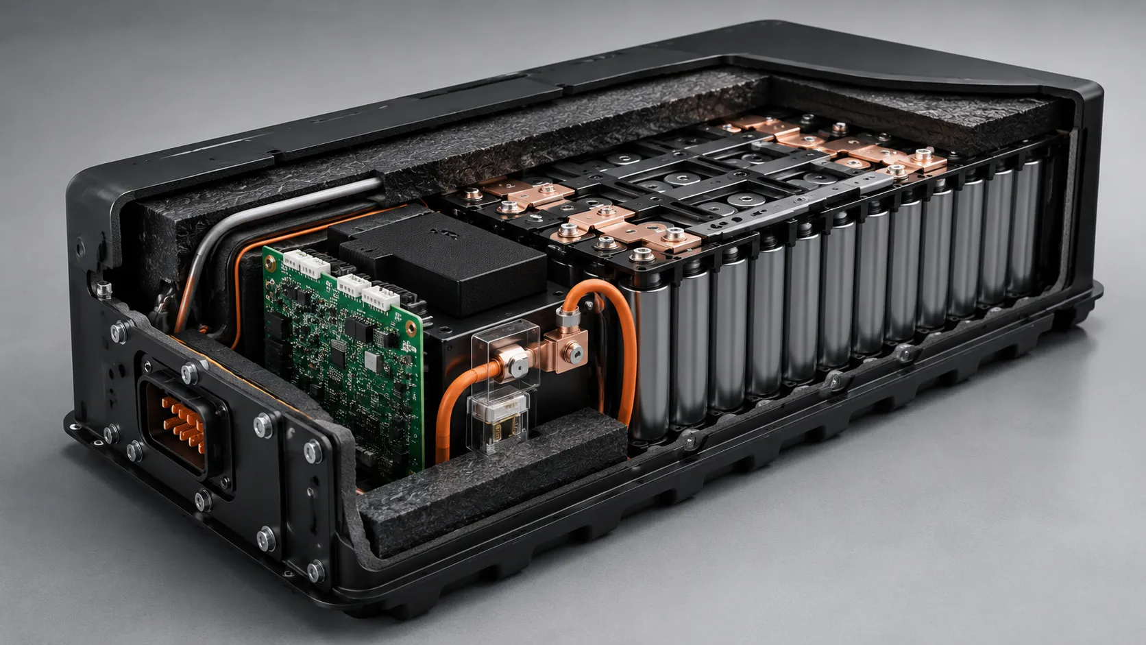
A working sample is evidence that one assembly worked under the conditions tested. It is not evidence that the design is ready for production. The validation plan should compare the sample with the final cell, BMS, charger, wires, connector, conductors, insulation, enclosure, firmware and manufacturing processes.
Testing should be divided into requirements: electrical performance, thermal performance, protection functions, charger and device integration, mechanical durability, environmental exposure, aging and compliance. Test limits and acceptance criteria should be agreed before the test so that a result is not reinterpreted after failure. Pilot approval should also verify that the documented battery pack production process can reproduce the approved cell screening, joining parameters, insulation, traceability, aging and final-test controls.
| Validation Area | What to Test | Approval Reminder |
|---|---|---|
| Electrical | Voltage window, capacity, runtime, efficiency, standby, continuous and peak current | Use the final device and representative firmware; record voltage sag and shutdown behavior. |
| Protection | Overcharge, over-discharge, over-current, short circuit, temperature and recovery | Confirm thresholds, delays, sensor faults and safe restart behavior. |
| Thermal | Worst-case load, charge, simultaneous operation, high ambient and aged resistance allowance | Measure cells, current path, BMS, connector and enclosure hot spots. |
| Mechanical | Fit, assembly, tolerance, drop, vibration, compression, strain relief and service | Use production-intent enclosure, hardware and wire routing. |
| Charging / device integration | Correct charger, wrong adapter scenarios, USB/dock, operation while charging and regenerative flow | Do not validate the battery only as a stand-alone pack. |
| Life and storage | Cycle profile, calendar storage, self-discharge, low-voltage storage and logistics duration | Include BMS sleep current and end-of-life performance criteria. |
| Compliance | Transport and market-specific tests for the final controlled model | Reports must identify the exact cell, configuration and report holder. |
| Pilot production | Process capability, joining, insulation, polarity, traceability, aging and final test | A hand-built sample does not prove production repeatability. |
Representative Engineering Case 5: The Approved Sample That Changed Before Mass Production
Project situation: A customer approved a battery sample and completed device testing. Before mass production, a similar cell, a different MOSFET and a shorter wire were proposed to improve availability and assembly speed.
Hidden risk: The pack looked identical, but the cell current capability, BMS temperature rise, voltage drop and documentation scope could change. The existing validation no longer represented the production BOM.
Engineering response: The safety-critical bill of materials and process parameters were locked. Proposed substitutions entered a formal change review that identified which electrical, thermal, mechanical and compliance tests had to be repeated before approval.
Buyer lesson: Sample approval is not complete until controlled components, drawings, firmware and key manufacturing processes are frozen and traceable.
Ready to Turn the Requirements Into a Pack Specification?
Send the voltage window, load waveform, runtime target, battery space, charger and connector requirements. THOR Power can review the cell configuration, current path, PCM/BMS, mechanical structure and validation plan before samples are built.
4. How to Define Validation Acceptance Criteria
Direct answer: Validation criteria should define what must be measured, under which load and temperature, and what result is acceptable. Runtime, voltage sag, peak current, BMS recovery, temperature rise, charger behavior and production repeatability need written pass/fail limits.
A validation plan should not only list tests. It should define what will be measured, which sample configuration represents production, and what evidence is required before the battery becomes the approved reference. Acceptance criteria should be agreed before testing so that a weak result is not reinterpreted after failure.
| Validation Area | What to Measure | Acceptance Criteria Should Define |
|---|---|---|
| Voltage behavior | Maximum charge voltage, cutoff voltage, voltage sag and device shutdown behavior | Allowed voltage window, minimum operating voltage, recovery behavior and whether the device shuts down before protection trips. |
| Runtime and capacity | Usable energy under representative load, temperature and end-of-life assumptions | Beginning-of-life and end-of-life runtime targets, usable-energy factor and efficiency assumptions. |
| Current path | Continuous current, peak current, pulse duration, voltage drop and temperature rise | Maximum allowed temperature rise for cells, conductors, BMS/MOSFETs, wires and connector under real duty cycle. |
| Protection behavior | Overcharge, over-discharge, over-current, short circuit, temperature and recovery | Thresholds, delays, recovery rules, sensor-fault response and whether automatic restart is allowed. |
| Charging and power path | Normal charger curve, wrong adapter scenarios, operation while charging and backflow | Approved charger behavior, low-temperature policy, termination logic and safe handling of abnormal inputs. |
| Mechanical and thermal | Fit, tolerance, compression, swelling allowance, drop, vibration, hot spots and enclosure effects | Production-intent enclosure, allowed pressure points, sensor locations, vent path and hot-spot limits. |
| Production consistency | Cell lot, BMS revision, weld program, connector, wire, insulation and final test records | Which parts and processes are controlled, what can change only by approval and what revalidation is required. |
5. How Series and Parallel Configuration Changes the Pack
Direct answer: Series count changes voltage window, BMS monitoring channels and charger requirements. Parallel count changes nominal capacity, current capability, fault current, thermal density and pack size. The S/P configuration must be validated as part of the complete device.
Series and parallel connections solve different requirements. Series groups raise voltage. Parallel cells increase ampere-hour capacity and current capability, but also change current sharing and available fault current. The chosen topology determines BMS architecture, cell matching, conductor design, heat distribution and documentation.
| Design Choice | What It Changes | Engineering Consequence |
|---|---|---|
| More cells in series | Higher nominal and maximum voltage | More group-monitoring channels, balancing, insulation and charger voltage; one weak group can limit the pack. |
| More cells in parallel | Higher Ah, Wh and current capability at the same series voltage | Current sharing depends on cell and connection resistance; fault current and stored energy increase. |
| Larger single cells | Fewer interconnections and sensing points | Greater energy per cell and different mechanical/compression requirements. |
| Many small cells | Flexible shape and scalable power/energy | More welds, insulation points, vent paths and propagation interactions. |
| Common-port BMS | Charge and discharge share the same current path | Simpler wiring but fault and charger behavior must fit the application. |
| Separate-port BMS | Dedicated charge and discharge paths | Can support different limits but adds wiring and integration complexity. |
6. From Sample Approval to Design Freeze
Direct answer: Sample approval should freeze the controlled items that affect performance and safety: cell model, S/P topology, BMS, fuse, connector, wire, weld program, enclosure interface and final test method. Later substitutions should trigger engineering review.
Not every cosmetic item has the same engineering importance, but certain changes can alter safety, performance or report coverage. These items should be identified as controlled characteristics in drawings, the approved BOM or a customer-specific specification.
- Cell manufacturer, exact model, chemistry, production-lot rules and approved sourcing channel.
- Series-parallel configuration, cell orientation, matching criteria and interconnection layout.
- PCM/BMS hardware, firmware, protection thresholds, balancing, MOSFETs, shunt, fuse and NTC values/locations.
- Nickel or copper conductors, busbars, weld or joining program, wire gauge/length and connector/polarity.
- Insulation, holders, foam, compression, enclosure interface, vent path and strain relief.
- Charger model or charge profile, adapter limits, communication protocol and device shutdown behavior.
- Label model, pack identification, transport packaging, final test items and traceability format.
The change-control rule should specify who can approve a deviation, what evidence is required and whether the change affects transport, safety or end-product certification. “Equivalent component” is not an engineering conclusion until equivalence has been demonstrated for the relevant function.
| Project Gate | What Should Be Frozen | Why It Matters |
|---|---|---|
| Requirement freeze | Voltage window, load profile, runtime target, charger, environment, certification route and approval criteria | Prevents the supplier from quoting and sampling against assumptions. |
| Architecture freeze | Chemistry direction, exact cell model, series-parallel topology, BMS concept, connector direction and mechanical envelope | Confirms that the chosen architecture can satisfy electrical, thermal and mechanical constraints. |
| Sample approval | Production-intent cell, BMS, wire, connector, conductors, insulation, enclosure interface and charger behavior | Makes the sample representative of the design that will move toward certification and pilot production. |
| Pilot run | Assembly method, weld/joining program, incoming checks, final tests, labeling, packaging and traceability | Checks whether the approved design can be built consistently, not only by hand. |
| Mass-production change control | Rules for cell, BMS, MOSFET, connector, wire, insulation, firmware and process substitutions | Protects validation results, certification scope and long-term supply stability. |
7. Plan Certification and Transport Requirements During Design
Direct answer: Certification and transport planning should begin before sample approval. Cell model, topology, BMS, enclosure, energy, wiring and charger choices can affect UN 38.3, IEC/UL evidence, shipping documents and the customer’s end-product approval path.
Compliance should not be treated as a document requested after the pack is finished. Standards can influence the approved cell, protective devices, enclosure, wiring, test samples and report holder. The applicable route depends on the battery format, product category, destination market and whether the battery is portable, industrial, stationary or integrated into another device.
IEC 62133-2:2017+A1:2021 specifies requirements and tests for portable sealed secondary lithium cells and batteries under intended use and reasonably foreseeable misuse. IEC 62619:2022 addresses secondary lithium cells and batteries used in industrial applications, including stationary applications. The UN Manual of Tests and Criteria, Sub-section 38.3, covers transport testing for lithium cells and batteries. UN 38.3 supports transport compliance; it is not a complete end-product safety certification.
| Reference | Primary Purpose | OEM Buyer Reminder |
|---|---|---|
| UN 38.3 | Transport testing for lithium cells and batteries | Confirm the tested model and configuration; a test summary does not replace end-product safety approval. |
| IEC 62133-2 | Portable sealed secondary lithium cells and batteries | Confirm the exact edition, model scope, report holder and national adoption. |
| IEC 62619 | Industrial secondary lithium cells and batteries, including stationary applications | Consider for industrial, backup, telecom, AGV and related applications where applicable. |
| UL 1642 / UL 2054 | Lithium cells / household and commercial battery packs | Cell, pack and end-product scopes are different; select by final application. |
| Application standards | Tools, medical, ICT, appliances, mobility, energy storage and other products | The battery is one subsystem; final-device or installation requirements may add tests and safeguards. |
Review battery certificates and compliance documents early, while confirming that every report matches the exact production model and destination market.
8. What an OEM Buyer Should Send Before Sample Development
Direct answer: An OEM should send the device voltage window, load waveform, runtime target, battery space, charger details, environment, target market, certification needs and volume forecast. Without these inputs, the supplier is guessing at the pack architecture.
A supplier can recommend a better pack when the first inquiry contains real engineering context. Sending only voltage, capacity and dimensions often produces a quotation based on assumptions, not a production-ready design.
| Workflow Step | Information to Send | Why It Matters |
|---|---|---|
| Use case and risk | Device function, target market, user access, shutdown consequence and operating environment. | Sets validation depth, protection strategy and documentation expectations. |
| Real load profile | Standby, average, continuous, peak, inrush, stall or regenerative current, including pulse duration and duty cycle. | Prevents cell, BMS, connector and wire selection from being based on averages only. |
| Chemistry and cell direction | Preferred chemistry or format if known, plus constraints on size, weight, cost, supply route or safety margin. | Lets the supplier compare LiPo, cylindrical, LFP or special-pack directions without guessing. |
| Voltage window | Nominal input, allowed minimum and maximum voltage, undervoltage behavior and charger voltage limits. | Avoids choosing series count from a misleading 12 V or 24 V label. |
| Runtime and energy | Runtime target at beginning and end of life, recharge interval, duty cycle and efficiency assumptions. | Turns nameplate Ah or Wh into usable system energy. |
| BMS and communication | Protection functions, NTC, wake/sleep, communication protocol, fault handling and replaceability needs. | Defines what the pack must do beyond delivering power. |
| Charging and power path | Adapter, USB, dock, solar or other input; operation while charging; low-temperature policy and backflow risks. | Prevents charger and firmware behavior from damaging an otherwise suitable pack. |
| Mechanical and thermal | 3D battery space, enclosure material, fasteners, wire exit, connector access, heat sources, airflow and service constraints. | Shows whether the pack can be assembled, cooled and protected in the real product. |
| Compliance and logistics | Destination markets, transport route, required reports, sample quantity, packaging and production forecast. | Aligns design decisions with certification, shipment and long-term supply. |
| Approval criteria | Tests required for sample approval, pilot build, final device validation and production change control. | Makes clear what evidence is needed before the sample becomes the reference design. |
9. What a Professional Battery Supplier Should Return
Direct answer: A professional supplier should return a reviewable engineering proposal, not only a price. It should explain chemistry, cell model, voltage, capacity, BMS, current path, connector, charger assumptions, validation plan, controlled items and production risks.
A professional response should include more than a price and an outline drawing. It should identify the proposed architecture, calculation basis, protection concept, mechanical assumptions, validation plan, controlled items and documentation scope. Unknown inputs—such as peak current, charger behavior, enclosure temperature or certification scope—should be recorded as open assumptions rather than hidden inside a low quotation.
| Supplier Output | Minimum Content | Why It Builds Trust |
|---|---|---|
| Recommended architecture | Chemistry, exact cell direction, series-parallel configuration and nominal/max/min voltage | Shows how the pack matches the device rather than merely repeating the inquiry. |
| Performance basis | Nominal energy, usable runtime assumptions, continuous/peak current and temperature range | Makes calculation assumptions visible and reviewable. |
| Protection concept | PCM/BMS functions, thresholds, balancing, sensors, fuse/contactors and communication | Allows the buyer to verify interaction with charger and firmware. |
| Mechanical proposal | Dimensions/tolerance, wire exit, connector, support, insulation, expansion and enclosure interface | Prevents the pack from becoming a late mechanical surprise. |
| Validation plan | Electrical, thermal, mechanical, device-integration, life and compliance tests | Defines what evidence will support sample approval. |
| Controlled-items list | Cell, BMS, wire, connector, conductors, insulation, firmware and key process parameters | Closes the gap between approved sample and mass production. |
| Documentation scope | Available cell/pack reports, UN 38.3, SDS/MSDS and planned certifications | Clarifies what exists and what still requires testing or customer confirmation. |
10. How to Evaluate the Supplier Behind the Proposal
Direct answer: Evaluate a battery supplier by the quality of its engineering questions, test plan, change-control discipline and evidence, not only by sample speed or quoted capacity. Good suppliers explain limits, assumptions and risks before production.
After reviewing the proposal, evaluate whether the supplier can connect each recommendation to evidence and maintain the approved design in production. Focus on five areas: requirement review, exact cell and architecture definition, protection and integration, validation evidence, and production change control.
| Evaluation Area | What to Look For |
|---|---|
| Requirement review | The supplier asks for load profile, charger, temperature, enclosure, certification and failure-consequence data before recommending a pack. |
| Exact cell and architecture | The proposal identifies cell model, sourcing route, series-parallel configuration, voltage window and known assumptions. |
| Protection and integration | BMS thresholds, sensor locations, fuse strategy, connector, wire path and charger behavior are explained as one system. |
| Validation evidence | The supplier can define runtime, voltage sag, temperature rise, protection, mechanical and final-device tests with acceptance criteria. |
| Production control | Cell lots, BMS revision, weld program, connector, wire, firmware, final tests and change-control rules are traceable after sample approval. |
11. How THOR Power Supports Custom Battery Pack Design
THOR Power supports custom LiPo pouch batteries, lithium-ion battery packs, 18650 / 21700 packs, LiFePO4 backup and energy-storage batteries and custom special battery packs. The engineering review begins with the product requirements, not a preselected catalog model.

The project workflow covers application review, load-profile confirmation, chemistry and cell selection, voltage and series-parallel design, capacity and runtime estimation, PCM/BMS and fuse matching, connector and wire confirmation, mechanical and thermal review, sample development, final-device testing, documentation planning and mass-production control.
Before recommending a direction, the team reviews battery type, voltage range, capacity, continuous and peak current, pulse duration, charger, temperature range, available space, connector, wire, PCM/BMS, pack structure, insulation, operating environment, certification needs and production feasibility. Unknown items are recorded as assumptions to be verified, rather than hidden inside a quotation.
Production controls can include cell appearance and batch review, open-circuit-voltage and internal-resistance checks, capacity verification according to project requirements, cell matching, weld or joining inspection, insulation and polarity checks, PCM/BMS functional testing, charge-discharge validation, aging and final electrical inspection. The custom battery project process is designed to move from requirements to a controlled sample and then to stable long-term supply, with safety-critical parts and process changes reviewed before implementation.
12. When to Involve THOR Power
The best time to involve a battery engineer is before the enclosure, charger, connector, firmware limits and certification route are locked. Early review provides more options to balance runtime, current, dimensions, temperature, documentation, cost and supply stability.
If the project already has a prototype, provide the current battery direction, device load data, charger, enclosure drawing, target market and observed problems. The review can determine whether the issue is cell selection, topology, BMS logic, current path, thermal design, mechanical fit or a combination of several layers.
13. Key Takeaways for OEM and ODM Buyers
- Custom battery pack design begins with the device load, voltage window, charger, environment and failure consequence, not with a catalog cell.
- Nominal voltage must be checked against maximum charge voltage, minimum operating voltage and the device input limits.
- Runtime is based on usable system energy and efficiency, not only nameplate ampere-hours or watt-hours.
- Peak current, pulse duration, stall and regenerative behavior can dominate the cell, BMS, connector and conductor design.
- A BMS current label is not a complete specification. Thresholds, delay, temperature, balancing, fuse strategy, recovery and communication matter.
- Voltage drop and heat occur through the complete current path. Small resistance becomes important because heat rises with the square of current.
- Battery space must include tolerances, support, insulation, BMS, wires, connector, bend radius, label and cell expansion or compression needs.
- A successful prototype is not production approval until the final BOM, firmware, drawings and key processes are locked and validated.
- Certification and transport planning should begin during design because report scope depends on the exact model and final application.
- Representative cases show that many failures originate from incomplete requirements rather than a lack of available battery cells.
14. Conclusion
A custom battery pack is successful when it delivers the required energy and power inside a controlled electrical, thermal and mechanical envelope throughout the expected life of the product. Reaching the requested voltage and capacity is only the beginning. The design must also survive peak load, charge correctly, manage imbalance and temperature, fit without damaging cells, communicate with the device where required and remain consistent from prototype to mass production.
The most effective way to reduce cost and schedule risk is to expose unknowns early. Product teams should define the real voltage range, current waveform, runtime assumptions, charger, battery space, environment, certification route and approval criteria before tooling is frozen. Battery suppliers should respond with transparent assumptions, a controlled architecture and evidence that connects the sample to the production pack.
THOR Power supports this process across custom LiPo, lithium-ion, 18650 / 21700, LiFePO4 and special battery-pack projects. The objective is not to force every application into one standard pack, but to select and validate the battery architecture that best fits the device, customer risk and long-term supply requirements.
Planning a Custom Battery Pack?
Send the voltage window, load waveform, runtime target, battery space, charger, connector and compliance requirements. THOR Power can review the cell configuration, current path, PCM/BMS and validation plan before samples are built.
15. FAQ: Custom Battery Pack Design
What information is needed to design a custom battery pack?
At minimum, provide the device voltage range, continuous and peak current, pulse duration, runtime target, charging method, available space, connector, wire length, temperature range, target market and expected quantity. Device drawings and measured load data significantly improve the first recommendation.
How do I calculate battery pack voltage?
Choose the number of cells or groups in series according to the exact cell nominal, maximum-charge and minimum-discharge voltages. Verify that the device and charger support the entire pack voltage window. Do not choose series count from a nominal “12 V” or “24 V” label alone.
How do I calculate battery capacity and runtime?
Convert capacity to nominal energy using watt-hours, then account for the usable state-of-charge window, converter efficiency, temperature, load variation and aging. Runtime should be validated in the final device because average load alone may not represent peak or standby behavior.
How do I choose a BMS for a custom battery pack?
Match the BMS to chemistry, series count, cell voltage limits, continuous and peak current, short-circuit behavior, sensor locations, balancing, fuse or contactor strategy, communication, sleep current and fault-recovery policy. A printed ampere rating alone is insufficient.
Does a BMS replace the charger?
No. The charger should control normal charge voltage, current and termination. The BMS is an independent protection and monitoring layer. Repeatedly relying on BMS overvoltage shutdown as normal charge termination is poor system design.
How should wire gauge and connector size be selected?
Evaluate continuous and peak current, length, voltage drop, I²R heating, duty cycle, ambient temperature, bundle conditions, insulation rating, contact resistance, locking and mating cycles. Validate the final wire and connector through temperature-rise and device testing.
Why can a battery fit the drawing but fail mechanical review?
The available space may omit cell tolerance, swelling or compression, holders, insulation, BMS, wire bend radius, connector body, strain relief, label and assembly access. Enclosure ribs or fasteners can also create concentrated pressure or abrasion.
When should battery certification be planned?
Plan it during architecture selection, before the cell, BMS, enclosure and charger are frozen. Applicable requirements depend on whether the product is portable, industrial, stationary or part of another regulated device, and transport testing does not replace end-product approval.
Can a different cell or BMS be substituted after sample approval?
Only after engineering change review. A visually similar cell or BMS component can change current capability, temperature rise, protection behavior, cycle life and certification scope. Identify the tests and documents affected before approving the change.
How should an OEM evaluate a custom battery manufacturer?
Evaluate the supplier’s requirement review, exact cell sourcing, BMS and charger engineering, current-path and thermal validation, mechanical design, sample testing, traceability, documentation support and change control. Do not evaluate only price, capacity and a generic certificate.
16. References
- NASA. Guidelines on Lithium-Ion Battery Use in Space Applications.
- NREL. Integration Issues of Cells into Battery Packs.
- NREL. Battery Pack Thermal Design.
- Texas Instruments. TIDA-00449 10s Battery Pack Monitoring, Balancing and Protection Reference Design.
- Texas Instruments. Cell Balancing With BQ769x2 Battery Monitors.
- Analog Devices. Battery Stack Monitor Maximizes Performance of Li-Ion Batteries.
- International Electrotechnical Commission. IEC 62133-2:2017+A1:2021.
- International Electrotechnical Commission. IEC 62619:2022.
- UNECE. UN Manual of Tests and Criteria, Revision 8 (Sub-section 38.3).
- NASA. New Li-Ion Technology Trends and Validation Process.
- UL Solutions. Battery Safety Testing and Certification.
- NREL. Thermal Safety Management in Li-Ion Batteries.
- Analog Devices. Active Battery Cell Balancing.
- Texas Instruments. Battery Management ICs Overview.
The engineering cases in this article are representative composite scenarios built from recurring battery-project patterns. They are intended to explain design decisions without identifying a customer or presenting confidential project data as a published THOR Power case study.