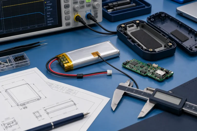
LiPo Batteries for Wearable and Portable Medical Devices: OEM Design and Validation Guide
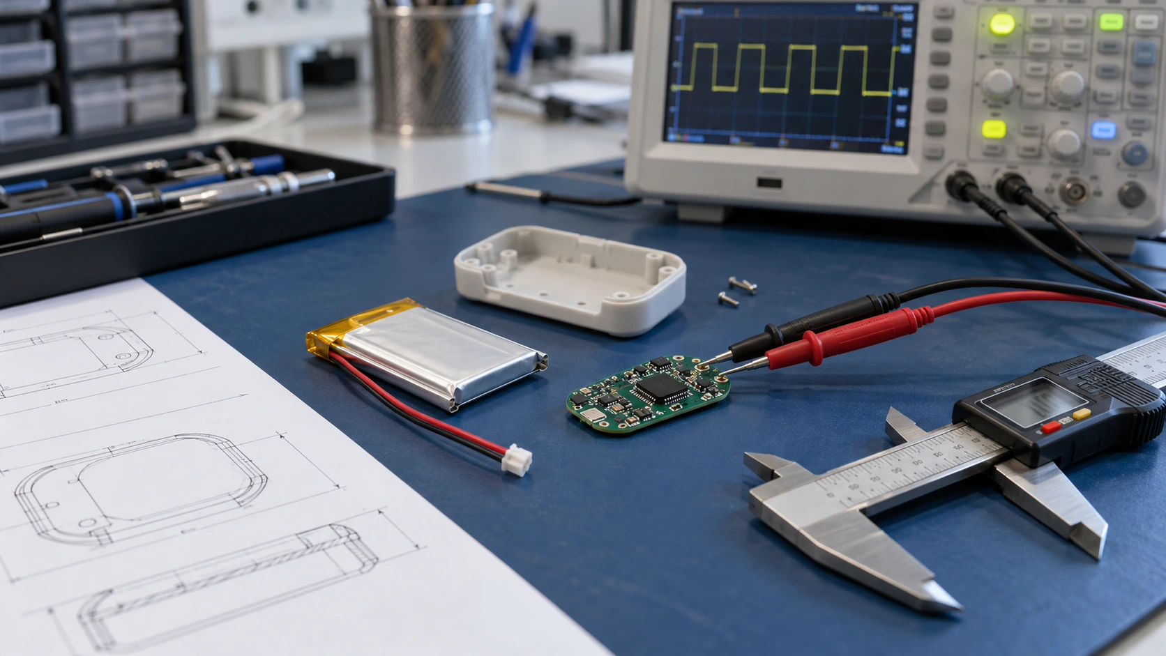

Technical reviewer: Dr. Maximilian Weber
Chief Scientist at THOR Power. Reviews battery safety boundaries, dynamic current validation, charger and protection integration, evidence scope and production release.

Author: Victor Xiong
President, OEM Division & Custom Battery Specialist. Leads OEM battery programs for device brands, product developers and industrial customers.
An OEM engineering guide to finished-pack fit, usable energy, pulse current, charging, protection, evidence boundaries and production release for non-implantable wearable and portable devices
Why Battery Selection Is a System Engineering Decision
OEM teams selecting a LiPo battery for wearable and medical devices should evaluate the complete product boundary, especially for non-implantable body-worn and portable products, rather than only voltage, rated capacity and nominal pouch dimensions. The finished pack must fit the enclosure, supply the real mission profile and pulse load, match the charger and protection architecture, and remain controlled through production. A medical device battery pack can match catalog voltage, capacity and nominal size and still fail because of local mechanical interference, pulse-voltage collapse, an incorrect charge-voltage class, an NTC signal the host does not interpret correctly, or a compliance assumption made at the wrong system level.
Scope. This guide applies to rechargeable lithium-ion pouch packs used in non-implantable body-worn and portable devices, including wellness products and regulated medical electrical equipment where relevant. It does not cover implantable battery systems, primary batteries or a complete regulatory determination for any final device.
Terminology. In this guide, LiPo means a rechargeable lithium-ion cell in a flexible polymer pouch format. The term describes the package format used by the market; it does not remove the need to verify the exact cell chemistry, voltage class, charging limit and manufacturer specification.
Engineering conclusion. Approve a controlled battery assembly against the minimum usable enclosure, the device’s actual electrical limits, the installed environment and the production configuration. Rated mAh alone cannot establish fit, runtime, pulse margin or final-device safety.
Quick Answer
Approve four linked boundaries before releasing the pack:
Mechanical fit: maximum finished dimensions, local PCM and connector features, pressure points and installation clearance.
Energy and power: usable energy, continuous load, pulse width and repetition, and minimum PCB voltage in the device.
Charging and protection: exact cell voltage class, charger target, PCM thresholds, NTC architecture and recovery behavior.
Evidence and production: battery safety evidence, transport testing, final-device requirements and a controlled production configuration.
Evidence boundary. IEC 62133-2 addresses portable lithium battery safety within its scope. UN 38.3 addresses transport. IEC 60601 applies at the final medical electrical equipment level where relevant. These evidence layers are not interchangeable certifications.
Contents
- 1. Define the Use Case and Risk Boundary
- 2. Design the Finished Pack Around the Body-Worn Enclosure
- 3. Size Usable Energy From the Mission Profile
- 4. Validate Pulse Current and Brownout Margin in the Device
- 5. Control Charging, NTC, Protection and the Connector as One System
- 6. Validate the Installed Body-Worn Environment
- 7. Separate Battery Safety, Transport and Medical-Device Evidence
- 8. THOR Power Engineering Example: 520mAh Wearable Transmitter
- 9. Validate Production-Intent Samples and Control Changes
- 10. Information to Send With an Engineering RFQ
- 11. Engineering Decisions to Freeze Before Release
- 12. Frequently Asked Questions
- 13. Technical References
1. Define the Use Case and Risk Boundary
Wearable and medical describe product use; they do not define a battery specification. A wrist-worn wellness sensor, a body-worn transmitter, a home-care monitor and regulated medical electrical equipment can all use compact rechargeable lithium packs, but the consequence of power loss, charging behavior and verification burden differ. Start by classifying the intended use and deciding whether an interruption is merely inconvenient or can affect a safety-related function.
Before discussing capacity, define the use location, the consequence of power loss, operation while charging, service or replacement method, target market and final-device classification. These inputs determine the required electrical margin and which evidence belongs at battery level, pack level and final-device level.
| Question to freeze | Engineering definition | Why it changes the battery decision |
|---|---|---|
| Intended use | Body-worn, handheld, home-use, portable monitoring, therapy support or general wellness | Sets the real operating environment and the consequence of a battery interruption. |
| Power-loss consequence | Benign reset, lost data, missed transmission, alarm interruption, loss of essential performance | Determines how much brownout and end-of-discharge margin is necessary. |
| Charging mode | Charge only when idle, docked charging, USB charging, or operation while charging | Changes thermal conditions and charger/protection verification. |
| Battery service model | Sealed-in, service replaceable or user replaceable | Changes enclosure, connector, labeling and maintenance assumptions. |
| Regulatory boundary | Regulated medical device, medical accessory, wellness product or other electronics | Prevents battery documentation from being confused with final-device compliance. |
Engineering boundary. Do not begin with a capacity request such as 500mAh. Begin with intended use, the consequence of power loss, the real duty cycle and the final-device risk boundary. Capacity becomes meaningful only after those conditions are defined.
For custom pouch architecture and early engineering review, see the Custom LiPo Battery page after the device constraints are defined.
2. Design the Finished Pack Around the Body-Worn Enclosure
Nominal cell size is not finished-pack size. The finished assembly may add a PCM, folded tabs, weld and insulation stack-up, lead wires, connector housing, NTC lead, label and adhesive. In a thin wearable, the controlling dimension may be a small local feature at the protected end rather than the center of the pouch.
The enclosure also needs to be evaluated as a real 3D installation, not a rectangular bounding box. Body-side curvature, screw bosses, ribs, antenna keep-outs, PCB edges, connector latch height, harness bend space and wire exit direction can consume the margin that appears available in a nominal L × W × T comparison.
Use the LiPo Battery Dimensions Guide for nominal pouch geometry and the Finished Battery Size Guide when translating a cell into a protected, wired production pack.
| Finished-pack feature | Where it affects fit | What to verify |
|---|---|---|
| PCM / protection board | Local length or local thickness | Maximum built stack-up, insulation and clearance to the enclosure wall. |
| Folded tabs / weld area | Protected end geometry | No concentrated pressure or sharp enclosure feature over the tab region. |
| Lead wires | Routing volume and bend area | Exit direction, strain relief, practical bend path and no pinching. |
| Connector body / latch | Local height and insertion path | Mating access, latch clearance and assembly sequence. |
| NTC / third wire | Harness route | Sensor architecture, wire identification and strain relief. |
| Adhesive / foam / label | Thickness and local pressure | Controlled material thickness and no enclosure compression used to force fit. |
Mechanical limit. Do not place a flexible pouch cell where the product structure expects repeated bending or concentrated compression. If the enclosure must squeeze the pouch, PCM or harness to close, the mechanical design is not ready for approval.
Sweat, condensation, skin proximity and cleaning exposure are system requirements. They must not be converted into an unsupported claim that the battery itself is waterproof, sweat-proof or chemically resistant. The final enclosure and sealing strategy must provide the required environmental protection.
Need an Engineering Review for a Tight Wearable Enclosure
Send the cavity drawing, hard keep-outs and the dimension that cannot change. THOR Power can screen the finished-pack envelope before samples are built.
3. Size Usable Energy From the Mission Profile
Wearable and portable medical products often spend most of their time at low current, then wake for sensing, processing, radio transmission, display, haptic feedback or an alarm. That means the average load is determined by a repeating mission profile rather than one steady current.
Mission profile. sleep → sensing → processing → radio → display or haptic or alarm → sleep
A first energy estimate should integrate current over each operating state and include the actual charger policy, device cutoff and expected user behavior. Then add the conditions that reduce usable energy in practice: low temperature, aging, internal resistance growth, high-current pulse periods, regulator efficiency and the device’s minimum operating voltage.
| Mission-profile item | Buyer input | Why it matters |
|---|---|---|
| Standby / sleep | Current and total time per cycle | Often dominates long-duration devices even when the current is small. |
| Sensing / processing | Current, duration and repetition | Sets recurring baseline energy use. |
| Radio | TX/RX current, retries, connection interval and worst-case retry behavior | Can add both energy demand and high pulse current. |
| Display / haptic / alarm | Current, duration and activation frequency | May create a short but important peak and user-dependent energy demand. |
| Cutoff / regulator | Minimum device input voltage and regulator behavior | Defines how much of rated cell capacity is actually usable by the product. |
| Aging / temperature | End-of-life runtime target and minimum operating temperature | Prevents beginning-of-life room-temperature capacity from being treated as lifetime runtime. |
Energy boundary. Nominal mAh is not the same as usable device energy. Approve runtime at the device cutoff, temperature, aging condition and duty cycle that apply to the product.
For compact low-capacity projects, the Small Capacity LiPo Batteries page can be used for model discovery only after the mission profile and maximum finished envelope are defined.
4. Validate Pulse Current and Brownout Margin in the Device
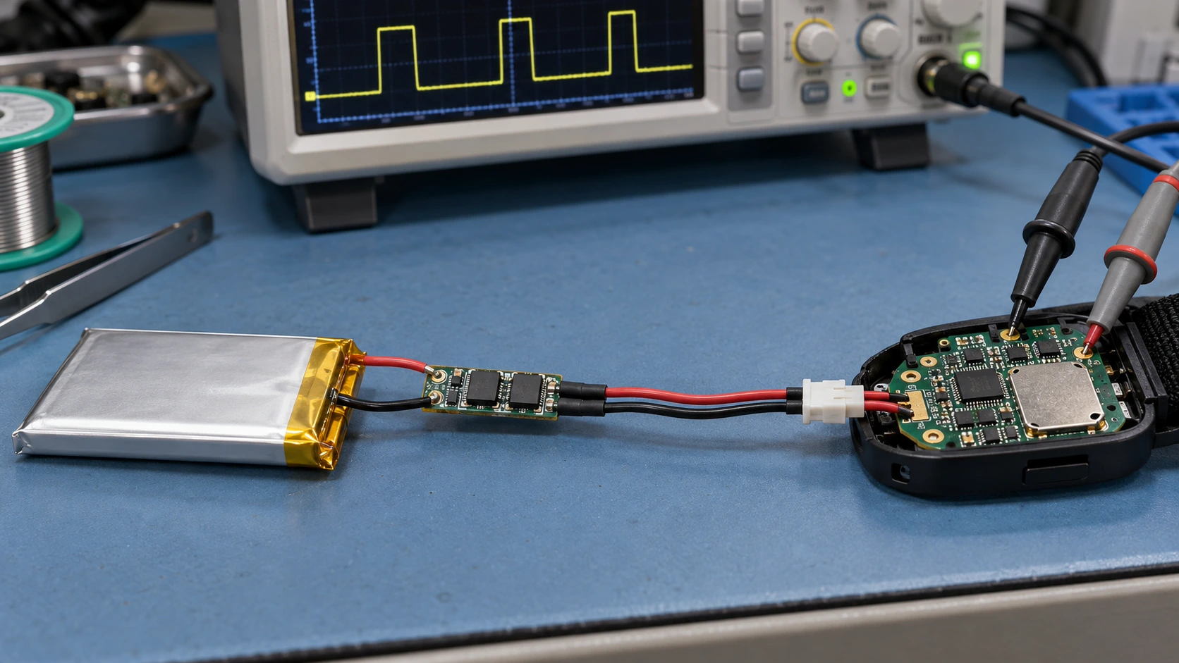
A wearable can meet its average-current budget and still reset during a radio burst, motor pulse, backlight event or alarm. The pass condition is therefore the voltage that reaches the PCB during the real pulse, not simply a current divided by nominal capacity.
Pulse voltage path. VPCB,min = Vcell,pre − ΔVcell,dynamic − ΔVpack-path − ΔVhost-interface
Pass condition. VPCB,min ≥ Vbrownout + Vmargin
Vcell,pre is the cell voltage immediately before the pulse. ΔVcell,dynamic is the transient cell sag. ΔVpack-path includes PCM FETs, welds and battery lead resistance. ΔVhost-interface includes the mating connector, PCB contact and other device-side path losses. The same nominal current can therefore produce a different PCB voltage at different state of charge, temperature, age, pulse width and repetition.
Lithium-ion cell resistance depends on the measurement timescale. Validation should use a pulse duration and repetition pattern that represent the protected device event; a resistance value measured under a different timescale is not universal proof [1].
For a broader current-validation framework, see the High-Discharge LiPo Battery Guide.
| Validation variable | Minimum condition to define | Failure mode if omitted |
|---|---|---|
| State of charge | Lowest SOC at which the pulse must still work | A pack passes at full charge but resets near end of discharge. |
| Temperature | Lowest and highest relevant installed temperatures | Cell resistance and voltage sag are understated at room temperature. |
| Pulse duration | Real event width, not only peak amperes | A very short screen is used to justify a longer load. |
| Repetition | Burst count / interval / retry pattern | Recovery time is overestimated. |
| Aging | Production target and end-of-life condition | New samples pass while aged packs lose voltage margin. |
| Device threshold | Measured or controlled brownout / reset threshold | The battery is judged without the final PCB limit. |
Proof boundary. C-rate arithmetic defines a screening request; it does not prove device operation. Validate a 2.5C pulse request at the actual pulse width, repetition, state of charge, temperature, aging condition, installed electrical path and device threshold.
5. Control Charging, NTC, Protection and the Connector as One System
The cell voltage class, charger target, charger accuracy, protection thresholds and host firmware must agree. A 4.20V-class cell must not be silently replaced by a 4.35V-class cell, or vice versa, without checking the complete charging and fuel-gauge assumptions. A higher voltage class is a different electrochemical operating limit, not a free capacity upgrade.
For this boundary, cross-check the 4.2V vs 4.35V Lithium Battery guide before freezing the charger target.
| Subsystem | What must be controlled | Typical integration error |
|---|---|---|
| Cell | Exact voltage class, charge current limit, discharge current capability and temperature limits | A catalog-equivalent cell is assumed to be electrically interchangeable. |
| Charger | Target voltage, current, tolerance, termination behavior and operation while charging | Nominal charger voltage is checked but accuracy and system heat are not. |
| PCM / BMS | Overcharge, over-discharge, over-current behavior, FET resistance and recovery | Protection is selected only by current label without checking threshold behavior. |
| NTC | Thermistor value/B-constant if applicable, physical location, wiring and host interpretation | A third wire exists but the host does not implement a defined temperature safety policy. |
| Gauge | Cell profile, cutoff, learning/compensation strategy and age behavior | State-of-charge reporting is assumed to follow rated mAh. |
| Connector / harness | Pinout, polarity, wire gauge, lead length and mating interface | Electrical loss or polarity is discovered after enclosure tooling. |
NTC boundary. An NTC lead alone is not a complete safety function. Define the sensor location, thermistor characteristic, host interpretation, charge and discharge response, and recovery behavior as one system.
Connector body, pinout and lead-wire choices should be frozen with the LiPo Battery Connector Types Guide rather than treated as a late purchasing detail.
6. Validate the Installed Body-Worn Environment
A pack inside a body-worn product sees a different environment from a free battery on a laboratory bench. Body heat, clothing, enclosure insulation and charging losses can raise local temperature. Daily motion can flex the harness or strain the connector. Sweat, condensation and cleaning exposure can challenge the enclosure. Operation while charging can combine device heat and charge heat in the same small volume.
| Installed condition | What to verify | System-level question |
|---|---|---|
| Body heat + clothing | Steady-state cell and local PCM temperature | Does the enclosure trap heat during the longest expected use period? |
| Use while charging | Combined charger and device load temperature | Is the product allowed to operate at full function while charging? |
| Daily motion | Wire exit, strain relief and connector retention | Can repeated motion concentrate force at the pouch tab or connector? |
| Condensation / sweat | Enclosure sealing and material compatibility | What protects the battery and PCB from moisture exposure? |
| Cleaning | Cleaning method and allowed chemicals at final-product level | Can cleaning fluid reach the battery cavity or adhesive system? |
| User pressure / impact | Mechanical protection around pouch surfaces | Can normal wear create concentrated compression or bending? |
Installed validation rule. Validate the battery in the product configuration, not only as a free battery on a laboratory bench.
7. Separate Battery Safety, Transport and Medical-Device Evidence
Battery safety evidence, dangerous-goods transport evidence and final medical-device compliance answer different questions. UN 38.3 is a transport test regime, not a complete product safety certification. IEC 62133-2 addresses portable sealed secondary lithium cells and batteries within its scope, while IEC 60601-1 applies to medical electrical equipment where relevant [2]–[5].
| Evidence layer | Reference | What it addresses | What it does not prove by itself |
|---|---|---|---|
| Portable lithium battery safety | IEC 62133-2:2017 + AMD1:2021 | Safety requirements and tests for portable sealed secondary lithium cells and batteries within scope. | Final medical electrical equipment compliance or product essential performance. |
| Transport | UN Manual of Tests and Criteria Rev.8 (2023) + Amendment 1 (2025), subsection 38.3 | Transport test requirements for lithium cells and batteries. | A complete battery product safety approval or medical-device approval. |
| Medical electrical equipment | IEC 60601-1:2005 + AMD1:2012 + AMD2:2020 | Basic safety and essential performance of medical electrical equipment within scope. | A standalone cell or pack certificate that substitutes for final-equipment assessment. |
| Home healthcare environment | IEC 60601-1-11:2015 + AMD1:2020, where applicable | Additional requirements for medical electrical equipment/systems used in the home healthcare environment. | A universal requirement for every wearable or every battery. |
| Medical-device risk management | ISO 14971:2019 | Risk-management process for medical devices, including battery-related hazards within the final-device context. | Final-device conformity, validation of the customer’s risk controls or automatic approval of a battery configuration. |
| Biological evaluation | ISO 10993-1:2025 | Requirements and principles for biological evaluation of medical-device materials within a risk-management process. | Automatic testing of the internal battery when the battery has no relevant body-contact exposure. |
Compliance boundary. Do not market a battery as medical certified merely because IEC 62133-2 or UN 38.3 documentation is available. State the exact battery-level evidence and identify final-device standards and regulatory work separately.
For regulated medical devices, the final device manufacturer should address battery-related hazards within the ISO 14971 risk-management process. Relevant hazards can include loss of essential performance, unexpected shutdown, charging faults, thermal events, connector failure and reasonably foreseeable misuse [6]. THOR Power can provide battery-level engineering evidence and test support; the device manufacturer remains responsible for final-device risk management, verification and regulatory decisions.
For skin-worn products, biological evaluation depends on which final-device materials contact the body, the contact type and the contact duration. When the battery remains sealed behind a controlled enclosure and is not a contacting material, ISO 10993-1 should not be converted into an automatic requirement to test the internal battery [7]. The final-device manufacturer should define the contact boundary and evaluation plan.
Regulatory boundary. Applicable standards and regulatory requirements depend on the complete device, intended use, target market and risk classification. The references in this guide support engineering decisions; they are not an exhaustive conformity assessment or regulatory determination.
8. THOR Power Engineering Example: 520mAh Wearable Transmitter
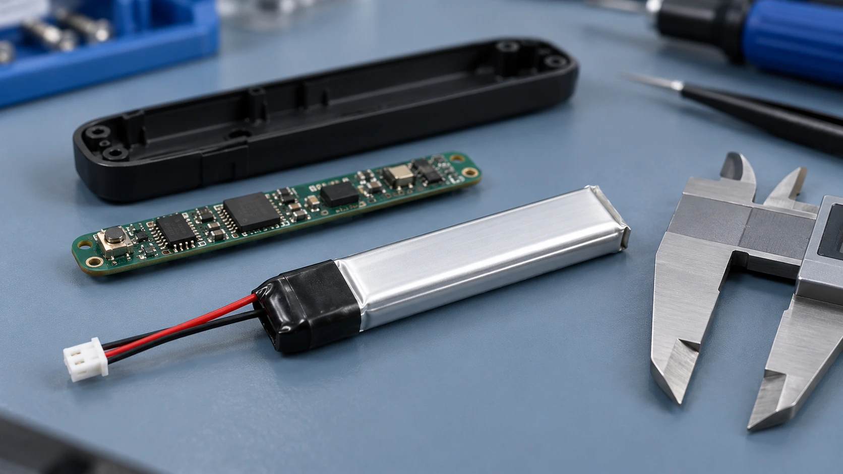
The following example uses real THOR Power project inputs to show how a pulse request should be framed. It does not publish a customer pass or field result and should not be read as a released performance claim for THOR-701349 or any other model. The example is therefore a design and validation framework, not a completed public performance case study.
| Project item | Known project data |
|---|---|
| Application | 406 MHz wearable transmitter |
| Battery | THOR-701349 |
| Capacity | 520mAh |
| Finished pack dimensions | Approximately 51 × 13 × 7 mm with PCM |
| Peak requirement | Approximately 1.3A |
| Project calculation reference (0.5C) | 0.26A |
| Project calculation reference (1C) | 0.52A; not a released continuous-current rating |
| Initial screening calculation (3C) | 1.56A; not a released operating limit |
The screening calculation is 1.3A / 0.52Ah, or approximately 2.5C. A 3C comparison equals 1.56A, but this value was used only to frame an initial engineering request. It is not an approved continuous-current rating or pulse-current limit. Release still depends on the defined waveform, installed voltage path and device threshold.
Validation record required. For a publishable performance result, record the sample configuration and quantity, state of charge, conditioning temperature, pulse width, repetition pattern, wire and connector path, measurement points, device brownout threshold, acceptance criterion and observed result. These data are not added here because the customer result has not been documented for publication.
Pulse duration: how long the approximately 1.3A event lasts.
Repetition: how frequently the pulse repeats and whether retries create burst trains.
Lowest SOC: the minimum state of charge at which the transmitter must still complete the event.
Temperature: the lowest installed temperature relevant to use.
Cell voltage sag: the transient voltage drop during the real pulse.
PCM behavior: voltage drop, over-current behavior and recovery.
Connector and wire drop: loss through the finished harness and mating interface.
Device brownout threshold: the minimum PCB voltage needed to complete the event without reset.
Evidence boundary. The 0.5C, 1C and 3C figures are calculation references for THOR-701349, not released operating limits and not ratings for other THOR batteries. Approval still requires defined pulse width, repetition, state of charge, temperature, aging condition, installed voltage path and device threshold. No customer pass or field result is claimed.
9. Validate Production-Intent Samples and Control Changes
A successful engineering sample proves that one built configuration can work under the conditions tested. It does not automatically define the production reference. Before release, the battery BOM and assembly route need to be frozen closely enough that later substitutions do not change fit, voltage drop, protection behavior or thermal response.
| Production item | Control to freeze before release | Why the change matters |
|---|---|---|
| Cell construction | Exact approved cell build and supplier-controlled specification | Changes capacity, resistance, thickness and pulse behavior. |
| PCM / FET | Board layout, protection IC, FETs and thresholds | Changes voltage drop and protection behavior. |
| NTC | Part, characteristic, location and wiring | Changes measured temperature and host response. |
| Wire | Gauge, length, insulation and exit direction | Changes voltage drop, routing and strain. |
| Connector | Housing, terminal, pinout and polarity | Changes mating, fit and interface reliability. |
| Insulation / label / adhesive | Material type, thickness and placement | Changes finished dimensions, pressure and thermal path. |
| Assembly route | Tab fold, PCM position, weld, strain relief and final wrapping | Changes local stack-up and repeatability. |
| Production test | Electrical and dimensional checks plus acceptance limits | Turns an engineering sample into a controlled release process. |
| Change control | Approval path for cell, PCM, harness or material substitutions | Prevents an unreviewed change from invalidating device verification. |
Production release boundary. A successful engineering sample is not a production reference. Release must be tied to controlled materials, assembly details, acceptance tests and change control.
Use the Battery Pack Prototype Testing and Validation guide when moving from engineering samples to production-intent validation.
10. Information to Send With an Engineering RFQ
A useful RFQ gives the battery engineer enough information to test actual constraints rather than infer them from a capacity target. In THOR Power’s project workflow, early confirmation of the hard mechanical dimension, pulse waveform, charger architecture and documentation boundary reduces avoidable sample revisions.
| RFQ group | Information to provide |
|---|---|
| Product and market | Device type; intended use; target market; regulated medical device or wellness product. |
| Mechanical envelope | Minimum usable cavity; maximum finished T × W × L; hard keep-outs; curved surfaces; pressure points; assembly path. |
| Runtime | Target runtime; duty cycle; standby/sensing/radio/display/alarm pattern; device cutoff voltage. |
| Current | Continuous current; pulse current; pulse duration; repetition or retry pattern; lowest SOC for the pulse. |
| Temperature | Operating, charging and storage temperature relevant to the installed device. |
| Charging | Charger voltage/current; charger architecture; use-while-charging behavior; charge termination assumptions. |
| Protection and sensing | PCM/BMS requirement; NTC requirement; host interpretation; recovery behavior. |
| Harness | Connector; pinout; polarity; wire gauge; lead length; wire exit direction. |
| Environment / life | Body-worn exposure, condensation/cleaning boundary, mounting method, life target and end-of-life runtime. |
| Program | Prototype quantity; forecast volume; required drawings, datasheets, UN 38.3 / IEC 62133-2 or other documentation needs. |
First buyer input. Send the battery cavity drawing with maximum finished thickness, width and length, hard keep-outs and the dimension that cannot change. Then provide the actual peak-current waveform and charger target.
11. Engineering Decisions to Freeze Before Release
Define intended use, the consequence of power loss and the final-device risk boundary before choosing capacity.
Approve the maximum finished pack against the minimum usable enclosure, including PCM, connector, harness and local stack-up.
Approve runtime and pulse margin at the relevant state of charge, temperature, aging condition and device cutoff.
Freeze the cell voltage class, charger, protection thresholds, NTC behavior, gauge assumptions and interface as one controlled system.
Separate battery safety, transport and final medical-device evidence; state the scope of each document precisely.
Release only a production-intent configuration tied to controlled materials, assembly instructions, acceptance tests and change control.
The release decision should follow one traceable chain: intended use → finished mechanical envelope → usable energy → pulse voltage at the PCB → charger, protection and sensing behavior → installed environment → evidence scope → controlled production configuration.
Defining this chain early can reduce avoidable enclosure interference, unrealistic runtime assumptions and unsupported compliance claims. Final approval still depends on evidence from the controlled pack and the complete device.
Need an Engineering Review for Your Battery Project
Send the enclosure drawing, runtime target, continuous and pulse load, charger details, connector requirements and documentation needs for an engineering review.
12. Frequently Asked Questions
What information is needed to select a wearable or medical device battery?
Start with the minimum usable cavity, maximum finished pack dimensions, mission profile, device cutoff, continuous and pulse load, charger target, operating temperature, connector and required evidence. A model cannot be approved from nominal mAh and pouch dimensions alone.
Does a medical device need IEC 62133-2 battery evidence?
IEC 62133-2 covers portable sealed secondary lithium cells and batteries within its scope. Whether the evidence is required depends on the device, target market, applicable standards and conformity strategy. It does not replace final medical-device assessment.
Is UN 38.3 a battery safety certification?
No. UN 38.3 is the lithium cell and battery transport test regime in the UN Manual of Tests and Criteria. It supports transport compliance; it is not a complete product safety certification or medical-device approval.
Does every wearable battery need an NTC wire?
No. The need for an NTC depends on the charger, host electronics, temperature-risk strategy and product requirements. When an NTC is used, define its characteristic, location, wiring, host thresholds, response and recovery behavior.
Can I choose the thinnest cell with the highest mAh?
Catalog capacity and nominal cell thickness do not establish suitability. PCM stack-up, swelling allowance, connector geometry, pulse resistance, charger compatibility and production tolerance can control the design. Approve the finished pack and the actual operating profile.
Does ISO 10993-1 apply to a skin-worn medical device battery?
Not automatically. ISO 10993-1 applies to biological evaluation of medical-device materials within the final product’s contact-risk framework. If the battery is sealed behind an enclosure and is not a contacting material, the device manufacturer should determine which final-device materials and exposures require evaluation.
13. Technical References
- [1] Barai, A., Uddin, K., Widanage, W. D., McGordon, A. and Jennings, P. A study of the influence of measurement timescale on internal resistance characterisation methodologies for lithium-ion cells. Scientific Reports 8, 21 (2018).
- [2] IEC 62133-2:2017+A1:2021. Secondary cells and batteries containing alkaline or other non-acid electrolytes — Safety requirements for portable sealed secondary cells, and for batteries made from them, for use in portable applications — Part 2: Lithium systems. IEC 62133-2 official publication.
- [3] United Nations Manual of Tests and Criteria, Revision 8 (2023), Amendment 1 (2025), subsection 38.3 for lithium cells and batteries. UNECE Revision 8 files.
- [4] IEC 60601-1:2005+A1:2012+A2:2020. Medical electrical equipment — Part 1: General requirements for basic safety and essential performance. IEC 60601-1 official publication.
- [5] IEC 60601-1-11:2015+A1:2020. Medical electrical equipment — Part 1-11: Requirements for medical electrical equipment and medical electrical systems used in the home healthcare environment. IEC 60601-1-11 official publication.
- [6] ISO 14971:2019. Medical devices — Application of risk management to medical devices. ISO 14971 official publication.
- [7] ISO 10993-1:2025. Biological evaluation of medical devices — Part 1: Requirements and general principles for the evaluation of biological safety within a risk management process. ISO 10993-1 official publication.
Related Engineering Guides
- Custom LiPo Battery Prototyping: From Device Requirements to Mass Production
- High-Discharge LiPo Battery: How to Validate Continuous, Peak and Pulse Current
- How to Maximize Usable Energy in a Small Custom LiPo Battery
- LiPo Battery Dimensions Guide
- LiPo Battery Connector Types: How to Choose Pitch, Wire and Polarity