LiPo Battery Dimensions: How to Choose the Right Size for Your Device

Technical reviewer: Dr. Maximilian Weber
Chief Scientist at THOR Power. Reviews battery engineering content for technical accuracy, test boundaries and production relevance.

Author: Victor Xiong
OEM Division President at THOR Power, focused on custom lithium battery development and manufacturing for device programs.
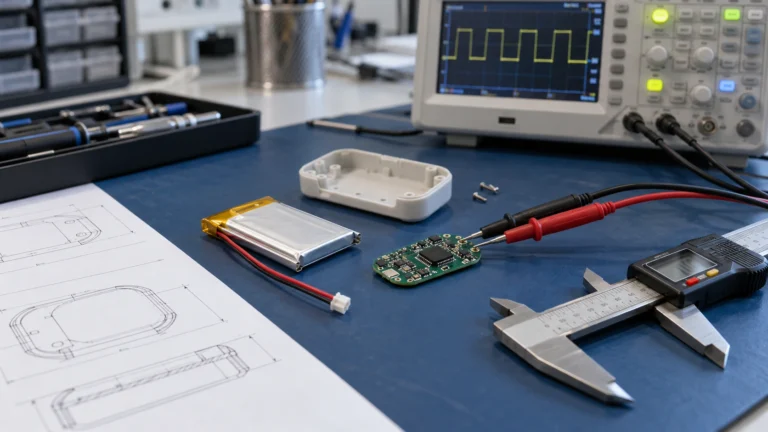
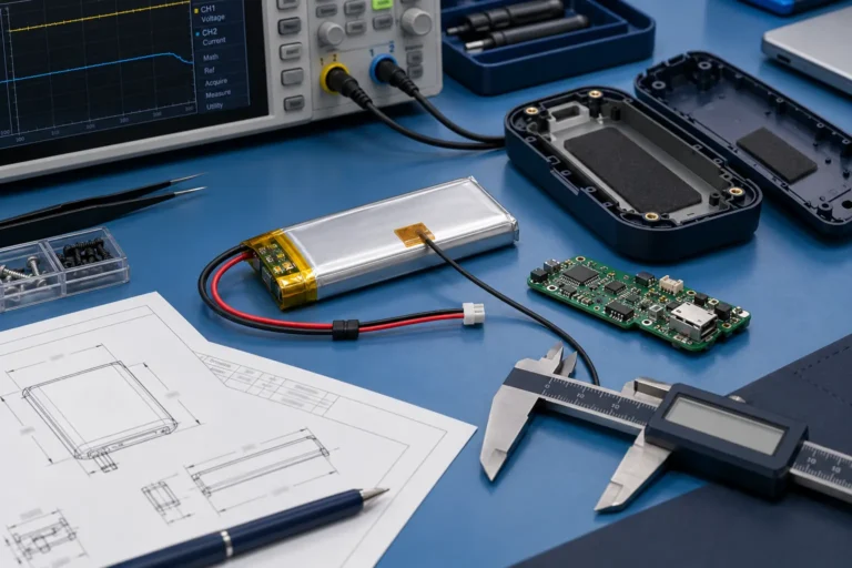
An OEM engineering guide to LiPo battery dimensions, finished-pack size, local keep-outs, measurement control and production release.
Quick Answer
Quick Answer
Start with the minimum usable device cavity, define hard axes and local keep-out zones, and calculate the maximum physical envelope of the finished battery dimensions. Keep physical pack dimensions separate from installation clearance: derive the finished-pack maximum from the bare-cell maximum plus the actual axis-specific assembly stack-up and local feature envelopes; fit margin = cavity minimum − finished-pack maximum − required installation/service clearance. Approve the design only when every global and local margin is non-negative and the pack also meets current, thermal, life and sample-validation requirements.
THOR POWER SUPPLY SCOPE
THOR Power supports custom LiPo pouch cells and finished battery packs by matching cavity dimensions, capacity, voltage class, continuous/peak current, PCM/NTC, connector, wire length, label and mechanical stack-up. Final dimensions, tolerance and clearance are confirmed for the exact project configuration rather than inferred from a generic catalog code.
Four Approval Questions Before Choosing LiPo Battery Dimensions
- Does the released finished-pack envelope fit the minimum usable device cavity, including PCM, tabs, tape, wires, connector and local keep-outs?
- Have thickness, width and length been defined as nominal, maximum, bare-cell or finished-pack dimensions under a stated measurement condition?
- Can the candidate geometry still meet usable capacity, pulse current, voltage-sag, thermal and life requirements?
- Is the production drawing controlled well enough that future lots, connectors and PCM revisions cannot silently change the fit?
At a Glance: LiPo Dimension Decisions
| Decision layer | What to check | Why it matters |
|---|---|---|
| Device cavity | Minimum usable T×W×L, hard axes and local keep-outs. | Prevents approving a cell that fits only the nominal CAD space. |
| Finished-pack envelope | PCM, folded tabs, insulation, label, wires, connector and local high points. | Defines the real object installed in the product. |
| Measurement condition | SOC, temperature, rest time, datum, contact method and maximum/nominal basis. | Makes sample and lot comparisons repeatable. |
| Electrical load | Capacity, usable Wh, continuous current, pulse current and cutoff voltage. | A smaller cell can pass size but fail power or runtime. |
Table of Contents
- 1. Start With the Device Cavity, Not the Battery Catalog
- 2. Understand What LiPo Battery Dimensions Actually Describe
- 3. Build the Finished-Pack Envelope Before Applying Cavity Clearance
- 4. Treat Thickness as a Condition-Dependent Dimension
- 5. Balance Capacity Against Thickness, Width and Length
- 6. Check Current Capability Before Locking the Geometry
- 7. Reserve Space for Tabs, PCM, Wires and Connector Orientation
- 8. Use a LiPo Dimensions Database Without Creating a False Fit
- 9. Control Measurement and Release a Production-Ready Drawing
- 10. Decide What to Change When No Candidate Fits
- 11. Send the Right Inputs and Require the Right Outputs
- 12. FAQ: LiPo Battery Dimensions
1. Start With the Device Cavity, Not the Battery Catalog
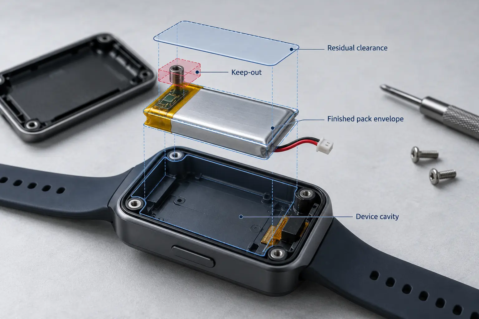
The most common sizing mistake is to begin with a battery model and then try to make the enclosure accept it. For an OEM product, the direction should be reversed. Freeze the usable cavity first: the volume that the finished battery pack is actually allowed to occupy after PCB, speaker, antenna, screw boss, rib, foam, thermal barrier and assembly access are considered. A CAD cavity dimension is not automatically a battery dimension.
Separate each axis into a hard limit and a negotiable limit. A thickness may be hard because the battery sits between a PCB and display, while length may be more flexible because a foam stop can move. Also define local keep-out zones. A connector body may fit inside the overall bounding box but collide with a housing rib, and a wire may require a turning corridor that does not appear in a simple T × W × L value.
| Device input | Engineering interpretation | Failure if omitted |
|---|---|---|
| Minimum usable cavity (worst case) in T × W × L | The true envelope available to the finished pack, not the external enclosure size. | A catalog cell fits on paper but the assembled pack interferes with PCB, housing or display. |
| Hard vs flexible dimensions | Identify axes that cannot be exceeded and axes that can trade against each other. | The supplier optimizes the wrong dimension and loses usable capacity. |
| Keep-out zones and local obstacles | Reserve space for screws, ribs, speakers, antennas, sensors and sharp edges. | Local collision or pouch abrasion even though global dimensions fit. |
| Assembly path | Define whether the battery drops in, slides in, bends around a feature or is installed before another component. | The pack fits in final CAD but cannot be physically assembled. |
| Service / replacement requirement | Define pull-tab, adhesive, connector access and removal path. | A prototype works but field replacement damages the pouch or wiring. |
FIT RULE
Release the battery against the worst-case usable cavity, not the nominal enclosure volume. The device drawing should show hard limits, keep-out zones, installation direction and any surface that may contact the pouch.
2. Understand What LiPo Battery Dimensions Actually Describe
For pouch cells, suppliers commonly describe three principal dimensions: thickness (T), width (W) and length (L). THOR Power uses nominal T × W × L shorthand in many six-digit cell model numbers. For example, a 603040 cell is approximately 6.0 × 30 × 40 mm at the bare-cell level. This shorthand is useful for search and screening, but it is not a mechanical release drawing and it should not be assumed to be universal across suppliers.
IEC 61960-3:2017 is useful here because it explicitly covers dimensions for portable lithium cells and includes an informative annex on measuring laminate-film cell thickness and width. [1] The standard reinforces a core engineering point: dimensions must be tied to a defined cell type and measurement method. A model code alone does not tell you whether tabs, seals, protective tape or a finished-pack assembly are included.
| Dimension term | What it should mean in a controlled drawing | What must be clarified |
|---|---|---|
| Cell-body thickness | Thickness across the active pouch body at defined SOC, temperature, rest and measurement method. | Nominal, typical or maximum? What preload/contact method is used? |
| Cell-body width | Maximum body/seal width across the controlled region. | Are side seals, folded edges or local steps included? |
| Cell-body length | Controlled pouch body length to the defined datum. | Does it include the top seal or tab root? |
| Tab projection | Positive/negative tabs extending beyond the pouch body. | Tab length, width, spacing, polarity and whether tabs are folded. |
| Finished-pack envelope | Maximum local T/W/L after PCM, tape, label, wire and connector integration. | Where are local maxima and which features are excluded from the bounding box? |
| Global finished-pack envelope | Smallest rectangular T/W/L box that contains the production-intent pack features defined as part of the pack. | Does it include the connector, free wire length or only the pack body? Which local maximum controls each axis? |
| Local feature / keep-out envelope | A dimensioned zone for a PCM step, folded tab, wire bend, connector latch or other non-uniform feature. | Can the feature clear ribs, PCB components and the installation path even when the global box fits? |
| Minimum usable device cavity | The smallest available cavity after enclosure tolerance, adjacent components and local obstacles are considered. | Is it a measured minimum, a nominal CAD value or an enclosure maximum-material condition? |
MODEL-CODE GATE
Treat 603040, 701349 or any similar pouch-cell code as a search key, not as the final mechanical definition. Approval requires a controlled drawing that identifies the measurement datum, body and seal boundaries, tab projection, PCM location, wire exit, connector keep-out, global bounding envelope and any local maximum that can contact the device.
3. Build the Finished-Pack Envelope Before Applying Cavity Clearance
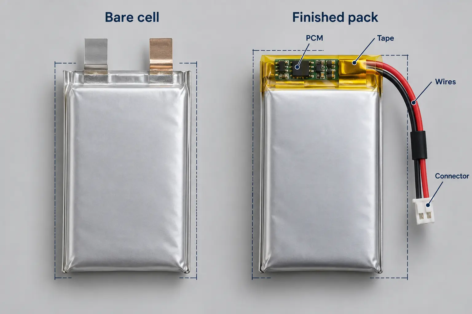
A bare pouch cell and a finished battery pack are different mechanical objects. The cell is only the electrochemical core plus laminate pouch and tabs. A production pack may add a PCM, MOSFETs, fuse or PTC, NTC, nickel connection, insulation paper, adhesive tape, foam, label, lead wires and connector. Each part affects a different axis, and the largest local stack-up may occur only near the tab end rather than across the whole cell surface.
| Added feature | Dimension most often affected | Engineering question |
|---|---|---|
| End-mounted PCM | Length; sometimes local thickness | How far does the board/insulation extend beyond the pouch body, and is there a local step? |
| Side-mounted PCM | Width and/or thickness | Does moving the board sideways solve length but create a width or pressure problem? |
| Folded tabs / nickel weld | Length and local thickness | What is the tab fold radius and insulation stack? |
| Label / protective tape | Thickness; sometimes width/length at overlap | Is the quoted maximum pack size measured after final label and tape? |
| Lead wires | Local thickness and routing volume | Where do wires leave the pack, and can they cross the cell face without creating a pressure point? |
| Connector | Local length/width and assembly path | Is the connector inside the battery cavity or in a separate reserved pocket? |
ILLUSTRATIVE FIT SCREEN
A 603040 bare cell may appear to fit a cavity because the nominal body is about 6.0 × 30 × 40 mm. If the PCM is mounted at the tab end, the finished pack can exceed the available length even though the cell body fits. Moving the PCM to the side may recover length but consume width or create a local thickness step. The correct decision is made from maximum production-intent dimensions and local features, not from the nominal model code.
Worked example: separate pack size from cavity clearance
The values below are illustrative arithmetic only. They demonstrate the decision sequence and must not be used as THOR Power tolerances, PCM allowances or universal clearance requirements.
| Axis | Cavity minimum | Bare-cell maximum | Effective axis addition from pack integration | Pack maximum | Required install clearance | Residual margin |
|---|---|---|---|---|---|---|
| Thickness | 6.80 mm | 6.20 mm | 0.25 mm | 6.45 mm | 0.25 mm | +0.10 mm |
| Width | 32.00 mm | 30.60 mm | 0.40 mm | 31.00 mm | 0.50 mm | +0.50 mm |
| Length | 44.00 mm | 40.50 mm | 2.10 mm | 42.60 mm | 0.80 mm | +0.60 mm |
Decision: the simple axis check is positive, but approval still depends on the PCM step, connector pocket, wire bend, assembly route, charged/aged condition and measured samples. A negative value on any hard axis requires a design change; it should not be waived by averaging the three axes.
Then test the pack against the device: residual fit marginᵢ = minimum usable cavityᵢ − maximum finished-pack envelopeᵢ − required installation/service clearanceᵢ. A preliminary fit passes only when the margin is non-negative for every hard axis and all local keep-out, wire-bend and insertion-path checks also pass. This fit margin is an assembly decision; it is not a safety allowance for abnormal gas generation or an unverified substitute for life-stage dimensional data.
4. Treat Thickness as a Condition-Dependent Dimension
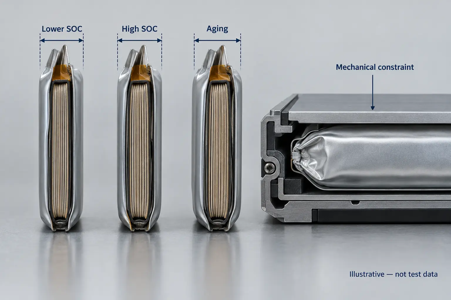
Thickness is usually the most dangerous LiPo dimension to treat as a fixed number. Pouch cells change thickness reversibly with state of charge because electrode materials expand and contract during lithiation and delithiation. They can also grow irreversibly with aging, gas generation and interphase development. The measured value further depends on temperature, rest time, compression and where the gauge contacts the flexible pouch surface.
Published work demonstrates why a universal swelling allowance is not defensible. One pouch-cell study measured reversible thickness changes of about 0.22-0.23 mm during charge/discharge under its specific test conditions. [2] Another study found aged cells to be up to 6.3% thicker than fresh cells at 0% SOC and 14.7% thicker at 100% SOC for the tested cell/aging conditions. [3] These are mechanism examples, not design allowances for another chemistry or cell size. More recent full-field measurements also show that charging-induced swelling can be spatially non-uniform across a pouch surface and changes with rate and applied pressure. [5]
| Dimension state | What to control | Why it matters |
|---|---|---|
| Incoming / BOL thickness | SOC, temperature, rest time, measurement location and contact method. | Creates a repeatable baseline for sample and lot comparison. |
| Fully charged thickness | Defined charge profile and post-charge rest. | Often closer to the worst reversible thickness than a partially charged shipping sample. |
| Aged free thickness | Cycle/storage condition, SOH, SOC and temperature. | Captures irreversible life growth that a new sample cannot show. |
| Constrained behavior | Contact area, preload/pressure, SOC and temperature. | A rigid enclosure can convert thickness growth into force on PCB, display or seals. |
| Local maximum | Multiple measurement points or mapped surface where needed. | Flexible pouches can have edge/center differences; one center reading may miss the limiting point. |
CLEARANCE RULE
Do not publish one universal LiPo clearance number. A provisional gap may be useful during concept screening, but it is not a chemistry-independent swelling specification. Final clearance should be based on measured maximum pack dimensions at defined conditions and, where the enclosure constrains the pouch, on the pressure or force that adjacent components and seals can tolerate.
Keep normal-life fit clearance separate from abuse containment. Space reserved for manufacturing variation, reversible SOC-related dimensional change and project-qualified aging does not prove that an enclosure can safely contain a damaged or gas-generating cell. Abnormal swelling requires a separate product safety and venting assessment rather than a larger number added to the fit equation.
For production drawings, record the measurement condition next to the dimensional limit. If a supplier gives only “6.0 mm thickness” without saying whether the value is nominal or maximum, bare or packed, charged or partially charged, new or aged, and free or constrained, the number is incomplete for mechanical design. Published constant-thickness and constant-stress testing also shows that mechanical constraint changes whether cell evolution appears as displacement or force, so a tight cavity must be evaluated as a mechanical system, not only as a gap. [4]
For a deeper treatment of reversible SOC breathing, aged dimensional growth and constrained-force behavior, see the LiPo pouch-cell swelling guide.
5. Balance Capacity Against Thickness, Width and Length
Higher capacity usually requires more active material or higher usable energy density, but the mechanical trade can be made in different directions. A product with a hard 5 mm thickness limit may gain capacity by using more width or length. Another product may have a fixed footprint but tolerate a thicker pouch. If a semi-solid LiPo option is evaluated, compare its production-intent envelope and usable energy under the same current, thermal, life and swelling limits. The best geometry is the one that maximizes usable device energy inside the actual cavity while preserving those margins.
For first-pass comparison, energy is approximately nominal voltage x capacity, and volumetric screening can compare delivered Wh with the controlled cell or finished-pack volume. But a simple T × W × L box does not fully describe usable active volume: seal width, tabs, electrode loading, current-collector design, chemistry, charge-voltage class and protection architecture all consume or change the energy budget. Two LiPo cells with similar outer dimensions can therefore have different capacity and power behavior.
| Product constraint | Useful optimization direction | Do not assume |
|---|---|---|
| Thickness is fixed | Trade width/length, chemistry platform or electrode loading while preserving power and life. | That the highest mAh in the same thickness is automatically the best cell. |
| Footprint is fixed | Evaluate extra thickness only if the enclosure can tolerate BOL and aged maximums. | That nominal thickness equals installed lifetime thickness. |
| One axis is flexible | Use that axis deliberately to gain capacity or simplify PCM placement. | That all three dimensions should be minimized simultaneously. |
| Runtime is the real target | Compare usable Wh above device cutoff under the actual load and temperature. | That catalog mAh alone predicts mission runtime. |
| High energy density is requested | Confirm Wh/L or Wh/kg basis and exact charge/current limits. | That a high-energy design will also meet high pulse or fast-charge requirements. |
If capacity is the dominant requirement, the LiPo battery capacity and runtime guide should be used together with the mechanical screen. If the project is deciding between 4.20 V and higher-voltage cells, review the 4.2 V vs 4.35 V lithium battery guide; charger compatibility must be treated separately rather than hidden inside a size comparison.
6. Check Current Capability Before Locking the Geometry
The smallest cell that meets capacity is not necessarily the smallest cell that can power the device. Continuous current, peak current, pulse duration, state of charge, temperature and cutoff voltage can force a different geometry or cell construction. Narrow tabs, high internal resistance, aggressive energy loading or poor heat rejection can make a nominally adequate cell sag below the device cutoff during a transmitter burst, motor start or wireless uplink.
This matters especially in wearables, trackers, emergency transmitters and other compact electronics. A 500 mAh cell rated for moderate current and a 500 mAh high-rate cell may need different electrode designs and may not deliver the same capacity, heat rise or thickness behavior under the same duty cycle. Dimension selection and current selection should therefore converge together.
For a tighter application example, see the wearable LiPo battery thickness trade-off workflow.
| Power input | What the battery supplier should confirm | Mechanical consequence |
|---|---|---|
| Continuous current | Current in amperes, voltage sag, heat rise and steady-state limit at defined SOC/temperature. | May require a lower-resistance or larger cell than capacity alone suggests. |
| Peak / pulse current | Peak amperes, pulse duration, repetition, recovery and device-cutoff margin. | May change cell platform, tab design, PCM rating or wire gauge. |
| PCM over-current threshold | Typical/minimum trip behavior and time domain for the exact board. | A capable bare cell can still be blocked by an undersized protection board. |
| Cold operation | Voltage sag and usable energy at the lowest operating temperature. | Extra electrical margin may be needed even when the room-temperature fit is perfect. |
| Heat path | Cell and pack temperature under the real duty cycle. | A zero-clearance enclosure can worsen thermal performance or create local pressure. |
POWER GATE
Freeze the battery cavity only after capacity and load waveform have been screened together. If the device has short high-current events, provide continuous current, peak current, pulse duration, repetition interval and minimum device voltage – not only a C-rate label.
7. Reserve Space for Tabs, PCM, Wires and Connector Orientation
The tab end is often where a technically correct cell becomes an unusable pack. Tabs must be welded or connected, insulated and routed to the protection board. The board then connects to wires or a flex, which must exit in a defined direction. A connector has its own body, latch, mating direction and cable bend requirement. These details can consume more length than the difference between two cell models.
| Integration detail | Drawing requirement | Common field failure |
|---|---|---|
| Positive/negative tab position | Tab spacing, polarity, width, projection and fold direction. | Electrically correct cell cannot be assembled into the existing harness layout. |
| PCM orientation | End/side/back placement and local maximum envelope. | Board fits but creates a hard pressure point against the pouch or housing. |
| Wire exit | Exit side, length, gauge, insulation diameter and routing corridor. | Wire crosses the cell face or forces a bend at the pouch seal. |
| Connector body | Exact housing, pitch, mating direction and reserved connector pocket. | Cell fits but connector cannot mate or collides with enclosure. |
| Polarity / pinout | Wire colors and connector Pin 1 / Pin 2 polarity on controlled drawing. | Mechanical fit passes while reversed pinout damages the device. |
| Label / foam / adhesive | Final material stack and overlap locations. | Production pack becomes thicker than engineering samples. |
If the connector has not yet been frozen, reserve a separate connector keep-out and mating corridor instead of pretending the complete harness is inside the cell-body dimensions. When the connector is known, specify the exact manufacturer series, mating part, latch direction, wire gauge and minimum practical bend route. Review mechanical orientation, pinout and wire exit together because changing one can force a different PCM location or battery orientation. The drawing should distinguish the pack's controlled bounding envelope from flexible wire sweep and service-access zones.
Need a Finished Battery Envelope That Actually Fits?
Send the worst-case cavity, hard dimensional limits, keep-out zones, load profile, connector and wire route. THOR Power can review cell geometry, finished-pack additions, current capability and production tolerances before samples are built.
8. Use a LiPo Dimensions Database Without Creating a False Fit
A dimensions database is valuable because it turns hundreds of pouch-cell models into a mechanical search space. But the filter should narrow candidates, not approve them. The safest workflow is to filter first by hard cavity limits, then by capacity and electrical requirements, then inspect the exact drawing and finished-pack stack-up.
LOOKING FOR A LIPO BATTERY DIMENSIONS CHART?
Use the THOR Power LiPo Battery Models & Dimensions Database to filter available pouch-cell sizes. The database is for candidate discovery; the engineering method below determines whether a selected model will actually fit as a finished pack.
| Screening stage | Filter / check | Output |
|---|---|---|
| 1. Hard cavity filter | Exclude any cell whose controlled body dimension already exceeds a non-negotiable axis. | Mechanically plausible bare-cell set. |
| 2. Capacity / energy filter | Remove candidates that cannot meet required usable Wh/runtime. | Energy-qualified shortlist. |
| 3. Current filter | Check continuous/peak/pulse capability, resistance and PCM threshold. | Power-qualified shortlist. |
| 4. Pack stack-up | Add PCM, tabs, insulation, wires, connector and local steps. | Finished-pack candidates. |
| 5. Clearance / life check | Review charged and aged thickness, temperature, contact surfaces and assembly tolerance. | Mechanically defensible candidates. |
| 6. Sample validation | Measure actual production-intent samples in the device fixture. | Prototype release or redesign decision. |
| Measurement method | Defined datum, instrument/resolution, contact geometry, measurement force or fixture, point map and operator method. | Repeatable method documented with the drawing; no uncontrolled hand pressure or ambiguous edge placement. |
| Measurement-system capability | Repeatability and reproducibility appropriate to the tolerance and decision risk. | Evidence that observed part-to-part differences are larger than measurement noise where the dimension is critical. |
Use custom LiPo battery options when the enclosure, PCM or harness requires a project-specific configuration. Use the LiPo battery models page as the model and size discovery layer. The database supports screening; this engineering guide owns the method for deciding whether a candidate can be released.
DATABASE RULE
A model that passes the database filter is a candidate, not an approved replacement. Final approval requires the exact cell revision, finished-pack configuration and measured samples to fit the production device under the agreed conditions.
9. Control Measurement and Release a Production-Ready Drawing
One sample can show that a concept is possible; it cannot establish a production distribution. Before release, freeze the datum, sample state, instrument, resolution, contact geometry, applied measuring force or fixture condition, temperature, SOC, rest time and acceptance limit. Measure the actual production-intent battery after PCM, insulation, tape, label, wire and connector assembly. If thickness is critical, use a defined multi-point map or fixture and report the local maximum rather than only a center reading.
Sample quantity should be risk- and project-based. Multiple engineering samples are preferable to one hand-selected unit, and production capability requires evidence across production-intent lots rather than a single best sample. For a dimension that directly controls assembly or applies pressure to a display, PCB or seal, confirm measurement-system repeatability and operator reproducibility before drawing conclusions from small differences. Tie every result to the pack drawing revision, BOM/configuration, sample ID and test condition.
| Validation item | Controlled condition | Release evidence |
|---|---|---|
| Bare-cell body dimensions | Defined SOC, temperature, rest, datum and measurement method. | T/W/L data by sample ID; nominal and maximum clearly separated. |
| Finished-pack dimensions | Final PCM, wire, connector, tape, label and insulation. | Maximum local envelope and controlled drawing revision. |
| Charged thickness | Approved charge profile plus defined post-charge rest. | Thickness data at the mechanically relevant high-SOC condition. |
| Aged dimensional growth | Project cycle/storage condition and defined SOH/SOC checkpoints. | Life-stage thickness / force trend tied to project limits. |
| Device fixture fit | Production-representative enclosure and assembly method. | No interference, pinch, sharp-edge contact or unacceptable preload. |
| Electrical fit | Real load waveform, cutoff, temperature and PCM behavior. | Voltage, current and temperature traces for the candidate pack. |
| Production change control | Cell, PCM, connector, wire and material revisions identified. | Revalidation triggers and approved drawing/BOM baseline. |
FINAL DIMENSION RULE
Approve the exact production-intent pack only when its measured maximum envelope, electrical performance, mechanical clearance and change-controlled drawing all agree. A nominal cell code is never the final release criterion.
10. Decide What to Change When No Candidate Fits
A failed fit screen should lead to a controlled trade study, not a smaller clearance assumption. Identify the constraint that actually fails, then change the parameter that can solve it with the least impact on runtime, power, life, assembly and qualification. The table below converts common failure modes into practical next steps.
| Limiting condition | Preferred engineering response | What must be rechecked |
|---|---|---|
| Thickness is negative | Trade toward a wider/longer geometry; relocate local PCM/overlap features; review enclosure stack. | Charged/aged maximum, local pressure, device stiffness and thermal path. |
| Width or length is negative | Change aspect ratio; move the PCM; create a connector pocket; revise tab/wire exit orientation. | Seal/tab boundaries, keep-outs, bend radius and assembly path. |
| Runtime target drives an oversized cell | Recalculate usable energy above device cutoff; reduce system load; review duty cycle or nearby capacity. | Loaded voltage, standby current, conversion losses, temperature and aging margin. |
| Pulse current drives an oversized cell | Review lower-resistance cell construction, PCM threshold, tab/wire resistance or pulse management. | Peak duration/repetition, voltage sag, heat rise and protection timing. |
| No standard geometry remains | Evaluate a custom cell/pack only after cavity, electrical and life requirements are frozen. | Tooling/sample route, MOQ, certification, drawing control and production validation. |
DECISION GATE
Do not solve a fit failure by silently changing voltage class, charge limit, protection threshold or required clearance. Any trade that changes electrical or life assumptions must return to the device-level requirements and validation plan.
11. Send the Right Inputs and Require the Right Outputs
| Buyer should send | THOR Power should return for the project |
|---|---|
| Minimum usable cavity (worst case) in T × W × L, with hard vs flexible axes | Candidate cell/pack envelope with clear nominal and maximum dimensions. |
| Cavity drawing or CAD screenshot with local keep-out zones | Recommended battery orientation, PCM zone and mechanical clearance assumptions. |
| Required capacity or runtime and device cutoff | Candidate capacities and usable-energy assumptions for the real voltage window. |
| Continuous current, peak current, pulse duration and repetition | Cell/pack current capability, resistance/voltage-sag test basis and PCM limit. |
| Charge voltage and charger/gauge requirements | Compatible voltage class and protection/NTC concept. |
| Operating, charge and storage temperature range | Temperature-dependent performance and dimensional validation plan where needed. |
| Connector, wire length, polarity and exit direction | Controlled harness specification and finished-pack drawing. |
| Prototype quantity, annual forecast and launch timing | Sample route, project-specific MOQ/lead time, pilot path and production conditions. |
Designing a LiPo battery into a space-constrained product? Send the cavity drawing, hard and flexible axes, keep-out zones, assembly path, required runtime, measured load waveform, charge voltage, temperature range, connector/wire requirements and forecast. THOR Power can screen candidate cells, propose the pack architecture and return a controlled drawing and validation plan.
Key Takeaways
- Release the battery as a controlled maximum finished-pack envelope with local features, not as a nominal bare-cell box.
- A six-digit model such as 603040 is useful for screening; the exact drawing must define what is included and how dimensions are measured.
- PCM, folded tabs, tape, wires, connector and local insulation can move the limiting dimension from thickness to width or length.
- Pouch thickness depends on SOC, aging, temperature, rest and mechanical constraint; one universal swelling or clearance allowance is not technically defensible.
- Capacity, power and dimensions must be optimized together because the smallest high-mAh cell may not meet pulse current, voltage-sag or thermal limits.
- A dimensions database narrows candidates; production-intent samples and a change-controlled drawing approve the final configuration.
- Physical pack size and device installation clearance are separate budgets; combining them hides the real source of a fit failure.
- When space is tight, send the cavity and load requirements first so the supplier can optimize the cell and pack around the product rather than forcing the enclosure around a catalog model.
Need a LiPo Battery That Actually Fits?
Send the cavity drawing, hard and flexible axes, keep-out zones, runtime target, load waveform, connector, wire exit and charge requirements. THOR Power can translate the device cavity into a production-ready finished-pack envelope.
12. FAQ: LiPo Battery Dimensions
How are LiPo battery dimensions normally written?
Pouch cells are commonly described by thickness × width × length. THOR Power commonly uses this order in six-digit model numbers, but supplier conventions can differ. Always confirm the controlled drawing, datum and whether the values are nominal or maximum.
Does 603040 always mean exactly 6.0 × 30 × 40 mm?
It is a useful nominal bare-cell shorthand in the THOR model system, but it should not be treated as an exact finished-pack guarantee. Tolerances, seal/tab details and added pack components must be taken from the actual drawing.
Are tabs included in LiPo battery length?
Not necessarily. Some drawings define the pouch body separately from tab projection; others may show a total dimension. The tab root, projection and fold direction should be explicit on the drawing.
What is the difference between bare-cell and finished-pack dimensions?
A bare-cell drawing should define the pouch body/seal envelope and tab projection separately. Whether tabs are included in an overall T × W × L value depends on the supplier drawing and must be confirmed. Finished-pack dimensions cover the project-specific PCM, electrical joints, insulation, tape/label and the defined part of the wire/connector assembly. Flexible wire sweep, connector mating access and installation clearance may be controlled as separate keep-out zones rather than added to the rectangular pack body.
How much clearance should I leave around a LiPo pouch cell?
There is no universal value. Clearance depends on cell chemistry and size, production tolerance, reversible SOC-related dimensional change, project-qualified aging, temperature, enclosure stiffness, contact area, installation method and pack architecture. Use measured maximum pack dimensions and project-specific life data, and keep abnormal-swelling safety assessment separate from normal fit clearance.
Do LiPo batteries get thicker when fully charged?
Pouch cells can show reversible thickness increase with state of charge, and can also gain irreversible thickness with aging. The magnitude is cell- and condition-specific, so thickness should be compared at defined SOC, temperature, rest and mechanical constraint.
Can I choose a LiPo battery using only size and mAh?
No. Confirm maximum charge voltage, continuous/peak current, pulse duration, device cutoff, temperature, protection, connector and lifetime requirements. Two cells with similar size and capacity can behave differently under the real device load.
What should I send a battery supplier if my device space is already fixed?
Send the maximum finished-pack cavity, identify hard dimensions and keep-out zones, provide capacity/runtime and load waveform, charger voltage, temperature range, connector/wire requirements and a cavity drawing or CAD image. This allows the supplier to optimize both the cell body and finished-pack layout.
Conclusion
Choosing LiPo battery dimensions is a mechanical-electrical integration task, not a catalog lookup. Start with the minimum usable cavity and local obstacles, build the maximum physical pack envelope, subtract the required installation/service clearance and test the resulting margin on every hard axis. Screen capacity, loaded voltage, current, temperature and life at the same time so the pack fits at assembly and remains compatible with the device throughout the defined operating life.
The final decision should be based on the exact production-intent drawing, a controlled measurement method and traceable samples. When the cavity, load, voltage, temperature and harness requirements are supplied first, THOR Power can engineer the cell and pack around the product rather than forcing the enclosure around a nominal model code.
Technical Sources
IEC 61960-3:2017, Secondary lithium cells and batteries for portable applications — Part 3. Dimension, designation and performance-test context for portable lithium cells; project release still requires the controlled drawing.
Vorwerk and colleagues, “Detection of Critical Conditions in Pouch Cells Based on Their Expansion Behavior.” Supports SOC-related and abnormal expansion discussion; values remain tied to the tested pouch cells and conditions.
Sprenger and colleagues, “Multiscale Analysis and Safety Assessment of Fresh and Electrical Aged Lithium-Ion Pouch Cells.” Evidence that aging and SOC can change mechanical behavior and safety response.
Jin, Wang, Borujerdi and Li, “Stress Evolution and Thickness Change of a Lithium-Ion Pouch Cell Under Various Cycling Conditions.” Supports the need to specify cycling, stress, SOC and measurement conditions for thickness assessment.
“Full-field Experimental Characterization of Charging-Induced Swelling in Lithium-Ion Pouch Cells Using Surround Digital Image Correlation.” Shows why local swelling and full-field measurement can matter instead of relying on one center thickness reading.