
How Much LiPo Battery Capacity Does Your Device Need?

Technically Reviewed By
Dr. Maximilian Weber
Chief Scientist
Dr. Maximilian Weber is THOR Power’s Chief Scientist and a senior expert in lithium battery technology. His technical review focuses on battery safety, performance optimization, energy density and custom battery solution development.
Last technical review: September 2026

Written By
Victor Xiong
President of OEM Division & Custom Battery Specialist
Victor Xiong holds a Master’s degree from The Chinese University of Hong Kong, Shenzhen. He leads THOR Power’s OEM Division and focuses on custom battery solutions for global device brands, product developers and industrial customers.
Last technical review: August 2026
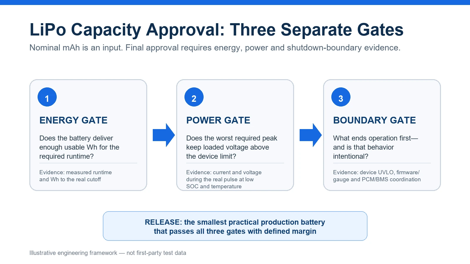
Calculate the device’s charge or energy requirement from the complete operating duty cycle—not from one convenient current value. Convert that requirement into a candidate nominal capacity using project-specific usable-capacity, temperature and end-of-life evidence. Then check peak-loaded voltage and confirm which device, firmware or protection boundary ends runtime. A LiPo capacity decision is complete only when the production-intent battery passes all three checks in the final device.
Need an initial estimate first? Use THOR Power’s battery runtime and required-capacity calculators, then return to this guide to turn the estimate into a testable OEM requirement.
The Real Problem: 100 mA for 10 Hours Does Not Automatically Approve 1,000 mAh
A product team measures about 100 mA and needs 10 hours of runtime. Multiplying current by time gives 1,000 mAh, which is useful for a first screen. It is not yet a battery specification.
Real products sleep, wake, transmit, drive displays or motors and pass power through converters. Battery voltage changes during discharge, and operation ends at a defined system boundary. A battery can meet the label-mAh calculation and still miss runtime; a short peak can also be mistaken for continuous demand and force an oversized battery.
If runtime is short, do not immediately buy more mAh. First determine what ended operation: insufficient usable energy, peak-load voltage sag, device undervoltage shutdown, gauge or firmware logic, PCM/BMS action, temperature, incomplete charging, current-path loss or an incorrect load model. More capacity directly fixes only some of these causes.
RUNTIME MISS DIAGNOSTIC — CHECK IN THIS ORDER
1. Starting energy — Did the LiPo battery actually reach the approved full-charge condition?
2. Delivered energy — How many Wh reached the product before operation ended?
3. Peak event — Did a current pulse cause loaded-voltage collapse, reset or protection action?
4. Ending boundary — Which acted first: device UVLO, firmware/gauge logic or PCM/BMS protection?
This sequence separates an energy shortage from premature shutdown before capacity is increased.
1. Define What the Runtime Target Means
Before measuring current, define the conditions under which the runtime claim must be true. Otherwise, two teams can test the same battery and produce different but technically defensible results.
Starting condition: exact full-charge voltage, charger termination current, allowed post-charge rest time and initial state of charge. Confirm whether the design is a 4.2 V or 4.35 V lithium battery system before setting the runtime baseline.
Ending condition: device UVLO, firmware shutdown, displayed 0%, loss of a required function or another approved product boundary.
Use profile: operating states, duration, repetition rate, radios, display brightness, motors, heaters and user interactions.
Environment: required low and high operating temperature, airflow and enclosure condition.
Life point: beginning-of-life only, or the required runtime after the defined cycle/calendar-aging condition.
Production requirement: minimum guaranteed performance, not only a typical prototype result.
A supplier cannot responsibly recommend capacity from runtime alone. The same 10-hour target can require different nominal capacity when the cutoff voltage, temperature, charger, enclosure and end-of-life requirement change.
2. Measure the Real Device Load
Most compact electronics do not draw one constant current. A wireless sensor may sleep for most of its cycle, wake for processing and transmit in short bursts. Texas Instruments notes that pulsed-load analysis must account for the time spent in all operating modes; optimizing only the heavy-load event can miss the energy consumed by long low-power states.
Measure at the battery terminals when possible
A 100 mA measurement on a regulated 3.3 V rail is not automatically 100 mA from a LiPo cell. Converter efficiency, quiescent current and changing battery voltage alter the battery-side current. Measuring voltage and current at the battery terminals captures the complete power path and avoids guessing converter loss twice.
Use a current profiler or power analyzer for pulsed loads
A handheld multimeter may show a stable average while missing a millisecond radio burst or motor inrush. Record peak amplitude, pulse duration, repetition interval and battery voltage during the event. Sampling bandwidth must be high enough to preserve the event that could cause a reset or protection action.
If no battery is available yet
Use a programmable DC source with sufficient transient capability to sweep the intended LiPo battery-voltage range. Set the protective current limit above the expected normal load so the source does not create an artificial voltage collapse. Measure device input power at representative high, middle and low battery voltages. If battery source impedance is being emulated, define that impedance explicitly and verify that the source, leads and measurement shunt preserve the real transient behavior. After the electrical boundary is defined, use the 3.7V LiPo battery model range to shortlist candidates by capacity and size.
Iavg = Σ(Ibattery,k × tk) / Tcycle
Qideal = Iavg × target runtime = Σ(Ibattery,k × tk)
Use this path only when current is measured or modeled at the battery side.
3. Calculate the First Capacity Requirement
Choose the calculation path that matches the data actually available. Do not mix battery-side current with downstream load power in the same equation without accounting for the converter and power path.
Path A: battery-side current is known
CHARGE-BASED INITIAL SIZING
Qideal = Σ(Ibattery,k × tk)
Qnom,min ≥ Qideal / (fusable × ftemperature × fEOL)
Each factor must be supported by cell data or project testing; do not
insert universal defaults.
Preferred method: When controlled cell or final-device testing already provides a worst-condition usable-capacity fraction that includes load, cutoff, temperature and aging state, use that measured combined factor directly rather than multiplying separate derating factors.
The usable fraction represents the part of nominal charge that the final device can remove before its approved cutoff under the intended load. Temperature, aging and cutoff effects are not always independent. Apply separate factors only when the evidence shows they represent distinct losses; otherwise use a measured combined usable-capacity factor. Aging also can increase resistance, so an end-of-life Energy Gate pass does not replace a repeat Power Gate at the required low SOC and temperature. At this stage, custom LiPo battery selection is still a screening step, not a model approval.
Path B: device power is known
Ebattery,required = Σ[(Pload,k / ηk) × tk]
Approve against measured usable Wh to the real cutoff—not nominal Wh alone.
For a changing-efficiency converter, use η for each operating state or measured battery input power.
Wh is the stronger comparison when battery voltage changes materially or when comparing different voltage platforms. mAh remains useful within the same voltage class, but mAh without voltage is not an energy comparison.
If current is measured at the battery terminals, converter loss and most device-side power behavior are already included. Do not divide that battery-side result by converter efficiency again. If measurement is taken at a regulated rail, conversion loss must be included before estimating battery energy.
4. Worked Example: From 424 mAh to a Candidate Rating
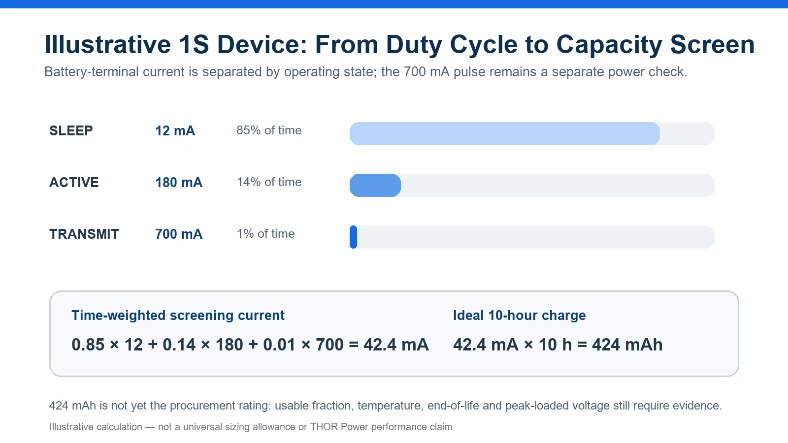
Consider an illustrative 1S wireless device with battery-terminal current measured in three operating states:
| State | Battery current | Time share |
|---|---|---|
| Sleep | 12 mA | 85% |
| Active processing | 180 mA | 14% |
| Radio transmit | 700 mA | 1% |
The time-weighted current is 0.85 × 12 + 0.14 × 180 + 0.01 × 700 = 42.4 mA. For a 10-hour target, the ideal charge requirement is 424 mAh.
Now assume—not as a universal rule, but as explicit project inputs—that final-device tests or controlled cell data show:
The device can use 85% of nominal capacity before the approved cutoff under the intended load and temperature.
The product must still meet its runtime requirement when available capacity has declined to 80% of beginning-of-life capacity.
Qnom,min ≥ 424 mAh / (0.85 × 0.80)
Qnom,min ≥ 623.5 mAh
Initial candidate direction: a cell with at least the required minimum—not merely typical—capacity.
This calculation supports a candidate range; it does not approve a specific 624 mAh or 650 mAh cell. The selected model must still fit the finished pack envelope, support the 700 mA pulse and pass runtime validation at the required temperature and life condition. If the 85% usable factor already came from an aged-cell low-temperature test, applying separate temperature and end-of-life factors would double-count the same loss. End-of-life approval must also repeat the Power Gate because resistance growth can reduce loaded-voltage margin even when remaining capacity still passes the energy calculation. For this illustrative 624–650 mAh candidate range, review medium-capacity LiPo batteries only after the electrical and mechanical limits are defined.
MINIMUM VS TYPICAL CAPACITY
A LiPo cell advertised as “650 mAh” is not automatically acceptable. If the supplier specifies 650 mAh typical but only 620 mAh minimum, it does not satisfy a 623.5 mAh minimum-capacity requirement.
Procurement release should therefore tie the requirement to minimum guaranteed capacity and the exact charge, discharge, cutoff and temperature conditions used for that rating.
5. Check Peak Current and Loaded-Voltage Margin
Capacity mainly supports operating time. The worst required current event determines whether the battery and current path can maintain sufficient loaded voltage. A low-average-current device can still reset during a radio burst, motor start, heater event or flash pulse.
Vloaded ≈ VOCV − Ipeak × Rtotal
Rtotal = cell + PCM FETs + tabs/welds + wire + connector + PCB path
Use the real pulse waveform for approval; this relationship is a diagnostic screen.
Record peak current and battery/device voltage together at the required low state of charge and temperature. Also define pulse duration and repetition. A current rating without duration can be meaningless: a cell may tolerate a short event that it cannot support continuously or repeatedly without excessive heat or voltage loss.
Confirm the exact cell’s pulse and continuous-discharge capability under its datasheet conditions.
Confirm PCM/BMS overcurrent delay and threshold tolerances do not conflict with the normal load pulse.
Measure voltage on both sides of the connector or protection path when diagnosing unexpected shutdown.
Repeat the check with production-intent wire length, connector, welds and enclosure temperature.
6. Identify the Boundary That Ends Runtime
Runtime ends when the first required product function becomes unacceptable—not when every nominal milliamp-hour has left the cell. The active boundary may be device UVLO, a firmware or gauge empty point, loaded-voltage loss, or protection action.
Texas Instruments fuel-gauge guidance illustrates the system dependency: Design Capacity is a nominal starting value, while Terminate Voltage should reflect the minimum operating voltage of the actual system. Gauge configuration is device- and gauge-specific, but the broader lesson is that available runtime depends on the product boundary, not the capacity label alone.
Source: Texas Instruments, Quickstart Guide for bq27441-G1 (SLUUAP7)
PROTECTION COORDINATION
In architectures where the PCM/BMS is intended as a protective backstop, routine product shutdown should normally occur at a controlled device or firmware boundary above the protection threshold, with enough margin for load transients and component tolerances. Use the PCM/BMS selection guide to align normal shutdown and protection behavior.
If the approved architecture intentionally uses protection action as part of normal operation, that behavior, recovery logic and lifetime impact must be validated explicitly rather than assumed.
7. Select a Candidate Cell and the Evidence Behind Its Rating
Ask for more than a model number and headline capacity. A useful supplier response ties the rating to the exact cell or finished pack, its characterization condition and the intended production configuration. Candidate selection may begin from a standard model or a custom configuration, but approval remains tied to the exact finished battery.
| Evidence to request | Why it matters |
|---|---|
| Exact cell/pack model and revision | Prevents unapproved substitution after prototype testing. |
| Minimum and typical capacity | Production approval should not rely only on a typical value. |
| Charge voltage, taper current, discharge rate and cutoff used for rating | Shows whether the published capacity condition matches the product. |
| Discharge curves at relevant load and temperature | Reveals voltage plateau, early cutoff and usable-energy changes. |
| DC resistance or pulse data with test method | Supports loaded-voltage screening; AC impedance alone does not prove pulse behavior. |
| Continuous and pulse-current limits | Must include pulse duration, repetition and temperature conditions. |
| Finished-pack drawing | Capacity, PCM, wire, connector, insulation and pouch tolerances must fit the product. |
| Protection and charger coordination | Confirms voltage/current thresholds and normal-versus-protective shutdown behavior. |
Before release, compare the controlled finished-pack drawing with the product cavity and keep-outs; nominal cell dimensions alone are not enough.
IEC 61960-3 provides performance-test and marking criteria within its published scope, but a standard reference does not replace the exact supplier datasheet and final-device test. Use the applicable product, transport and market standards separately from the runtime calculation.
8. Validate Runtime in the Final Device
Release the production-intent configuration, not a spreadsheet. The final test must connect the load model, usable energy, peak-loaded voltage, cutoff behavior, temperature, life target and mechanical assembly. Plan the sequence using the battery-pack prototype testing and validation guide.
| Validation area | Minimum approval evidence |
|---|---|
| Starting condition | Approved charger, full-charge voltage, termination behavior, rest time and initial SOC are controlled. |
| Duty cycle | Firmware and device activity reproduce the required real-use profile. |
| Usable runtime | Elapsed time and delivered Wh are recorded to the approved product boundary. |
| Peak margin | No unintended reset or protection action during the defined event at low SOC and required temperature. |
| Boundary | Device UVLO, gauge/firmware and protection states are logged so the first endpoint is known. |
| Life and production | The required aged condition and minimum-capacity expectation remain compliant. |
| Mechanical configuration | Exact cell, PCM, wire, connector, insulation and enclosure match production intent. |
For debugging, log battery current, battery voltage, device rail voltage, shutdown reason and relevant gauge/protection flags on the same time base. A simple elapsed-time result can prove failure but may not reveal the cause.
The correct battery is not the highest-mAh cell that fits. It is the smallest practical production battery that reliably passes the energy gate, power gate and intended shutdown boundary with the defined project margin.
Turn the Calculation Into a Candidate Battery
Share the device load, peak event, cutoff, temperature and finished-size limits for an engineering review.
9. What the Buyer Should Send—and What the Supplier Should Return
| Buyer should send | Supplier should return |
|---|---|
| Target runtime plus beginning/end-of-life requirement | Candidate model, minimum/typical capacity and expected usable-energy validation plan. |
| Operating states and duty cycle | A traceable interpretation of the energy model and any assumptions. |
| Battery-side current/power log | Expected runtime test condition from approved full charge to the real cutoff. |
| Peak current, duration and repetition | Loaded-voltage or pulse-validation condition at defined SOC and temperature. |
| Device UVLO and firmware/gauge criteria | Expected first shutdown boundary and protection coordination. |
| Charger voltage, taper behavior and power path | Confirmed charging condition and compatible cell voltage class. |
| Temperature range and required life point | Applicable derating or verification evidence without arbitrary margin. |
| Maximum finished battery dimensions and drawing | Finished pack drawing including PCM, wire, connector and tolerances. |
If detailed logs are not yet available, send at least: target runtime, measured average battery current or power, peak current with duration, device cutoff voltage, operating temperature and maximum finished battery dimensions. State clearly where and how the current was measured.
Key Takeaways
Define the approved full-charge condition, ending boundary, temperature and life point before calculating capacity.
Use the complete LiPo battery-side duty cycle for energy sizing; treat peak current as a separate Power Gate and avoid counting converter loss twice.
Convert ideal mAh or Wh into a candidate rating only with project-specific usable-capacity evidence, and release against minimum guaranteed capacity rather than a typical label value.
Repeat the loaded-voltage check at low SOC, required temperature and end-of-life condition using the production-intent PCM, wire, connector and enclosure.
Release measured usable runtime and a known shutdown boundary in the finished LiPo configuration—not nominal mAh alone.
FAQ: LiPo Battery Capacity for Device Runtime
How do I calculate what mAh LiPo battery my device needs?
Calculate charge from the complete battery-side duty cycle: Qideal = Σ(Ibattery,k × tk). Then convert that result into a candidate nominal capacity using project-specific usable-capacity, temperature and end-of-life evidence. Finally, verify the peak-loaded voltage and real device cutoff before approval.
Is a 1,000 mAh battery guaranteed to run a 100 mA device for 10 hours?
No. The calculation is an ideal first screen. Real runtime also depends on load variation, charging condition, device cutoff, converter behavior, temperature, cell resistance, production capacity, aging and the current path.
Should I size LiPo capacity from average current or peak current?
Use the complete duty cycle or battery-side average energy for the capacity screen. Check peak current separately to confirm that the exact battery, PCM, wire and connector can maintain sufficient loaded voltage without excessive heat or protection action.
When should I use Wh instead of mAh?
Use Wh when battery voltage changes materially during operation or when comparing different voltage platforms. mAh can be useful within the same voltage class, but it does not describe energy without voltage.
Why can a battery still contain charge when my product shuts down?
The loaded voltage may cross the device, firmware, gauge or protection boundary before all nominal charge is removed. Low SOC, current pulses, resistance, temperature and current-path loss can reduce usable voltage margin.
How much extra LiPo capacity margin should I add?
There is no universal percentage. Define what the margin must cover—such as minimum production capacity, low temperature, end-of-life performance or cutoff reserve—and support each factor with supplier data or project testing. Avoid counting the same loss twice.
Can I rely on PCM/BMS undervoltage cutoff as the normal empty point?
If the PCM/BMS is intended as a protective backstop, the device should normally shut down at a controlled UVLO or firmware boundary above the protection threshold. Confirm the intended coordination, threshold tolerances, recovery behavior and peak-loaded-voltage margin for the exact LiPo design.
What should I send a battery supplier for a capacity recommendation?
Send the runtime target, operating duty cycle, battery-side current or power, peak current with duration and repetition, device cutoff, charger condition, temperature range, life requirement and maximum finished battery dimensions.
Conclusion
A defensible LiPo capacity decision begins with the real duty cycle, not the largest or smallest current in a specification. Calculate the initial charge or energy requirement, translate it into a candidate rating with explicit project evidence, keep peak power as a separate check and identify the boundary that actually ends operation.
This workflow prevents an undersized battery that misses runtime and an oversized battery selected because a short pulse, early cutoff or measurement error was mistaken for insufficient capacity.
Planning a Runtime-Constrained LiPo Product?
Share the target runtime, battery-side load profile, peak current and duration, device cutoff, charger, temperature range and finished-size limits.
Technical References
- Texas Instruments — Selecting a DC/DC Converter for Maximum Battery Life in Pulsed-Load Applications, SLVA740A, revised July 2021.
- Texas Instruments — Quickstart Guide for bq27441-G1, SLUUAP7.
- IEC 61960-3:2017 — Secondary lithium cells and batteries for portable applications.
Evidence standard: Published specifications must remain tied to the exact source and test condition. Numerical examples and diagrams in this article are illustrative engineering screens, not universal battery-sizing allowances or THOR Power first-party performance claims. Final selection must use the exact cell/pack documentation and measurements from the intended device, charger, duty cycle, temperature range and production configuration.



Dr. Maximilian Weber is THOR Power's Chief Scientist and a senior expert in lithium battery technology. His technical review focuses on battery safety, performance optimization, energy density and custom battery solution development.
Last technical review: September 2026

Victor Xiong holds a Master's degree from The Chinese University of Hong Kong, Shenzhen. He leads THOR Power's OEM Division and focuses on custom battery solutions for global device brands, product developers and industrial customers.