Custom Solutions
Connector, Wire & PCM/BMS Customization
THOR Power engineers custom battery PCM/BMS, connector, and wire layouts matched to your exact product — protecting how each pack fits, charges, and performs, verified on samples before mass production.
What we customize
Three things that make a battery fit your product
Most custom battery problems come down to the interface — not the cell. These are the three areas we tune for every project.
For pouch-cell projects, these connector, wire and protection choices can be specified as part of a custom LiPo battery configuration.
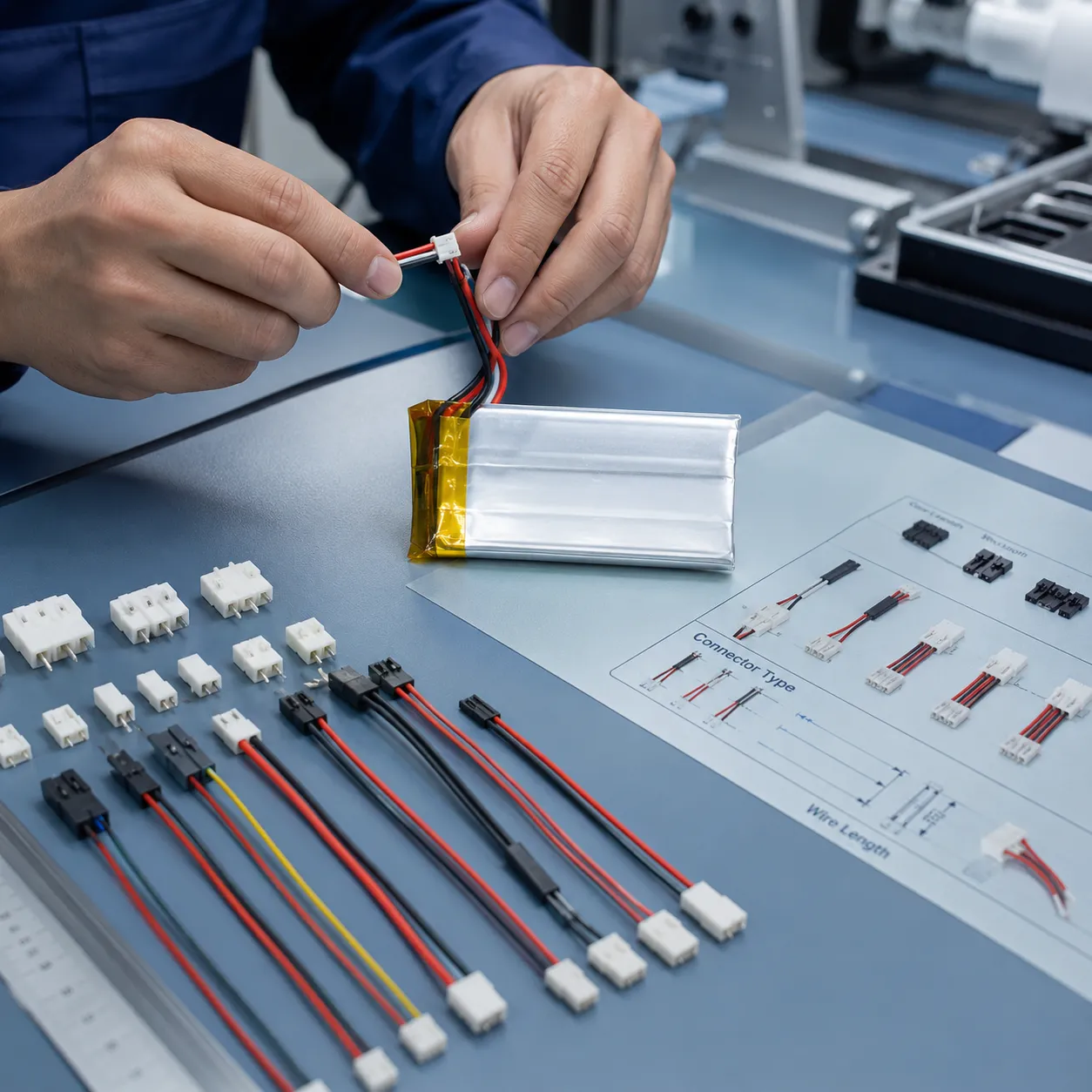
01 · Connector
The right connector
JST, Molex, or a custom terminal — matched to your board, current, mating cycles, and available space.
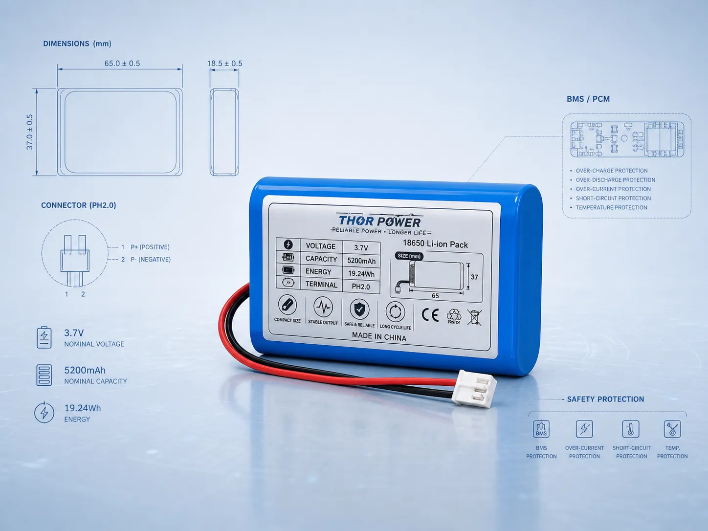
02 · Wire
Wire built to layout
Gauge, length, polarity, and exit direction set so the pack drops into your enclosure without strain or rework.
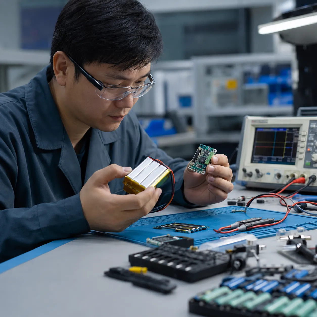
03 · Protection
PCM / BMS protection
Over-charge, over-discharge, over-current, and short-circuit protection — sized to your voltage and cell count.
Connector
Connector options we work with every day
Send us a part number, a photo, or your mating connector — we'll confirm fit and polarity before sampling. Common families below.
| Connector | Typical use | Notes |
|---|---|---|
| JST SH (1.0mm) | Ultra-compact wearables, IoT, sensors | Smallest pitch; for low current and tight space |
| JST PH (2.0mm) | 3C devices, small LiPo packs | The most common LiPo connector |
| JST XH (2.5mm) | Larger packs, balance leads | Higher current; common for multi-cell balancing |
| Molex | Industrial & medical devices | Many series — specify the exact one or send a sample |
| Bare tinned leads | Solder-to-board or in-house assembly | No connector; strip length and tinning to spec |
| Custom terminal | Non-standard or proprietary interfaces | Share a drawing or sample and we'll source or tool it |
Wire
Wire that matches your layout, not the other way around
Wire that's too thin overheats; too thick won't route. Too long adds resistance and clutter; too short forces strain on the joints. We set every detail to your enclosure.
- Gauge (AWG) chosen for working current and flexibility
- Length measured from cell tab to connector for your layout
- Polarity & color marked clearly to avoid assembly errors
- Exit direction and routing to fit your housing
- Insulation & sleeving for abrasion and temperature needs

Protection
PCM or BMS — which protection your pack needs
Both protect the cell. The difference is cell count and whether you need balancing. Not sure which applies? We'll advise from your voltage and capacity.
PCM
Protection Circuit Module — single-cell & low-cell packs
- Over-charge protection
- Over-discharge protection
- Over-current & short-circuit protection
- Compact — fits thin LiPo and small packs
- Best for 1S and simple low-cell designs
BMS
Battery Management System — multi-cell packs
- All PCM protections, plus:
- Cell balancing across the series string
- Temperature monitoring options
- Optional fuel-gauge / communication (per project)
- Best for 2S and above — 18650 / 21700 / Li-ion packs
How it works
From your spec to a verified sample
STEP 01
Send requirements
Connector, wire, protection, voltage, capacity, and application — or use the builder below.
STEP 02
Engineering review
We confirm fit, polarity, current, and the right PCM/BMS before anything is built.
STEP 03
Sample & verify
A sample confirms connector position, charging, and assembly fit. No MOQ for samples.
STEP 04
Production supply
After sign-off we follow QC, documents (UN38.3 / MSDS), and stable long-term supply.
Spec Builder
Configure your connector, wire & protection
Pick the options that match your product. We build a clean spec summary as you go — copy it, or send it straight to our engineers for a fast, accurate quote.
Questions Engineers Ask About Connectors, Wires and PCM/BMS
Connector fit, wire routing, polarity, and protection-circuit behavior affect how a battery pack performs inside your device. These answers address the most common engineering and sourcing questions.
How do you confirm that a connector will fit and mate correctly?
We start from your mating connector, board header, or an existing battery you want to match. If you can provide a part number, photo, drawing, or physical sample, we confirm pitch, pin count, polarity, keying, and mating force before building any sample. If only a device photo is available, we identify the most likely connector family and confirm it with you before proceeding.
What determines the correct wire gauge and length for a battery pack?
Wire gauge selection should account for continuous current, peak current and pulse duration, wire length and the resulting conductor resistance, allowable voltage drop under load, temperature rise at the expected operating conditions, connector current rating, and available installation space. If device current or peak current increases from the original specification, the existing wire gauge should not automatically be assumed suitable — it should be recalculated and revalidated against the updated electrical and thermal requirements. Wire length is measured along the actual routing path from the cell tab to the connector inside the enclosure, because longer wire increases resistance and voltage drop under the same load.
What is the difference between a PCM and a BMS, and how do you decide which one to use?
A PCM (Protection Circuit Module) provides over-charge, over-discharge, over-current and short-circuit protection for single-cell and simple low-cell configurations. A BMS (Battery Management System) adds cell balancing and optional temperature monitoring or communication for multi-cell series packs. The choice depends on cell count, series-parallel structure, and whether the application requires active balancing. For 1S LiPo packs, a PCM is standard. For 2S and above, or 18650/21700 packs, a BMS is typically required.
Can you match a specific connector polarity and wire color scheme?
Yes. Polarity, wire color, pin assignment, and exit direction are set to your specification. If you are replacing an existing battery, send the original or a clear photo showing pin orientation and wire colors. We reproduce the exact polarity and color scheme so the new pack is a direct drop-in replacement with no risk of reverse connection.
How do PCM/BMS protection thresholds get set for my application?
Protection thresholds are confirmed from the selected cell specification, charger, and real device load profile. Parameters include overcharge voltage, over-discharge cutoff, continuous overcurrent limit, short-circuit response time, and — for BMS — cell-balance start voltage. These values must match your actual load and charger behavior rather than using generic defaults, because a threshold that is too tight causes nuisance shutdowns and one that is too loose fails to protect the cell.
Can PCM/BMS protection cause a device to shut down during startup or peak load?
Yes. If the overcurrent threshold is set below the device startup surge or peak pulse current, the protection circuit will trip and cut power. This is one of the most common field issues with protected battery packs. During engineering review, we check pulse current requirements including startup current, pulse amplitude, pulse duration and repetition frequency to make sure the protection threshold has enough headroom for the real load profile without compromising cell safety.
Can you reproduce an existing battery connector and wire harness?
Yes. Send the existing battery, a photo with dimensions, or a drawing showing connector type, pin count, wire gauge, wire length, color, polarity and exit direction. We reverse-engineer the interface and build a sample that matches the original connection. After you verify fit and function on a sample before mass production, we lock the specification for stable long-term supply.
Does my LiPo battery need an NTC, and how should the NTC circuit be connected?
An NTC thermistor may be required when the host device or charger needs real-time battery temperature feedback for charge control, thermal protection, or safety monitoring. The NTC can be wired in a 2-wire or 3-wire architecture, and these are not interchangeable — in some designs the NTC may share Battery− internally, while in others it uses a dedicated return conductor. The resistance value, B-constant, and connection topology must match what the host electronics expect. Temperature-based protection may be handled by the host system, the PCM or BMS, the charger, or a combination of these, depending on the overall system design. The correct approach should be confirmed during the custom battery project process before samples are built.
Have a Connector, Wire or Protection Question?
Send your connector type, wire layout, protection needs, or an existing battery sample. We review a practical, sample-verified solution matched to your device.