
Custom Battery Pack Design & Development for Non-Standard OEM Projects
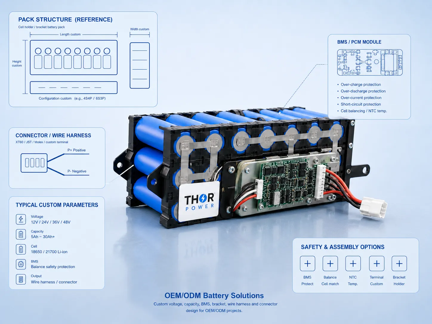
THOR Power provides custom battery pack design, engineering review, sample development, and production support for OEM/ODM projects that require non-standard battery configurations. When a standard battery does not fit the device — because of voltage, current draw, physical space, charger compatibility, or protection requirements — the project needs engineering evaluation before sampling. We work across multiple cell formats and chemistries, including LiPo pouch cells, cylindrical cells (18650, 21700), and LiFePO4.
New Device Projects
Battery Replacement
System Integration
Long-Term Supply
What Makes a Custom Battery Pack Design Work in Your Device
A custom battery pack design is not defined only by voltage and capacity. Before a sample can be built, the battery's electrical behavior must match the device's charger, load profile, and protection requirements. The finished pack must fit mechanically, survive the operating environment, and be reproducible in production. THOR Power reviews these engineering factors before recommending a battery configuration.
Engineering Review Before Sample Development
Non-standard battery pack projects may use LiPo pouch cells, cylindrical cells (18650, 21700 — available in NMC, LFP, and other chemistries), or prismatic LiFePO4 cells — depending on space, voltage, current, cycle life, and application requirements. The engineering review covers electrical design, protection logic, mechanical integration, and production feasibility before any sample is produced.
Electrical Design & Charging Compatibility
Cell chemistry determines the operating voltage range. Series configuration sets the pack voltage; parallel configuration primarily affects capacity and available current capability. Before selecting a cell, the charger's maximum voltage, charging current, and termination method must be verified against the cell's safe operating limits. A familiar nominal voltage does not guarantee that the existing charger will charge a different cell chemistry correctly.
Current Requirements: Continuous, Peak, and System Limits
Current requirements must distinguish continuous operating current from startup or transient peak current. Peak duration, repetition frequency, and recovery time determine whether the cell can sustain the load safely. The BMS overcurrent threshold must accommodate real peak demand — if set too low, the pack shuts down during normal device operation. Cell capability, MOSFET ratings, wiring, and connector ratings all affect actual current-handling capacity.
BMS, NTC, and Protection Configuration
Protection thresholds — overcharge, over-discharge, overcurrent, short circuit — must match the cell specification and actual device behavior. For multi-cell series packs, cell-voltage monitoring and balancing needs should be evaluated based on configuration and expected variation. NTC sensors provide temperature data; whether protection is executed by the battery circuit or device controller must be confirmed. Battery-side and device-side protection should be reviewed together to prevent conflicts.
Mechanical Integration & Finished-Pack Dimensions
The finished battery pack typically has a larger installation envelope than the bare cell. PCM/BMS board placement, wire routing, connector orientation, insulation, and protective packaging contribute to the overall dimensions. Manufacturing tolerances, assembly clearance, and applicable cell swelling allowances over the intended service life should be accounted for when designing the device enclosure. For LiPo-specific considerations, see Custom LiPo Battery Packs. For cylindrical cell options, see 18650/21700 Battery Packs.
Not Sure Which Battery Solution Fits Your Project?
Explore how our engineering team reviews custom battery requirements, evaluates design feasibility, and supports OEM/ODM development.
OEM/ODM Battery Projects We Support
Different projects face different engineering challenges. A new device may not have finalized its power requirements. A replacement project must match an existing interface without the original supplier’s documentation. A private-label project needs consistent branding and packaging across repeat orders. THOR Power helps identify the technical risks before sample development begins.
New Device Battery Development
THOR Power reviews available device space, working current and peak current, charging method, protection requirements, and assembly constraints before recommending a cell format and pack configuration. This reduces the risk of selecting a battery that fits physically but fails electrically — or one that works in testing but cannot be reproduced consistently in production.
Battery Replacement & Upgrade
THOR Power can review the original battery’s dimensions, voltage, capacity, connector, wire layout, polarity, and protection configuration to recommend a compatible replacement or upgrade. Where the original documentation is incomplete, sample testing against the actual device helps confirm electrical and mechanical compatibility before committing to production.
Private Label Battery Supply
THOR Power supports OEM label design, specification documentation, packing consistency, and repeat-order production control for branded battery supply projects. After the initial engineering review and sample approval, the confirmed specification is locked so subsequent batches match the approved sample.
Not sure which battery application fits your project?
Explore THOR Power application pages to compare small electronic device batteries, power tool battery packs, and energy storage & backup power batteries.
OEM/ODM Battery Development Process
Each stage of a custom battery project involves engineering decisions that affect the final product. This overview highlights what must be evaluated at each step. For the detailed project workflow — including timelines, deliverables, and approval gates — see How Custom Battery Projects Work.
Requirement Review
Confirm device space, target voltage, capacity range, working current, peak current, charging method, operating temperature, and application environment. Identify whether the project needs a standard cell with custom packaging or a fully non-standard configuration.
Battery Solution Proposal
Recommend cell chemistry, series/parallel configuration, protection circuit type, connector layout, and pack structure. Verify that the proposed design is compatible with the device’s charger and load requirements before proceeding to sample production.
Sample Development
Produce engineering samples with confirmed dimensions, connector, wire routing, protection board, and labeling. The sample should represent the production configuration — not a simplified prototype that will need redesign later.
Device Testing & Validation
Test samples under real device operating conditions — not bench voltage checks alone. Evaluate charging behavior, continuous and peak load performance, temperature rise, runtime, mechanical fit, and BMS protection response. Adjust configuration if needed before approval.
Specification Lock & Production Preparation
After validation, freeze the specification: BOM, dimensions, protection parameters, connector, labeling, packaging, and inspection criteria. A validated sample is not automatically approved for mass production — the transition requires explicit specification lock and production readiness confirmation.
Production & Long-Term Supply
During production, batch consistency is maintained through cell matching, assembly inspection, electrical testing, and packaging control. Quality records and shipping documents (UN38.3, MSDS where applicable) are prepared according to order requirements.
A structured development process reduces the risk of wrong battery selection, sample-to-production deviation, and long-term supply problems. For the complete project workflow with detailed stage descriptions, see How Custom Battery Projects Work.
Quality Control from Engineering Validation to Production Shipment
Quality control for a custom battery pack covers the full path from engineering validation to production shipment. It begins during the design review — verifying that the proposed configuration meets the device’s electrical and mechanical requirements — and continues through production with cell-level, assembly-level, and pack-level checks. The specific QC scope depends on the project’s configuration and requirements.
Full Production Chain Quality Control
For custom battery projects, each key process is reviewed to reduce batch inconsistency, connector mismatch, electrical performance issues, packing errors, and long-term supply risks.
Documents & Shipping Support
Shipping and compliance documents are prepared according to the battery model, pack configuration, energy rating, and transportation method. Document availability depends on the specific product and configuration.
- UN38.3 Test Summary (configuration-dependent)
- Battery Specification Sheet
- Product Label & Safety Markings
- MSDS / SDS (where applicable)
- Packing Information & Carton Marks
- Shipping Document Support
Note: UN38.3 is a transportation safety test required for shipping lithium batteries — it applies to the specific pack configuration, not only to the bare cell. IEC 62133-2 is a safety standard for lithium-ion and lithium-polymer cells and batteries used in portable equipment. UL certification (such as UL 2054 or UL 62133) covers product safety and may be required for certain product categories in North America. CE marking indicates conformity with applicable EU legislation; for batteries placed on the EU market, Regulation (EU) 2023/1542 introduces requirements covering sustainability, labeling, and end-of-life management, with obligations phased in over several years — not all provisions are in effect yet. These requirements depend on the final battery pack configuration, the device application, the battery category, and the target market — they are not automatically covered by cell-level test reports. Required certifications and test samples should be identified during project planning.
See How We Control Battery Quality
Quality control continues from sample development to long-term mass production. Watch how THOR Power manages production process control, inspection, testing, and shipment review for custom OEM/ODM battery projects.
Custom Battery Pack Engineering FAQ
These questions address the most common engineering and procurement concerns that OEM/ODM teams evaluate when planning a custom battery pack project. Each answer focuses on what should be reviewed before committing to sample development or production.
01 When does an OEM device require a custom battery pack instead of a standard product?
A standard battery — or one with minor modifications such as a different connector, wire length, or label — may work if the voltage, capacity, physical dimensions, and discharge current of an existing product already match the device. A custom battery pack design is typically needed when the device requires a non-standard voltage or series/parallel configuration, when the available space does not match any existing cell geometry, when the load profile demands specific protection settings, or when the charger imposes constraints that a standard protection circuit cannot accommodate. Providing your device specifications early allows the engineering team to recommend the most practical approach — whether that is a modified standard product or a fully custom development.
02 How can a custom battery pack be designed for specific charging-voltage limits?
Each cell chemistry has a normal full-charge voltage. When the device or charger imposes a different maximum charging voltage, the engineering review evaluates two approaches.
First, selecting a cell chemistry and series count whose standard full-charge voltage falls within the charger's operating range.
Second, where the cell manufacturer's specifications permit and charging control is adequate, operating below the normal full-charge level. This uses a partial state-of-charge range — usable capacity and runtime are reduced, and not all chemistries are suitable for sustained restricted-voltage operation.
In either case, the review covers charging current limits, termination behavior, and capacity impact. For multi-cell series configurations, cell-voltage monitoring and balancing should be evaluated to prevent any cell from exceeding its safe limit under worst-case conditions.
The charger regulates normal charging. The BMS overcharge threshold provides an independent safety layer — these are separate functions. Final compatibility must be confirmed through design review and device-level testing with the production charger, cells, and protection circuit.
03 How do you select a BMS for continuous loads and short peak-current demands?
BMS or protection circuit selection must account for the device's actual current profile — not just the nominal load. The continuous operating current, peak current amplitude, peak duration, repetition frequency, and recovery time all affect whether the protection circuit will allow normal device operation without tripping. The overcurrent threshold should accommodate real peak demand with appropriate margin. Beyond the protection IC settings, the MOSFET ratings, wiring resistance, and connector current ratings also limit the system's actual current-handling capacity. A protection circuit rated for a given current does not guarantee that the complete battery pack will deliver that current without excessive voltage sag or heat generation.
04 How is actual battery runtime evaluated under device operating conditions?
Nominal capacity is measured under controlled conditions that may not reflect actual device operation. Real-world runtime depends on the actual load profile, the device's discharge cutoff voltage, power conversion efficiency, operating temperature, and battery aging over time. The device's cutoff voltage, the cell's safe operating range, and conversion losses between the battery and the load all affect how much of the nominal capacity is usable in practice. Higher discharge currents further reduce usable capacity due to internal resistance losses. Runtime estimation should be validated on the actual device under representative conditions — THOR Power does not guarantee specific runtime or backup-time figures without supporting test data.
05 How can PCM/BMS, NTC, connectors, and wiring fit within a limited installation space?
The finished battery pack typically requires a larger installation envelope than the bare cell. The PCM or BMS board, NTC sensor, wire exit path, connector, insulation, and protective wrapping all contribute to the final dimensions. Manufacturing tolerances, assembly clearance, and applicable cell swelling allowances — particularly relevant for LiPo pouch cells over extended cycling — should be factored into the device enclosure design. The wire outlet direction, connector position, and fixing method also affect final assembly. THOR Power confirms the expected finished-pack envelope before sampling so the device housing can reserve appropriate clearance. For projects using LiPo pouch cells, see Custom LiPo Battery Packs. For cylindrical-cell configurations, see 18650/21700 Battery Packs.
06 What must be validated before an engineering sample is approved for production?
Sample validation should reproduce real device conditions — not just check voltage and capacity on a bench. Key validation points include: finished dimensions and mechanical fit in the actual device enclosure, connector and polarity verification, charging behavior with the actual charger, continuous and peak load performance, voltage sag under load, runtime under representative conditions, temperature rise during operation and charging, and protection circuit behavior including overcurrent trip and recovery. A sample that powers on a device is not automatically validated for all operating conditions or approved for mass production — the transition requires explicit specification lock and production readiness confirmation. For the recommended validation approach, see How Custom Battery Projects Work.
07 How are battery certification requirements determined for different markets and configurations?
Certification requirements depend on the final battery pack configuration, target device, and destination market.
UN38.3 is a transportation safety test for lithium batteries, applying to the specific pack configuration shipped, not only the bare cell.
IEC 62133-2 is a safety standard for portable rechargeable lithium batteries — applicability depends on the target market and regulations.
UL certification may be required for certain product categories in North America. Not all battery packs require UL — the applicable standard depends on the end product and its regulatory category.
CE marking indicates conformity with applicable EU legislation. Regulation (EU) 2023/1542 introduces requirements for sustainability, labeling, due diligence, and end-of-life management, phased in over several years — supply chain due diligence has been postponed to August 2027 by Regulation (EU) 2025/1561. A CE-marked battery requires a Declaration of Conformity; specific obligations depend on the battery category.
Cell-level certifications do not automatically cover the finished pack. Applicable requirements should be identified during project planning before production begins.
Send Your Project Details for Engineering Review
Provide your device application, battery space, voltage, capacity, load current, charger details, connector requirements, and quantity plan. THOR Power will review your project and recommend a practical battery pack solution — whether your project needs a modified standard product or a fully custom development.
Talk to a Battery Engineer