LiPo Battery Connector Types: How to Choose Pitch, Wire and Polarity

Technical reviewer: Dr. Maximilian Weber
Chief Scientist at THOR Power. Reviews battery engineering content for technical accuracy, test boundaries and production relevance.

Author: Victor Xiong
OEM Division President at THOR Power, focused on custom lithium battery development and manufacturing for device programs.
An OEM engineering guide to LiPo battery connector types, pitch, pinout, wire gauge, polarity, current path, live-contact risk and production release control.
Quick Answer
Quick Answer
Choose a LiPo battery connector by exact manufacturer/series and part numbers, circuit count, pitch, battery housing, crimp terminal, mating PCB header, orientation, pin numbering, polarity, wire gauge and length, exit direction, live/unmated condition, mating-cycle requirement and current/temperature duty. “2-pin,” “JST” or pitch alone does not identify a connector. Release polarity by pin number and a defined view, then validate the complete production-intent cell-PCM-harness-device path.
THOR Power Engineering Scope
THOR Power supports project-specific LiPo pack integration with connector housing, crimp terminal, wire gauge, wire length, polarity, exit direction, PCM/NTC and label configuration. For production, the connector and harness are released together with the finished-pack drawing and electrical load requirements; sample approval is not based on a connector photo alone.
Table of Contents
- 1. Treat the Connector as an Interface, Not a Plug Name
- 2. Why “2-Pin JST” Is Not a Complete Specification
- 3. Identify Series, Pitch and Mating Geometry Correctly
- 4. Define Pinout and Polarity Without Ambiguity
- 5. Match the Battery Housing to the PCB Mating Part
- 6. Select Wire, Terminal and Harness Length as One System
- 7. Validate Current Capability Through the Complete Path
- 8. Check Mechanical Routing and Finished-Pack Fit
- 9. Worked Example: 1.25 mm PicoBlade Battery Interface
- 10. Release the Harness for Production and Quality Control
- 11. Control Alternates and Supply Continuity
- 12. A Practical Connector Selection Workflow
- 13. What Buyers Should Send in an RFQ
- 14. FAQ: LiPo Battery Connector Types
1. Treat the Connector as an Interface, Not a Plug Name
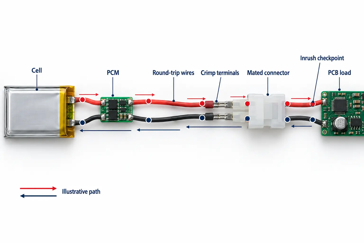
A rechargeable LiPo pack rarely ends at the pouch tabs. The electrical path normally includes cell tabs, welds, PCM or protection circuit, lead wires, crimp terminals, connector housing, mating contacts and PCB traces. The connector is therefore an electrical, mechanical and production-control interface. When the pack is active, its unmated connector may also be a live source that must resist accidental shorting and incorrect mating.
The first engineering question is not “Which connector looks right?” It is “What exact interface must this battery mate with, at what current, in what orientation, and inside what mechanical envelope?” That question forces the project to define the mating PCB part, pinout, cable routing and finished-pack geometry before production starts.
| Interface element | What must be defined | Failure if left vague |
|---|---|---|
| Battery-side housing | Manufacturer/series, exact part number or controlled drawing, circuit count, pitch, latch/polarization. | Housing may not mate even if pitch looks correct. |
| Crimp terminal | Terminal part number, compatible wire range, plating where relevant and crimp process. | Poor retention, high contact resistance or inconsistent production. |
| Mating PCB connector | Exact header/receptacle part number, vertical/right-angle, SMT/through-hole and board orientation. | Correct battery plug can still be incompatible with the device PCB. |
| Pinout/polarity | Pin 1, Pin 2, positive/negative, NTC/ID if present and defined viewing orientation. | Reverse polarity or incorrect auxiliary signal assignment. |
| Harness | Wire gauge, length, color, insulation, exit direction and strain relief. | Voltage drop, heat, interference or assembly problems. |
Interface Rule
Release the battery connector only when both sides of the interface are known. A battery-side housing without the mating PCB part, or a PCB header without the intended battery housing and terminal, is not a complete connector specification.
2. Why “2-Pin JST” Is Not a Complete Specification
“JST” is a manufacturer name, not one connector family. JST alone offers multiple wire-to-board series with different pitches, housings, locks, terminal ranges and board headers. Aftermarket listings make the problem worse because informal names such as “JST 1.25” or “micro JST” are often used inconsistently.
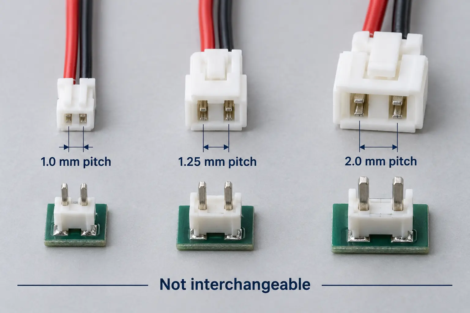
The same problem occurs with “2-pin.” Circuit count tells you only how many electrical positions exist. Two connectors can both be 2-pin and still differ in pitch, housing shape, latch geometry, polarization, mating depth and terminal design. A photograph may also reverse left and right depending on whether it shows the mating face or wire-entry face.
| Incomplete request | Why it is ambiguous | Production-safe replacement |
|---|---|---|
| “2-pin JST” | Many JST series and many non-JST copies have two circuits. | State series/part number plus the mating part. |
| “1.25 mm connector” | Pitch alone does not define family, lock or housing geometry. | State manufacturer/series, housing and PCB header. |
| “Red left, black right” | Left/right changes with viewing direction and connector orientation. | Define Pin 1 / Pin 2 polarity from a controlled view. |
| “Same as the photo” | Photos distort scale and may not show latch, key or contact position. | Use a dimensioned drawing or verified part numbers. |
| “Rated for 1 A” | Component rating depends on exact part, wire, temperature and test basis; pack limits may be lower. | Validate the complete cell-PCM-harness-device path. |
3. Identify Series, Pitch and Mating Geometry Correctly
Pitch is the center-to-center spacing between adjacent contacts. Do not measure the outside width of the plastic housing and call that the pitch. For an unknown multi-position connector, an approximate screen is: pitch ≈ center-to-center span from the first to last contact ÷ number of contact intervals. Final identification should still use the manufacturer drawing.
Official manufacturer data show why series identification matters. JST PH is a 2.0 mm-pitch wire-to-board family; JST SH is a 1.0 mm-pitch wire-to-board family. Molex PicoBlade is a 1.25 mm-pitch family with several wire-to-board and wire-to-wire configurations. These are different mechanical systems, not interchangeable names for a “small battery connector.” Treat every family-level value as a screen and verify the exact housing, terminal and mating header revision before release.
| Example family | Official pitch | Typical architecture | Published component reference | Engineering use |
|---|---|---|---|---|
| JST PH | 2.0 mm | Wire-to-board; through-hole or SMT; side/top entry. | 2 A AC/DC with AWG #24 in JST series specification. | Useful family screen; exact part and pack conditions still control. |
| JST SH | 1.0 mm | Compact wire-to-board; SMT; side/top entry. | 1 A AC/DC with AWG #28 in JST series specification. | Useful for very compact interfaces; verify wire and mechanical handling. |
| Molex PicoBlade | 1.25 mm | Wire-to-board / wire-to-wire; straight or right-angle options. | Example 53048-0210 header: 1 A max/contact and 30 mating cycles on the current Molex page; exact terminal/wire data must be checked separately. | Use only as a documented interface example; verify exact part lifecycle, availability, wire/terminal pair and project duty. |
Manufacturer component ratings are reference data for the cited series or part under the stated conditions. They are not THOR pack-level current guarantees and do not replace cell, PCM, wire, connector, temperature and device validation. The families shown are examples for compact OEM battery interfaces, not a completeness ranking or a claim that one series is generally preferred.
What to Photograph When the Part Number Is Unknown
Ask for at least three clear views: the mating face, the wire-entry face and a side view showing the latch or key. Include a scale or caliper reading, circuit count, wire diameter, PCB connector photo and any molded marking. A single front photo is often insufficient because two housings can look similar while using different latch geometry or terminal positions.
Identification Gate
Do not approve a substitute because the pitch and number of pins match. Confirm mating engagement, latch/polarization, contact position, terminal compatibility and insertion orientation against the actual PCB connector or controlled drawing.
4. Define Pinout and Polarity Without Ambiguity
Polarity errors are among the most preventable battery-integration failures. The root cause is often not an incorrect wire color; it is an unclear definition of which side of the connector is being viewed. A two-pin connector viewed from the mating face has the opposite left-right appearance when viewed from the wire-entry side.
The production drawing should define pin numbers using the connector manufacturer’s reference orientation or a clearly labeled project drawing. A useful notation is: “View: battery-side housing, mating face toward viewer, latch up. Pin 1 = Positive (+); Pin 2 = Negative (-).” If the project uses a different view, state it explicitly. For three or more circuits, identify every power, NTC, ID, data or sense position and define the device response to an open, shorted or mis-mated auxiliary pin where relevant.
| Polarity record | Acceptable? | Reason |
|---|---|---|
| Red = +, black = – | Not sufficient alone | Wire colors can be changed, crossed during assembly or interpreted from the wrong connector view. |
| Left = +, right = – | No | Left/right is view-dependent. |
| Pin 1 = +, Pin 2 = – on identified manufacturer drawing | Yes | Pin numbering survives orientation changes when tied to the drawing. |
| Pin 1 / Pin 2 + mating-face sketch + wire colors | Best practice | Combines electrical definition with production-friendly visual control. |
Polarity Red Line
If a wire-color instruction and a pin-number drawing disagree, stop the build and resolve the pin assignment before crimping or shipment. Do not “choose the more likely” interpretation. The final release should state Pin 1 and Pin 2 polarity explicitly.

5. Match the Battery Housing to the PCB Mating Part
A battery connector is only half of a mated pair. The device-side PCB part determines pitch, contact position, insertion direction, latch engagement, mated height and board access. Right-angle and vertical headers can use the same family but create very different cable routing and enclosure requirements.
For example, Molex identifies 51021-0200 as a 2-circuit, 1.25 mm-pitch PicoBlade receptacle housing and 53048-0210 as a 2-circuit, 1.25 mm-pitch right-angle through-hole PCB header. Molex currently displays only limited online information for these example parts, so a project using them must confirm lifecycle, sourcing status, approved terminal and drawing revision before BOM release. The engineering lesson is the documented mated interface, not a blanket recommendation for these part numbers.
If a customer provides only the PCB header part number, the battery supplier should identify the correct mating housing and terminal from the manufacturer documentation rather than substituting a visually similar connector. Conversely, if the customer provides only the battery plug, the mating PCB connector should be confirmed before the device layout is frozen.
| PCB-side question | Why it matters |
|---|---|
| Exact mating part number? | Confirms family, pitch, polarization and interface geometry. |
| Vertical or right-angle? | Changes wire exit, bend radius and required clearance. |
| SMT or through-hole? | Affects board construction and the available device-side geometry. |
| Where is Pin 1 on the PCB drawing? | Prevents mirror-image polarity mistakes. |
| Is insertion/removal accessible after assembly? | A connector that technically mates may still be impossible to assemble or service. |
| Does the enclosure load the connector or cable? | Side load can create intermittent contact, damaged housing or wire fatigue. |
6. Select Wire, Terminal and Harness Length as One System
The connector housing does not determine the wire automatically. Crimp terminals are designed for specific conductor and insulation ranges, and a wire that is electrically attractive may be mechanically incompatible with the terminal. The selected wire must satisfy current, voltage-drop, flexibility, routing, crimp and temperature requirements at the same time.
Harness length also matters. The cell may have adequate pulse capability, but resistance in the PCM, welds, both current-carrying conductors, crimp interfaces and mated contacts reduces the voltage delivered to the PCB. For a first-pass screen:
ΔVinterconnect ≈ I × RinterconnectPinterconnect ≈ I² × Rinterconnect
Rinterconnect should represent the defined conductive path between the released battery output and the device input: the PCM conductive path where it lies inside the measurement boundary, welds, both current-carrying conductors, crimp interfaces, mated contacts and any PCB segment intentionally included in the test. Keep cell internal voltage sag separate unless the system model explicitly includes it, because cell DC resistance changes strongly with SOC, temperature and age. A catalogue contact-resistance value covers only the specified component test and does not represent the complete battery-to-device path. Use calculation to screen options, then measure loaded pack voltage and the voltage drop across the same defined interconnect endpoints during the real load.
| Harness parameter | What to control | Why |
|---|---|---|
| Wire gauge / conductor | Terminal-compatible conductor range plus electrical load requirement. | Controls resistance, crimp quality, flexibility and space. |
| Wire length | Cut length and finished exposed length or reference points. | Changes resistance, routing and connector reach. |
| Insulation OD / material | Compatible with terminal and enclosure temperature/flex needs. | Oversize insulation may not crimp or fit; undersize may lack strain support. |
| Color | Production aid only; not the sole polarity definition. | Helps assembly but cannot replace pin numbering. |
| Exit direction | Top/side relative to battery and connector latch. | Determines finished pack length/width and wire bend. |
| Strain relief / fixation | Tape, adhesive, routing or enclosure retention as applicable. | Prevents load transfer into tabs, crimps or connector contacts. |
7. Validate Current Capability Through the Complete Path
A connector’s catalogue current rating is neither the current rating of the finished battery pack nor a system-level device-interface rating. The pack’s standalone discharge limit is set by the validated cell, tab welds, PCM/protection path and pack-side harness. The current that can actually be delivered to the device through the complete interface may be lower because of crimp/contact resistance, the mating connector, device-side PCB traces, ambient temperature and duty cycle. Treat the pack limit and the device-interface limit as two related but distinct release decisions.
Continuous current and short pulse current must be treated separately. A compact connector may tolerate a short burst that does not create unacceptable heat, while the same current may be unsuitable continuously. Conversely, a PCM can trip on a pulse even when the connector remains cool. Provide amperes, pulse duration, repetition, SOC, temperature and minimum device voltage, not only C-rate or “peak current.” Review the PCM/BMS selection guide when protection thresholds or timing may limit the interface.
If the connector can be mated or unmated while the pack is active, evaluate device input capacitance, inrush, contact bounce, arcing risk and power sequencing. A connector current rating does not establish hot-plug capability. Unless the interface is specifically designed and validated for live connection, the release procedure should require the load to be off before mating or unmating.
| Evidence | What to record | Decision question |
|---|---|---|
| Continuous load | Current, duration, terminal voltage, cell/PCM/connector temperature. | Does the complete assembly remain within approved limits? |
| Pulse load | Peak amperes, pulse width, repetition, SOC, minimum terminal voltage. | Does voltage remain above device cutoff without PCM trip? |
| Low temperature | Load test at the lowest supported condition. | Does increased cell/path resistance remove voltage margin? |
| Aged condition | Resistance and load test after defined cycle/storage aging. | Is end-of-life margin still adequate? |
| Contact / harness inspection | Crimp quality, retention, mating engagement, signs of heat or fretting. | Is the interface robust enough for production and life use? |
Current-Capability Rule
Use manufacturer connector ratings only as component-screening data. Release the pack discharge limit from the exact cell, weld, PCM/protection and pack-harness validation. Then separately confirm that the complete device interface can carry the required continuous/pulse duty without unacceptable voltage drop, heat, contact damage or protection trip.
8. Check Mechanical Routing and Finished-Pack Fit
Connector selection changes the physical battery pack. A small pouch may fit the nominal cavity while the connector body, PCM high point or wire bend extends beyond the allowed envelope. This is especially important in wearables, scanners, sensors, medical devices and compact IoT products where a few millimeters can decide whether the cover closes.
Define whether the connector exits from the short side or long side of the pouch, whether the latch faces up or down in the final assembly, where the wire bends, and whether the device can accept that bend without pressing on the pouch or connector. The insertion path must also be possible during assembly.
| Mechanical item | Check before sample approval |
|---|---|
| Finished pack T × W × L | Include PCM, tape, folded tabs, label and connector/wire local maxima. |
| Wire exit direction | Confirm relative to pouch edges and device cavity. |
| Bend radius / slack | Avoid forcing a sharp bend directly at the crimp or housing. |
| Connector body clearance | Check latch, polarization features and mating/unmating access. |
| Insertion path | Confirm the plug can be inserted after adjacent parts are installed. |
| Retention and vibration | Ensure the cable cannot pull the pouch tabs, PCM or connector during use. |
For tight devices, treat the housing, latch, wire bend and strain-relief zone as part of the pack integration rather than an accessory added after cell selection. Use the guide to nominal cell size vs finished battery size when the connector or wire path controls the enclosure.
Check the Live and Service Conditions
The battery-side connector may remain energized when unplugged. Its design should limit accidental shorting, mis-mating and cable load while still allowing the intended assembly and service process. Requirements depend on the product; do not infer them from pitch alone.
| Use condition | Primary risk | Engineering check |
|---|---|---|
| Unmated live battery | Metal tools, loose conductive parts or exposed contacts create a short path. | Prefer recessed/shrouded energized contacts and verify pack short-circuit protection, storage handling and insulation. |
| Mating or unmating under power | Inrush, contact bounce or arcing can damage contacts or reset electronics. | Define load-off procedure or validate a connector/power architecture intended for live connection. |
| Service or repeated replacement | Latch wear, cable pull and limited mating durability can reduce retention. | Set cycle requirement; check manufacturer durability, retention and cable strain relief with the real enclosure. |
| Vibration or cable movement | Fretting, intermittent contact and force transferred to the pouch tabs or PCM. | Validate retention, harness fixation and contact stability using production-intent samples. |
| Humidity, contamination or temperature | Corrosion, leakage, insulation degradation or resistance growth. | Define environment and verify materials, plating, sealing and test plan for the target device. |
Need the Connector, Harness and Mating Interface Reviewed?
Send the battery-side housing, mating PCB part, pinout, load waveform, wire route and finished-space limits. THOR Power can review contact current, crimp, polarity, strain relief and mechanical clearance before production release.
9. Worked Example: 1.25 mm PicoBlade Battery Interface
Consider a compact device whose controlled PCB drawing specifies Molex PicoBlade 53048-0210. The current Molex page identifies a 2-circuit, 1.25 mm-pitch, right-angle through-hole header and lists a 1 A maximum per contact, 30 mating cycles and limited online information. The battery requirement should therefore record the exact part, drawing revision and sourcing/lifecycle decision rather than only “2-pin 1.25 mm connector.” Connector families do not assign battery positive/negative by themselves; the polarity below is an example project release and must not be interpreted as a Molex-defined Pin 1 / Pin 2 polarity standard.
| Release field | Example production record |
|---|---|
| PCB mating part | Molex PicoBlade 53048-0210, 2 circuits, 1.25 mm pitch, right-angle through-hole header. |
| Battery housing | Molex PicoBlade 51021-0200 or formally approved compatible interface after engineering validation. |
| Terminal | Exact terminal selected for the approved wire range and crimp process; record part number on drawing/BOM. |
| Polarity (example project assignment) | Example only: Pin 1 = Positive (+); Pin 2 = Negative (-), using the manufacturer/project-defined mating-face view. This assignment belongs to the project drawing; it is not a Molex polarity standard. |
| Wire | Project-specific gauge, insulation and length; record red/black or other colors as production aids. |
| Exit direction | Defined on finished pack drawing relative to pouch and latch. |
| Electrical validation | Continuous/pulse load, voltage drop, temperature and PCM behavior using the production-intent harness. |
| Lifecycle / sourcing | Verify current manufacturer status, approved source, drawing revision, availability and any authorized alternate before release. |
This documentation prevents three common failures at once: a visually similar but non-mating 1.25 mm housing, mirror-image polarity caused by viewing direction, and a wire/terminal combination that is not controlled for production.
Worked-Example Limit
The part numbers above illustrate how to document a mated interface. They do not mean PicoBlade is the correct connector for every LiPo pack. Connector selection must follow the device PCB, current, wire, environmental and mechanical requirements of the actual project.
10. Release the Harness for Production and Quality Control
A connector that works in one hand-built sample is not production-ready. Crimp height, conductor and insulation crimp condition, strip length, terminal seating, wire cut length, output polarity and contact engagement must be controlled with the terminal supplier’s approved tooling and process. The drawing and BOM identify the approved housing, terminal, wire and mating interface; the control plan defines setup verification, inspection frequency, destructive sampling where required and 100% electrical checks.
| Production control | Minimum evidence |
|---|---|
| Incoming parts | Part identity, approved supplier, housing/terminal revision and traceability where required. |
| Crimp setup | Terminal-specific applicator/tooling, strip length and crimp-height/process limits from the approved terminal documentation; first-piece approval. |
| Crimp inspection | Conductor/insulation crimp condition, strand damage, bellmouth/brush and terminal deformation per approved process. |
| Terminal retention | Contact fully seated and locked in housing; terminal retention verified by the approved inspection method. |
| Wire length / exit | Finished harness length and exit direction within drawing tolerance. |
| Polarity / continuity | 100% pinout/polarity and continuity verification using a keyed fixture or defined method; where the released pack provides an active output during test, verify output-voltage polarity. Auxiliary NTC/ID/data pins are checked where used. |
| Mating verification | Representative mating to the approved PCB-side connector; no interference or abnormal insertion. |
| Change control | Housing, terminal, wire, plating, supplier or tooling changes trigger engineering review where they can affect fit or resistance. |
| Process capability / audit | Risk-based crimp-height, pull-force or other destructive audit using the approved method; limits are terminal/tool specific, not universal. |
Production Release Rule
Do not let the connector be an uncontrolled “equivalent” line item. If a substitute changes housing geometry, terminal, plating, wire range, latch behavior, mating force or electrical resistance, review it against the released interface and validation evidence before production use.
Use battery-pack prototype testing and validation to plan production-intent electrical, mechanical, environmental and change-control evidence before volume release.

11. Control Alternates and Supply Continuity
Long-lived OEM products need sourcing continuity, but “equivalent connector” is not a sufficient alternate-part rule. An alternate can mate physically and still change crimp tooling, wire compatibility, retention, plating, resistance, temperature performance or lifecycle status. Approve alternates against a documented interface and validation matrix before they appear on the BOM.
| Alternate review item | Evidence required | Typical revalidation trigger |
|---|---|---|
| Mating form and polarization | Dimensioned drawings plus mating trial with the released PCB part. | Any housing, key, latch, contact-position or insertion-depth difference. |
| Terminal and wire system | Approved terminal, conductor/insulation range, tooling and crimp process. | Terminal, wire gauge/insulation, applicator or supplier change. |
| Materials and plating | Contact/base material and plating specification tied to environment. | Plating material/thickness, resin or compliance change. |
| Electrical and thermal behavior | Voltage-drop and temperature evidence at project continuous/pulse duty. | Different contact resistance, rating basis or operating-temperature range. |
| Retention and durability | Latch/retention, mating-cycle and vibration/service evidence as applicable. | Different latch, contact spring geometry or stated durability. |
| Lifecycle and compliance | Manufacturer status, authorized source, traceability and required compliance records. | EOL/NRND notice, source change, counterfeit risk or regulatory update. |
Alternate-Part Gate
A purchasing cross-reference is a candidate, not an automatic approval. Engineering must define which drawing, process and validation evidence remains applicable before the alternate is released.
12. A Practical Connector Selection Workflow
- Identify the device-side connector. Start from the exact PCB part number or controlled drawing whenever possible.
- Confirm the mating family. Use manufacturer documentation to identify the approved battery housing and terminal.
- Define the mechanical view. Record latch/key orientation, mating direction, wire exit and available clearance.
- Release the pinout. Assign Pin 1, Pin 2 and any NTC/ID/signal pins using a defined view; then add wire colors.
- Select terminal and wire together. Use the approved terminal conductor/insulation range and project electrical requirements.
- Calculate and test the current path. Review cell, PCM, weld, wire, connector and PCB voltage/thermal margins together.
- Build production-intent samples. Use the intended housing, terminal, wire, PCM, tape, label and final exit direction.
- Validate mating, live condition and device fit. Check insertion, retention, output polarity, inrush/hot-plug assumptions, pulse voltage, heat, routing, exposed-contact risk and enclosure interference.
- Freeze drawing, BOM, approved sources and QC. Release part numbers, pinout, wire, lifecycle status, authorized alternates and change-control rules before mass production.
13. What Buyers Should Send in an RFQ
| Buyer input | What to provide | Why it matters |
|---|---|---|
| Mating connector | Exact PCB part number, drawing or clear photos of both mating and board sides. | Eliminates connector-family guesswork. |
| Pinout/polarity | Pin numbers and required + / – / NTC / ID assignments. | Prevents reversed polarity and signal mistakes. |
| Mechanical space | Maximum finished pack size, connector location, wire exit and insertion path. | Confirms the complete pack will fit and assemble. |
| Load profile | Continuous current, peak current, pulse duration/repetition and device cutoff. | Allows voltage-drop and current-path validation. |
| Harness | Wire gauge preference if fixed, required length, colors, routing and flex needs. | Controls resistance and mechanical integration. |
| Charge/protection | Charge voltage/current, PCM/BMS requirements and NTC if used. | Ensures connector/harness are integrated with the correct pack electronics. |
| Program | Prototype quantity, forecast, target market and validation schedule. | Defines sample, documentation and production-control needs. |
If the connector part number is unknown, send high-resolution photos of the mating face, wire-entry face, latch/key and PCB header with a scale, plus the device-side orientation and existing battery or connector sample when available. State whether the pack is unplugged during service, how often it is mated, and the expected temperature, vibration and contamination environment.
For a custom LiPo battery engineering review, send the connector/mating information together with the battery cavity and load profile. THOR Power can then return a production-intent pack proposal with controlled connector, wire, polarity and finished dimensions.
Key Takeaways
- “2-pin JST” and “1.25 mm connector” are not production specifications; exact series and mating parts matter.
- Pitch is only one identifier. Housing geometry, latch/polarization, terminal and board header must also match.
- Pin polarity should be released by pin number and defined viewing orientation; wire colors are secondary production aids.
- Connector current must be treated at two levels: the pack discharge limit is set by the cell, welds, PCM/protection and pack harness; the complete device-interface limit can be lower after crimps, mated contacts, PCB path, temperature and duty cycle are included.
- Wire gauge, terminal and wire length must be selected together because crimp compatibility and resistance both matter.
- Connector body and wire routing belong in the finished battery envelope, especially in compact devices.
- An energized battery-side plug should minimize exposed short-circuit risk; hot-plug use requires explicit validation.
- Production approval needs controlled part numbers, output-voltage polarity checks, crimp/process evidence, approved sources and change control.
- A visually compatible alternate is not automatically qualified; lifecycle and revalidation rules belong in the BOM release.
Conclusion
A LiPo battery connector is a small component with system-level consequences. The production question is which exact mating interface, pinout, terminal/wire system and current path can be released with the battery and device as one controlled design, and how that interface remains safe, sourceable and repeatable through production.
Start from the device-side part, identify the exact family and mating pair, define pin orientation and polarity, select the terminal and wire together, validate both the pack-side discharge path and the complete device interface, and check live-contact, routing, service and environmental conditions. Freeze part numbers, approved sources, alternates, drawings and measurable QC evidence before volume production.
THOR Power can support connector identification and project-specific pack integration when the mating interface, cavity, load profile, environment and production requirements are provided.
Need a LiPo Connector and Harness That Actually Fits?
Send the mating connector, pinout, cavity, load profile, wire length, charge/protection requirements and production quantity. THOR Power can review the connector, harness and finished-pack interface before samples are built.
14. FAQ: LiPo Battery Connector Types
What is the most common connector for a LiPo battery?
There is no universal most-common connector for OEM LiPo packs. JST PH, JST SH, Molex PicoBlade and many other families are used depending on device PCB, space, wire and current requirements. The correct connector is the one that matches the controlled mating interface and project conditions.
Is “JST 2-pin” enough information to order a battery?
No. JST has multiple series and many third-party listings use JST-like names loosely. Provide the exact series or part number, pitch, circuit count and mating PCB connector whenever possible.
How do I measure connector pitch?
Pitch is the center-to-center spacing between adjacent contacts. For a multi-position connector, the span between the first and last contact centers divided by the number of intervals can be used as a preliminary check, but final identification should use the manufacturer drawing.
Can two 1.25 mm 2-pin connectors be incompatible?
Yes. Equal pitch and circuit count do not guarantee the same housing, latch, polarization, terminal or mating depth. Identify the connector family and mating part.
How should LiPo connector polarity be specified?
Use pin numbers tied to a defined connector view or manufacturer drawing, for example Pin 1 = positive and Pin 2 = negative. Wire colors can be included, but they should not be the only polarity record.
Does connector current rating define the battery pack current?
No. A connector rating is component-level reference data. The pack’s standalone current limit comes from the validated cell, welds, PCM/protection path and pack-side harness. The current available at the device can be lower after crimp/contact resistance, the mating connector, device-side PCB path, temperature and duty cycle are included. Both limits should be released explicitly.
Does a longer battery wire matter?
It can. Longer wire adds resistance and can increase voltage drop and heat under load. The effect should be evaluated together with wire gauge, connector contacts, PCM and the device cutoff, especially for pulse loads.
What should I provide if I do not know the connector model?
Send clear photos of the mating face, wire-entry face, latch side and PCB connector with a scale or caliper measurement, plus circuit count, wire size and device orientation. If possible, send the existing battery or connector sample for identification.
Should a battery-side connector have exposed live pins?
Generally, the energized battery side should avoid easily accessible exposed conductive pins where practical. Use a polarized, shrouded/recessed interface and verify pack short-circuit protection, storage handling and the actual product safety requirements. The final choice depends on the device and connector system.
Can I connect or disconnect a LiPo battery while the device is powered?
Do not assume so. Device input capacitance can create inrush, and contact bounce can cause arcing or resets. Unless the connector and power architecture are designed and validated for live connection, require the load to be off before mating or unmating.
Should connector substitutions be allowed in mass production?
Only under controlled change review. A substitute that changes geometry, terminal, plating, wire range, contact resistance, latch behavior, durability, source or lifecycle status can affect mating, voltage drop and reliability even if it appears similar. Release authorized alternates with defined revalidation evidence.
Technical References
J.S.T. Mfg. Co., Ltd. PH Connector. 2.0 mm pitch wire-to-board series; published reference rating 2 A AC/DC with AWG 24.
J.S.T. Mfg. Co., Ltd. SH Connector. 1.0 mm pitch wire-to-board series; published reference rating 1 A AC/DC with AWG 28.
Molex PicoBlade Connectors. 1.25 mm wire-to-board and wire-to-wire family overview.
Molex 51021-0200. 2-circuit, 1.25 mm receptacle housing; current page provides limited online information.
Molex 53048-0210. 2-circuit, 1.25 mm right-angle through-hole header; current page lists 1 A maximum per contact, 30 mating cycles and limited online information.
Related Engineering Guides


Dr. Maximilian Weber is THOR Power's Chief Scientist and a senior expert in lithium battery technology. His technical review focuses on battery safety, performance optimization, energy density and custom battery solution development.
Last technical review: September 2026

Victor Xiong holds a Master's degree from The Chinese University of Hong Kong, Shenzhen. He leads THOR Power's OEM Division and focuses on custom battery solutions for global device brands, product developers and industrial customers.