Battery Runtime Calculation Guide: Ah, Wh, Load Profiles and Pack Sizing
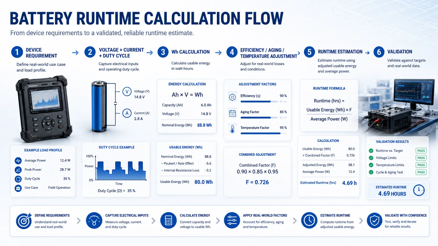
Battery runtime estimation is one of the first engineering challenges in custom battery development. This guide explains how OEM teams can translate device power requirements into usable energy, battery capacity targets and validation plans before selecting a battery architecture.
Designed for OEM engineers, product developers and sourcing teams, this article focuses on practical runtime calculation methods used during custom lithium battery development. The goal is to help teams move from a theoretical runtime target to a validated battery pack direction.

Technically Reviewed By
Chief Scientist
Dr. Maximilian Weber is THOR Power’s Chief Scientist and a senior expert in lithium battery technology. His technical review focuses on battery safety, performance optimization, energy density and custom battery solution development.
Last technical review: September 2026

Written By
President of OEM Division & Custom Battery Specialist
Victor Xiong holds a Master’s degree from The Chinese University of Hong Kong, Shenzhen. He leads THOR Power’s OEM Division and focuses on custom battery solutions for global device brands, product developers and industrial customers.
Short Answer
Battery runtime is estimated by dividing usable battery energy by average load power. For a quick estimate, use Runtime (hours) = Capacity (Wh) x usable-energy factor x system efficiency / average load (W). For current-based loads, use Runtime (hours) = Capacity (Ah) / average load current (A), then adjust for cutoff voltage, temperature, discharge rate, aging and converter losses.
Case Transparency Note
The examples in this guide are simplified engineering scenarios based on common OEM battery-sizing conversations. They are not customer-specific test reports. Final capacity, runtime, current capability, safety design and certification scope must be confirmed with the actual device, enclosure, charging method, protection circuit and validation plan.
| Formula | Use When | Important Adjustment |
|---|---|---|
| Runtime (h) = usable Wh / average W | The device load is known in watts or has multiple voltage rails. | Apply converter efficiency, cutoff voltage, aging and reserve margin. |
| Runtime (h) = Ah / average A | The load current is measured at the same battery voltage. | Do not use pack Ah directly across a different output voltage. |
| Battery energy (Wh) = nominal voltage (V) x capacity (Ah) | You need to compare different pack voltages or chemistries. | Use nominal voltage for first-pass comparison, then validate the real discharge curve. |
A calculator gives a first estimate. A production battery pack still needs cell selection, series/parallel architecture, protection design, connector and wire sizing, charger compatibility, enclosure fit, validation testing and transport documentation. For a quick first-pass estimate, start with THOR Power’s Battery Calculators, then pair the result with an OEM runtime input checklist before requesting an engineering review.
1. Battery Runtime Is a System Result, Not a Battery Label
Battery runtime looks simple on a datasheet, but in a real product it is the result of the battery, the device electronics, the discharge profile, the protection circuit, the charger strategy, the operating temperature and the end-of-discharge definition. A 10 Ah battery is not a promise that a device will run ten hours at 1 A in every application.
The label capacity is measured under a defined discharge condition. Your device may have a higher discharge current, pulse loads, sleep-mode periods, motor startup peaks, wireless-transmission bursts, DC/DC conversion losses and a cutoff voltage that stops the pack before all theoretical energy is used. That is why battery runtime calculation should be treated as an engineering estimate, not a marketing shortcut.
For OEM customers, this difference matters commercially. An over-optimistic runtime claim can cause returns, field complaints and emergency redesign. An oversized pack increases cost, weight, certification scope, tooling risk and shipping constraints. The goal is not the biggest battery. The goal is the smallest pack that meets runtime, safety, cycle life, mechanical and supply-chain requirements with a practical validation margin.
| What the Customer Often Says | What Engineering Must Clarify |
|---|---|
| We need 8 hours of runtime. | At what load profile, temperature, cutoff voltage, aging state and reserve margin? |
| The device draws 2 A. | Is that average current, peak current, startup current or current at one operating mode? |
| Can we use a 5000 mAh cell? | At which voltage, chemistry, discharge rate, enclosure limit and protection design? |
| The charger is already selected. | Does its charge voltage, current, termination and safety behavior match the proposed pack? |
2. Why a Runtime Calculator Is Only the First Step
A battery runtime calculator is useful because it forces a team to translate a loose requirement into numbers. It helps you estimate average load, usable energy, reserve margin and efficiency loss before the supplier conversation starts. But the calculator is only the first layer of the decision.
The most common mistake is entering a single current value that was observed during a short bench test and treating it as the average load. Many products spend most of their time in one state and only short periods in another. A tracker may sleep for minutes, wake for GNSS positioning, transmit data and return to sleep. A medical or industrial device may run sensors continuously but activate pumps, heaters, alarms or wireless modules intermittently. In these cases, average current must be calculated from a duty cycle, not guessed from the highest reading.
The second mistake is ignoring voltage conversion. If a 3.7 V Li-ion pack feeds a 5 V rail, current on the output side is not the same as current from the battery. The correct approach is to calculate power and energy, then apply converter efficiency. This is why Wh-based calculation is usually safer than Ah-only calculation for modern electronics.
| Calculator Output | What It Can Tell You | What It Cannot Prove |
|---|---|---|
| Estimated runtime | Whether the target is roughly realistic. | Final runtime in the real enclosure and thermal condition. |
| Required Wh or Ah | A starting capacity range for supplier discussion. | The exact cell model, pack layout or protection setting. |
| Efficiency-adjusted runtime | The effect of DC/DC or inverter loss. | Dynamic voltage sag during pulses or aging. |
| Reserve margin | How much buffer you plan to keep. | Long-term field performance without validation data. |
If the pack needs to fit a thin wearable, handheld device or compact IoT housing, a custom LiPo battery pack may be the natural starting point. If the application needs higher energy, stronger mechanical packaging or cylindrical-cell sourcing flexibility, compare it with 18650 and 21700 battery pack options.
3. Two Correct Battery Runtime Calculation Paths
3.1 Wh-Based Calculation
The Wh method is the preferred method when the device has multiple voltage rails, uses a boost converter, uses a buck converter, drives a 5 V or 12 V output from a lower-voltage pack, or includes an inverter. It converts the battery into energy and compares that energy with load power.
Core formula
Estimated runtime (h) = battery capacity (Wh) x usable-energy factor x system efficiency / average load power (W).
A first-pass usable-energy factor is often lower than 1 because the device may stop before the battery is fully discharged, the protection circuit may have a cutoff threshold, the cell voltage curve may reduce usable power at the end of discharge, and the customer may need a reserve margin. The exact factor should be based on chemistry, cell specification, load current, cutoff threshold and validation data.
3.2 Ah-Based Calculation
The Ah method is acceptable only when the load current is measured from the battery at the same pack voltage and the discharge condition is close to the rating condition. It is often used for rough estimates in simple DC loads, but it becomes risky when the output voltage differs from the battery voltage.
Core formula
Estimated runtime (h) = rated capacity (Ah) / average current (A). After that, apply discharge-rate, temperature, cutoff, aging and reserve adjustments.
| Method | Best Use | Typical Risk |
|---|---|---|
| Wh-based | Mixed-voltage electronics, DC/DC conversion, inverter loads, pack comparisons. | Underestimating losses if efficiency is assumed too high. |
| Ah-based | Simple battery-voltage loads with measured average current. | Using Ah across a different voltage rail and overstating runtime. |
| Duty-cycle model | Sleep/wake products, communication bursts, pumps, heaters, motors. | Sampling too short a test window and missing rare high-power states. |
4. What Inputs Do You Need Before Calculating Runtime?
Before a supplier can size a pack responsibly, the application should provide more than a target runtime. The pack designer needs the electrical load, mechanical limit, charge method, operating condition, safety requirements and production assumptions. Missing inputs force conservative assumptions, and conservative assumptions often make the pack larger or more expensive than necessary.
| Input Category | What to Provide | Why It Changes Runtime |
|---|---|---|
| Electrical load | Average power, peak current, pulse duration, startup current and sleep current. | Determines usable energy and voltage-sag risk. |
| Pack voltage | Nominal voltage, full-charge voltage, cutoff voltage and required output rails. | Changes Wh, converter design and protection threshold. |
| Runtime target | Minimum runtime, test condition, end-of-life target and reserve margin. | Separates launch performance from aged-pack performance. |
| Environment | Operating and storage temperature, airflow and enclosure material. | Temperature affects available capacity, impedance and safety margin. |
| Mechanical limit | Maximum length, width, thickness, mounting method and wire exit direction. | Restricts cell format and pack architecture. |
| Charge method | Adapter, cradle, USB, onboard charger or external charger. | Affects charge voltage, current, termination and user safety. |
| Compliance scope | Transport, CB/IEC, UL, regional certification and customer-specific validation. | Defines documentation, samples and test plan. |
| Production plan | Prototype quantity, mass-production volume, annual forecast and lifecycle support. | Affects cell sourcing, tooling and approval workflow. |
5. Use the Calculator, Then Prepare the Input Checklist
The fastest workflow is not to ask a supplier for a quote first. The fastest workflow is to calculate a first-pass energy requirement, collect the missing inputs and then ask for an engineering review. That prevents repeated emails, unclear quotations and pack proposals that do not match the final device.
- Estimate average load power using measured current, voltage and duty cycle.
- Convert the runtime target into required usable Wh.
- Add efficiency loss, cutoff behavior, reserve margin and end-of-life margin.
- Compare the result with the mechanical envelope and likely cell format.
- Send the input checklist to the supplier for architecture, protection and validation review.
📥 Free OEM Resource
OEM Battery Runtime Input Checklist
Collect every value engineering needs to size runtime before requesting a battery review.
For unusual form factors, sealed devices, industrial sensors, medical-adjacent equipment or high-reliability electronics, review THOR Power’s special battery pack customization options before freezing the pack outline.
6. The Five Constraints That Actually Determine Battery Runtime
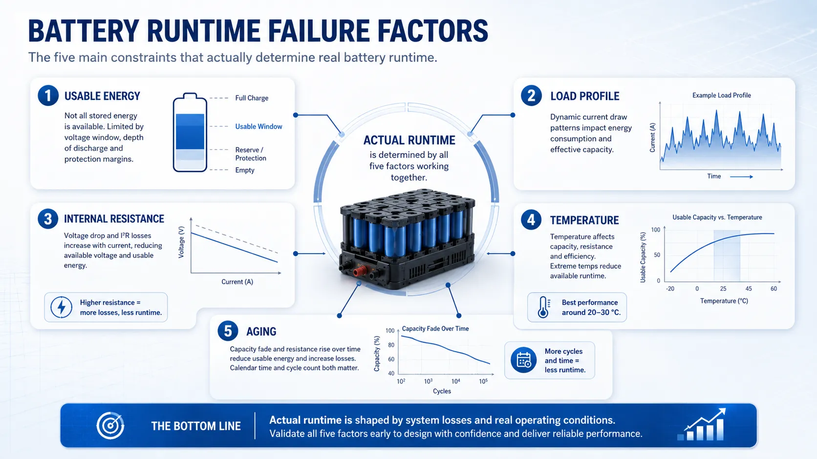
Runtime is not determined by capacity alone. In OEM projects, five constraints usually decide whether the battery can meet the target in a stable, manufacturable way.
| Constraint | Runtime Impact | Design Question |
|---|---|---|
| Usable energy | Only part of nominal Wh may be available before device cutoff. | What voltage or state-of-charge will define the end of runtime? |
| Load profile | Peaks and duty cycle can dominate energy use. | Which operating modes must be included in the test profile? |
| Internal resistance | High current causes voltage sag and heat. | Can the pack support peak current without early cutoff? |
| Temperature | Cold reduces available capacity and increases impedance. | Will the device be tested at room temperature only or across the real environment? |
| Aging margin | Capacity and impedance change over cycles and calendar life. | Must the runtime target be met at beginning of life or end of life? |
7. Worked Example 1: 36 W Backup Load for Six Hours
Suppose an industrial controller needs six hours of backup runtime at an average 36 W load. A simple calculation says 36 W x 6 h = 216 Wh. But the pack cannot be sized at exactly 216 Wh because conversion loss, cutoff voltage, reserve margin and aging must be considered.
| Item | Assumption | Calculation Result |
|---|---|---|
| Average load | 36 W | 216 Wh required at the load for 6 h |
| System efficiency | 90% | 216 / 0.90 = 240 Wh battery-side energy |
| Usable-energy and reserve factor | 85% | 240 / 0.85 = 282 Wh nominal pack target |
| Aging margin | 80% end-of-life capacity target | 282 / 0.80 = about 353 Wh if 6 h must be maintained at end of life |
This example shows why one runtime number can produce different pack sizes depending on the commercial promise. If the six-hour requirement is a new-pack laboratory target, the pack might be smaller. If six hours must be guaranteed after aging, in cold conditions, or under a higher peak load, the required nominal Wh increases.
| Hidden Risk | Validation Check | Supplier Decision |
|---|---|---|
| Load is not truly constant. | Measure power during startup, steady operation and alarm modes. | Model runtime with a realistic load profile. |
| Converter efficiency varies with load. | Test efficiency across expected current range. | Avoid using only the best-case efficiency point. |
| Cutoff occurs before low-voltage energy is used. | Confirm device cutoff and BMS cutoff thresholds. | Coordinate protection settings with device behavior. |
| Thermal rise changes performance. | Run runtime test in the final enclosure. | Adjust cell choice, layout or derating. |
8. Ah vs Wh: Why Voltage Must Be Part of the Discussion
Amp-hours are useful inside one battery voltage class, but they can mislead buyers when voltage changes. A 10 Ah, 3.7 V pack stores about 37 Wh. A 10 Ah, 14.8 V pack stores about 148 Wh. Both are 10 Ah, but their usable energy is very different.
This is especially important when comparing single-cell LiPo packs, multi-series lithium-ion packs and energy-storage modules. If a project compares only Ah, it may choose the wrong pack architecture. Wh makes the comparison fair because it includes voltage.
| Pack Example | Nominal Voltage | Capacity | Nominal Energy |
|---|---|---|---|
| 1S LiPo pouch pack | 3.7 V | 10 Ah | 37 Wh |
| 2S Li-ion pack | 7.4 V | 10 Ah | 74 Wh |
| 4S Li-ion pack | 14.8 V | 10 Ah | 148 Wh |
| 12.8 V LiFePO4 module | 12.8 V | 10 Ah | 128 Wh |
If the project is moving from a single-cell prototype to a higher-voltage pack, review the series vs parallel battery configuration guide before comparing Ah values across pack voltages.
9. Worked Example 2: Duty-Cycled IoT Load
Duty-cycled devices often have a low average current even though their peak current is high. A device may sleep at microamp or milliamp levels, wake for sensing, transmit data at a much higher current and then return to sleep. The runtime depends on the time-weighted average.
| Mode | Current | Duration per Cycle | Contribution |
|---|---|---|---|
| Sleep | 0.08 mA | 590 seconds | 47.2 mA-sec |
| Sensor active | 25 mA | 5 seconds | 125 mA-sec |
| Wireless transmit | 380 mA | 5 seconds | 1900 mA-sec |
| Total per 600-second cycle | – | 600 seconds | 2072.2 mA-sec |
Average current equals 2072.2 mA-sec / 600 seconds, or about 3.45 mA. A 2000 mAh cell divided by 3.45 mA suggests about 580 hours before adjustments. But that estimate still needs voltage cutoff, temperature, self-discharge, wireless retries, aging and the cell’s ability to support transmit pulses without voltage collapse.
| Buyer Lesson | Why It Matters |
|---|---|
| Do not size only from peak current. | Peak current is essential for voltage sag, but average current controls energy use. |
| Do not size only from sleep current. | A tiny sleep current hides communication and sensor events. |
| Include failed transmissions or retries. | Real wireless environments often consume more energy than lab demos. |
| Test in the final firmware state. | Firmware timing changes can change runtime more than the cell choice. |
10. Worked Example 3: Peak-Current Voltage Sag
A battery can have enough nominal energy and still fail the product because voltage sag triggers an early shutdown. Voltage sag is the temporary voltage drop caused by internal resistance and current demand. It becomes more serious at low state of charge, low temperature, high current, aged cells and long wire runs.
Engineering approximation
Voltage sag can be estimated as DeltaV = I x R. In a battery pack, R includes cell impedance, welds, protection circuit, connector, wires and PCB traces. The measured system value is more important than a single cell datasheet value.
| Scenario | Peak Current | Effective Resistance | Estimated Sag | Risk |
|---|---|---|---|---|
| Fresh pack, room temperature | 5 A | 80 mOhm | 0.40 V | Usually manageable if cutoff margin is adequate. |
| Cold pack | 5 A | 160 mOhm | 0.80 V | May trigger early low-voltage cutoff. |
| Aged pack | 5 A | 180 mOhm | 0.90 V | Runtime may appear acceptable until pulse events occur. |
| Long wire or weak connector | 5 A | 220 mOhm | 1.10 V | Connector and harness design may be the limiting factor. |
This is why high-pulse products need both an energy calculation and a pulse validation plan. If the protection circuit is selected only from average current, the pack may pass a static runtime calculation and still fail during motor startup, wireless transmission, heating, valve actuation or peak processor load.
Need Runtime Calculated Against the Real Load?
Send the voltage window, measured duty cycle, peak events, cutoff behavior, temperature range and runtime target. THOR Power can translate the calculation into a practical cell and pack specification for final-device validation.
11. Why Rated Capacity Is Not Fully Usable in the Final Device
Rated capacity is measured under defined laboratory conditions. A product does not usually operate under exactly those conditions. The final usable capacity depends on cutoff voltage, discharge current, temperature, cell aging, wiring loss, protection loss and the energy reserve the customer wants to keep for safe shutdown.
| Loss or Derating Factor | Typical Cause | Design Response |
|---|---|---|
| Cutoff voltage | Device or BMS stops discharge before all cell energy is used. | Coordinate cutoff thresholds and shutdown logic. |
| High discharge rate | Cell capacity and voltage are lower at higher current. | Select a cell with suitable discharge capability. |
| Low temperature | Impedance rises and available capacity falls. | Validate cold runtime or add thermal margin. |
| Converter loss | Buck, boost or inverter efficiency is below 100%. | Use measured efficiency across the actual load range. |
| Aging | Capacity fades and impedance increases over cycles and calendar life. | Define beginning-of-life and end-of-life runtime targets. |
| Manufacturing tolerance | Cell capacity, resistance and assembly values vary within limits. | Use incoming inspection and pack-level test controls. |
12. Battery Runtime With Inverters and DC/DC Converters
When the battery powers an inverter or DC/DC converter, calculate the load energy first, then divide by efficiency. For example, a 100 W AC load for 2 hours requires 200 Wh at the AC output. If the inverter efficiency is 88%, the battery must supply about 227 Wh before reserve and aging margin.
Efficiency is not a fixed magic number. It changes with input voltage, output voltage, load level, temperature and converter design. A converter may be efficient near its rated load but inefficient at very low load. For devices that spend long periods in standby, standby current and quiescent current can materially reduce runtime.
| Load Type | Calculation Basis | Common Mistake |
|---|---|---|
| DC load at battery voltage | Ah or Wh can work if measured correctly. | Forgetting cutoff and aging margin. |
| Boosted 5 V output | Use output Wh divided by boost efficiency. | Using 5 V current directly as battery current. |
| Buck output | Use output Wh divided by buck efficiency. | Assuming efficiency is constant at all loads. |
| AC inverter | Use AC Wh divided by inverter efficiency. | Ignoring idle consumption and surge current. |
For larger backup, inverter or storage-style applications, compare the runtime target with THOR Power’s energy storage battery options instead of forcing a small-device pack architecture into a high-energy application.
13. Fuel Gauge and Remaining-Runtime Estimation
Runtime calculation before production is different from remaining-runtime estimation in the field. A fuel gauge estimates state of charge or remaining capacity during use. Simple voltage-based estimation can be inaccurate because lithium battery voltage curves are nonlinear and load-dependent. Coulomb counting can drift if it is not calibrated. More advanced gauges combine voltage, current, temperature and battery models.
For products where the user interface displays remaining runtime, the pack and device team should define the algorithm early. A display that falls from 40% to shutdown in a short time can feel like a battery failure even if the pack meets its laboratory runtime specification. Good customer experience requires both real runtime and credible remaining-runtime reporting.
| Gauge Method | Advantage | Limitation |
|---|---|---|
| Voltage lookup | Simple and low cost. | Can be inaccurate under load, temperature change or flat voltage curves. |
| Coulomb counting | Tracks charge entering and leaving the pack. | Can drift without calibration and accurate current measurement. |
| Model-based gauge | Can improve estimation across load and temperature. | Needs correct battery profile, validation and firmware integration. |
14. How to Validate Battery Capacity and Runtime in the Final Device

The calculation should be validated through final-device testing or a test setup that accurately represents it. Cell-level capacity tests are useful, but they do not prove final runtime. Pack-level and device-level tests are needed because wiring, protection, firmware, enclosure temperature and cutoff behavior affect usable energy.
| Validation Stage | Purpose | Pass/Fail Question |
|---|---|---|
| Cell capacity review | Confirm candidate cell rating and discharge condition. | Does the selected cell meet capacity and current needs under relevant conditions? |
| Pack prototype test | Confirm pack output, protection, connector and basic capacity. | Does the prototype meet electrical and mechanical requirements? |
| Device runtime test | Measure runtime in the actual operating profile. | Does the device meet the customer runtime target? |
| Temperature test | Check runtime and shutdown behavior at operating temperature limits. | Does cold or heat cause early cutoff, swelling risk or performance drop? |
| Aging or cycle test | Estimate end-of-life runtime behavior. | Is the runtime promise still realistic after use? |
| Pilot production test | Confirm repeatability before mass production. | Do production samples match approved prototype performance? |
If you are still before prototype approval, use THOR Power’s battery pack production process as a practical reference for how prototype, validation and production stages connect.
15. From Runtime Requirement to Supplier Approval
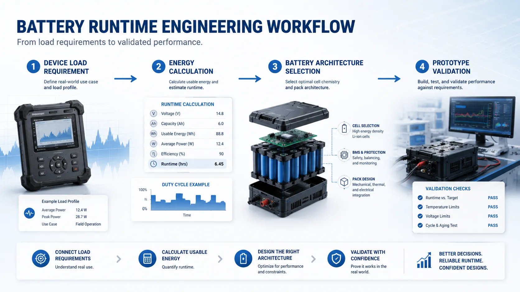
A professional battery supplier should not simply accept the target runtime and quote a capacity. The supplier should translate the runtime target into an architecture recommendation and explain the assumptions behind the recommendation. This is where engineering communication saves time.
15.1 OEM Project Inputs
- Target runtime and whether it must be met at beginning of life or end of life.
- Measured load profile, including average current, peak current and duty cycle.
- Required pack voltage, output voltage rails and converter or inverter details.
- Maximum size, weight target, mounting method, wire exit and connector type.
- Charging method, charge current, charge voltage and user-accessible safety requirements.
- Operating temperature, storage temperature, humidity and enclosure condition.
- Required documentation such as UN38.3, MSDS, IEC/CB, UL-related support or customer-specific reports.
15.2 Supplier Engineering Output
- Recommended chemistry, cell format and capacity range.
- Series/parallel architecture and pack nominal voltage.
- Protection circuit, BMS or PCM concept with current and cutoff logic.
- Connector, wire gauge, NTC and mechanical packaging proposal.
- Prototype sample plan, validation plan and production approval path.
- Risk notes where runtime depends on firmware, cutoff, temperature or load-profile assumptions.
| Supplier Response Quality | Weak Response | Strong Response |
|---|---|---|
| Runtime estimate | Quotes a pack capacity only. | Shows Wh, efficiency, margin and load-profile assumptions. |
| Architecture | Uses a generic pack. | Explains why a cell format and series/parallel design fit the project. |
| Risk handling | Ignores peak current and cutoff. | Reviews voltage sag, protection thresholds and thermal conditions. |
| Validation | Sends samples without a test plan. | Defines prototype, device-level runtime and pilot-run checks. |
16. What Standards and Transport Tests Can – and Cannot – Prove
Standards and transport tests are important, but they should not be treated as runtime guarantees. UN38.3 is a transport safety test framework, not a proof that a battery will power your product for a specified number of hours. IEC, UL-related and customer-specific tests may address safety, abuse, environmental or system requirements, but the final runtime still needs a device-level validation plan.
| Document or Test | Useful For | Not a Substitute For |
|---|---|---|
| UN38.3 | Transport safety documentation for lithium batteries. | Final-device runtime validation. |
| MSDS/SDS | Material and safety information. | Capacity or cycle-life proof. |
| IEC 62133-2 | Portable sealed secondary lithium cell/battery safety context. | Your exact device load profile. |
| IEC 62619 | Industrial lithium battery safety context. | Sizing the pack capacity for your product. |
| Customer runtime test | Real product performance under defined conditions. | General safety certification. |
17. How THOR Power Supports Battery Capacity and Runtime Engineering
THOR Engineering Perspective
In real OEM battery projects, the biggest challenge is usually not calculating Wh or Ah. The challenge is converting a theoretical runtime target into a validated battery architecture that fits the device, safety requirements and production conditions.
| THOR Approach | Engineering Purpose |
|---|---|
| Requirement analysis | Clarify runtime target, load profile, voltage window, mechanical limit and compliance scope before cell selection. |
| Battery architecture review | Translate usable energy and current capability into chemistry, cell format, series/parallel layout and protection direction. |
| Prototype validation | Test runtime, voltage sag, temperature behavior, connector performance and cutoff coordination in realistic device conditions. |
| Production approval | Confirm repeatability, documentation, process control and change management before stable mass production. |
THOR Power supports OEM teams that need more than a catalog battery. For runtime-sensitive products, the engineering process starts with application data: runtime target, load profile, size limit, charge method, operating condition and compliance needs. From there, THOR Power can recommend a pack architecture, protection approach, connector and wire configuration, NTC requirement and prototype validation plan.
This process is especially useful when the product has a tight enclosure, high peak current, variable duty cycle, long standby time, field temperature exposure or a user-facing runtime claim. In those cases, the best battery is not found by searching for the highest mAh number. It is designed by matching usable energy, current capability, voltage stability and manufacturability to the final device.
Planning a Custom Lithium Battery Pack?
Send your target voltage, runtime, load profile, size limit, connector, charging method and annual volume. THOR Power can review the runtime assumptions and recommend a custom battery pack with samples, UN38.3/MSDS support, and stable mass production.
18. Key Takeaways for Battery Runtime Calculation
- Use Wh-based calculation when voltage conversion, multiple rails or pack-voltage comparison is involved.
- Use Ah-based calculation only when load current is measured at the same battery voltage.
- Always include efficiency loss, cutoff voltage, temperature, aging and reserve margin.
- Duty-cycled products require a time-weighted average load model.
- Peak current can cause voltage sag and early cutoff even when nominal energy is sufficient.
- A calculator is the first estimate; final runtime must be confirmed in the real device.
19. Conclusion
Battery runtime calculation is not just a formula. It is a bridge between product promise and engineering reality. The correct estimate starts with Wh, Ah, average load and duty cycle, but the final battery pack must also account for converter efficiency, cutoff voltage, pulse current, temperature, aging, mechanical limits and production validation.
For OEM products, runtime calculation should become part of battery architecture design rather than a final verification step. When this work is done early, the team can avoid unrealistic capacity promises, unstable prototypes and late-stage redesign.
For early-stage planning, a calculator can help you understand the approximate energy target. For an OEM product, the next step is to turn that number into a manufacturable battery pack design with the right chemistry, cell format, protection circuit, connector, wire, NTC, charger compatibility and validation plan.
20. FAQ: Battery Runtime Calculation
What is the simplest battery runtime formula?
The simplest formula is runtime in hours equals battery capacity in Ah divided by average load current in A. Use it only when the current is measured at the same battery voltage.
Is Wh better than Ah for runtime calculation?
Wh is usually better when comparing packs with different voltages or when the device uses DC/DC conversion, because Wh includes voltage and represents stored energy.
Why does my device run shorter than the calculator result?
Common causes include converter loss, cutoff voltage, high discharge rate, cold temperature, pulse current, aging, wiring loss and an unrealistic average-load assumption.
How much safety margin should I add?
The margin depends on the product promise, temperature range, aging target, cell tolerance and validation plan. OEM projects should define whether runtime is required at beginning of life or end of life.
Can UN38.3 prove battery runtime?
No. UN38.3 supports lithium battery transport safety documentation. It does not prove that a pack will power a specific device for a specified runtime.
Why does peak current matter if average current is low?
Peak current can cause voltage sag, heat and protection shutdown. A product can fail during a short pulse even if average energy consumption looks acceptable.
21. Technical References
- NASA. Guidelines on Lithium-Ion Battery Use in Space Applications.
- NREL. Integration Issues of Cells into Battery Packs.
- Texas Instruments. How to Complete a Successful Learning Cycle for the Impedance Track Fuel Gauge.
- Analog Devices. A Closer Look at State of Charge (SOC) and State of Health (SOH) Estimation Techniques for Batteries.
- Analog Devices. An Efficiency Primer for Switch-Mode, DC-DC Converter Power Supplies.
- UNECE. UN Manual of Tests and Criteria, Revision 8 — Sub-section 38.3.
- International Electrotechnical Commission. IEC 62133-2:2017+A1:2021.
- International Electrotechnical Commission. IEC 62619:2022.