Battery Connector, Wire Gauge and NTC Selection Guide: Current Path, Voltage Drop, Crimping and Validation

Technically Reviewed By
Chief Scientist
Dr. Maximilian Weber is THOR Power’s Chief Scientist and a senior expert in lithium battery technology. His technical review focuses on battery safety, performance optimization, energy density and custom battery solution development.
Last technical review: September 2026

Written By
President of OEM Division & Custom Battery Specialist
Victor Xiong holds a Master’s degree from The Chinese University of Hong Kong, Shenzhen. He leads THOR Power’s OEM Division and focuses on custom battery solutions for global device brands, product developers and industrial customers.
| Written By | Technically Reviewed By |
|---|---|
| Victor Xiong President of OEM Division & Custom Battery Specialist. Victor Xiong leads THOR Power‘s OEM Division and focuses on custom battery development for global device brands, product developers and industrial customers. | Dr. Maximilian Weber Chief Scientist. Dr. Weber’s technical review for this article focuses on complete current-path resistance, connector derating, wire voltage drop and thermal behavior, crimp and harness workmanship, polarity and pinout control, NTC circuits and placement, final-device validation and production configuration control. |
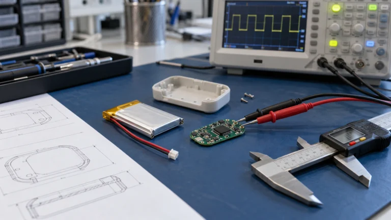
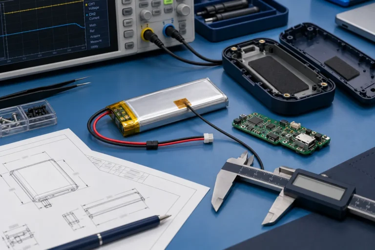
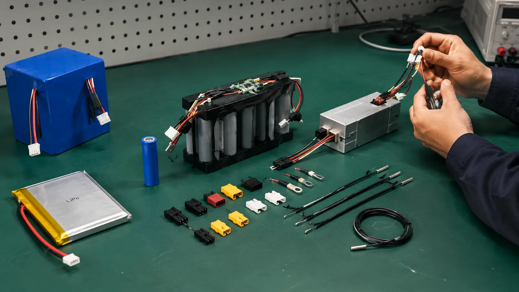
Before choosing a connector, wire gauge or NTC sensor, an OEM team should define the complete battery-to-device interface: current waveform, voltage-drop budget, connector contact system, crimp process, cable route, polarity, sensor curve, sensor location and production evidence. For visual identification of common families, pin counts and pitch, use the battery connector guide before finalizing the mating interface. This guide builds on the Custom Battery Pack Design Guide as the parent workflow and helps product teams avoid approving interface parts by catalog labels alone. Projects with non-standard connectors, wiring or sensing can be scoped through a custom battery engineering review.
A custom LiPo battery passed capacity, protection and bench-load tests. After the final enclosure was assembled, the device reset during motor startup, one connector terminal became hotter than the cells, and the charger reported an incorrect cold-battery condition. The cells and PCM were within specification. The failures came from three small interface details: excessive loop resistance, an inconsistent crimp and an NTC mounted where it measured the board instead of the limiting cell.
This is where many otherwise sound battery designs fail. The connector is selected from a catalog current label, the wire from an ampacity chart and the thermistor from the phrase “10 kOhm NTC.” Each choice can be individually plausible while the assembled battery-to-device interface remains electrically, mechanically or thermally unsuitable.
Quick Answer
Choose the connector, wire, crimp, pinout and NTC as one validated battery interface. Start with the measured battery-side waveform and device voltage margin; allocate a complete loop-resistance budget; select the exact contact, terminal and conductor construction; define crimp and strain-relief controls; specify the NTC curve, circuit and physical location; then validate the production-intent assembly in the final device and pilot build.
Four Approval Questions
1. Does the complete cell-to-device path stay inside the allowed voltage-drop and temperature limits? 2. Can the connector, crimp and harness survive the real mechanical and environmental life? 3. Does the NTC represent the temperature that should control charging or discharge? 4. Can normal production repeat the approved terminal, wire, tooling, pinout, sensor placement and final-test result?
Case Transparency Note
The engineering cases in this article are representative composite scenarios based on recurring battery-project patterns. They explain diagnostic and approval decisions without identifying a specific customer or presenting confidential project data as a named THOR Power case study.
📥 Free OEM Resource
Connector, Wire & NTC Requirement Checklist
Define your full battery interface requirement before asking a supplier to quote.
1. The Battery Interface Is a System Boundary, Not an Accessory List
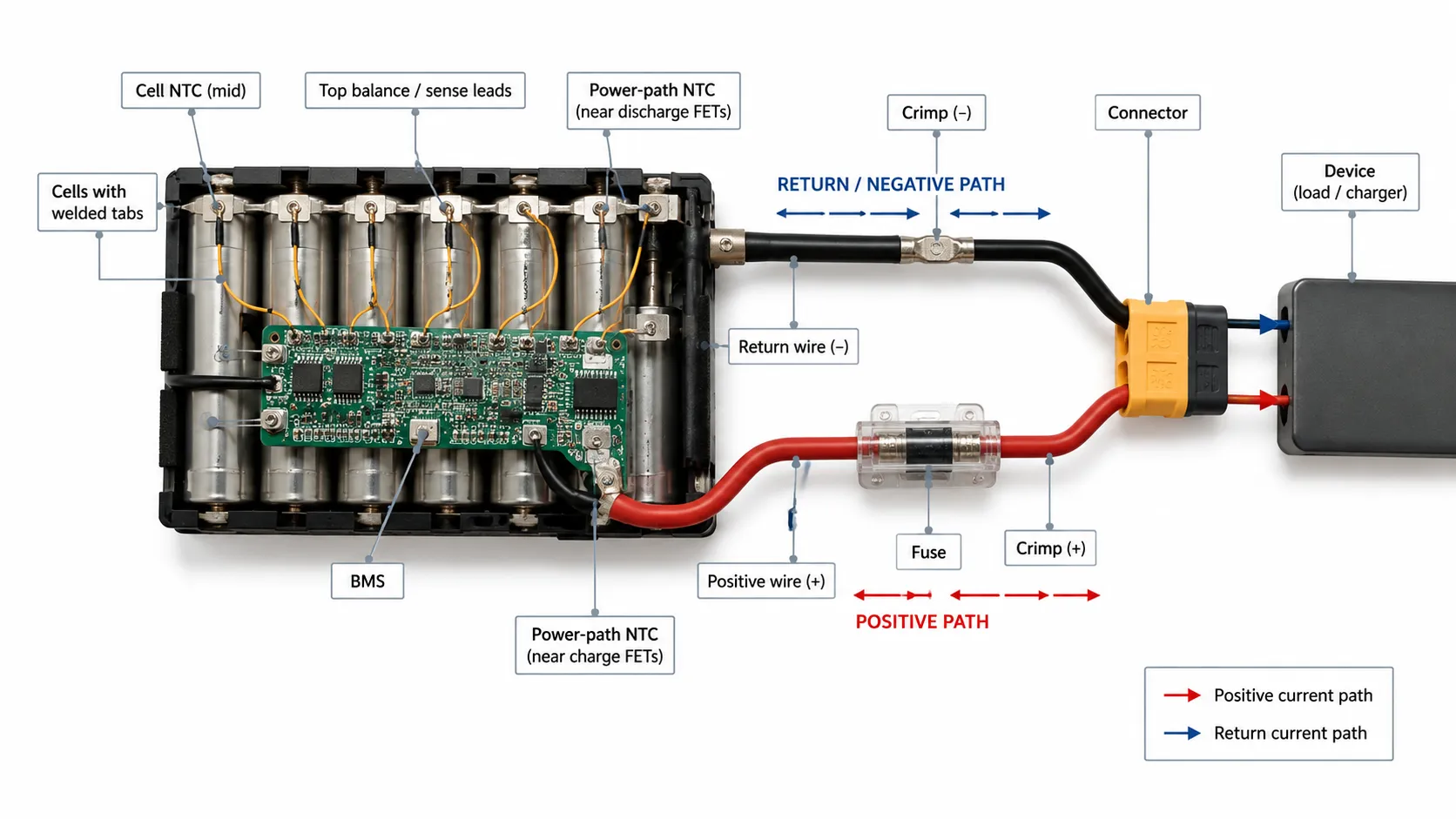
A battery interface carries power, mechanical loads and temperature information across the boundary between the pack and the host product. It includes the cell tabs or busbars, welds, PCM/BMS switching path, shunt, fuse, PCB copper, wire, crimps, terminals, connector housing, seals, auxiliary pins, sensor leads and every controlled joint between them.
The useful engineering question is not “Which connector and AWG should we use?” It is “Which complete interface keeps the device voltage, local temperature, mechanical retention, polarity and temperature-control decisions inside the approved requirements throughout product life?”
Core Engineering Principle
The interface is only as reliable as its highest-resistance joint, weakest retention point and least-representative temperature sensor. A connector family name, wire gauge or “10 kOhm NTC” label is not a complete specification.
The interface has three linked budgets that interact. A smaller wire can increase drop and heat; a stiffer wire can transfer force into the terminal or cell tab; a sealed connector can change cooling; and an NTC moved to simplify assembly can delay or misrepresent the thermal condition that should stop charging.
| Budget | What it must control | Typical evidence |
|---|---|---|
| Electrical | Allowed milliohms, loaded-voltage drop, I²R loss, current sharing and the fault-current path from cell to device. | Segment and total loop resistance, loaded voltage, temperature and fault-coordination results. |
| Mechanical | Mating retention, polarization, terminal retention, strain relief, bend radius, flex life, vibration, sealing and service handling. | Approved drawings, terminal-wire-tool combination, crimp data, retention, environmental and after-test inspection. |
| Temperature information | Which locations are measured, sensor accuracy and lag, open/short diagnosis, thresholds and charger/BMS response. | Exact NTC curve, circuit, placement drawing, thermal mapping, fault tests and production inspection. |
2. Freeze the Interface Requirement Before Choosing Parts
A connector, wire or NTC cannot be approved against a requirement that was never written. Phrases such as “20 A connector,” “thick wire,” “waterproof plug” or “10 kOhm sensor” leave the supplier to choose the test condition, temperature limit, viewing direction, sensor curve and production process. The requirement should define the chemistry and voltage window, the full battery-side current waveform, the device voltage-drop budget, cable lengths and environment, the exact connector counterpart and mating rules, power and auxiliary pin functions, the NTC curve and circuit, and the required samples and change-notification rules.
Requirement Warning
Do not let the supplier define the acceptance limit after the assembly is tested. The current waveform, voltage-drop budget, sensor locations, temperature limits, mating life and pass/fail rules should be agreed before the run. Otherwise a failing interface can be made to “pass” by shortening the pulse, changing the probe location or excluding connector and crimp resistance.
Use the downloadable Connector, Wire and NTC Requirement Checklist before asking a supplier to choose the interface. The checklist separates the power path, signal path, mechanical environment, temperature-control logic and required production evidence: record the measured current waveform and allowed device-side voltage drop; identify the exact connector halves, terminal cavities, mating-face view and auxiliary-pin functions; define conductor material, cross-section, insulation, length, flexibility, route and termination method; specify the NTC curve, divider or charger circuit, sensor locations and fault response; and define crimp tooling, process limits, pull-force plan, polarity inspection, resistance test and pilot-lot evidence.
3. Eight Gates for Connector, Wire and NTC Selection
The eight gates below convert a component request into an approvable battery interface. A project should not advance merely because a connector mates or a wire carries current on the bench; it advances when the evidence required by the current gate is complete or the remaining deviation is formally accepted.
| Gate | Engineering decision | Release evidence |
|---|---|---|
| 1 — Current path and drop | Define every current event and allocate the complete loop-resistance and loaded-voltage budget. | Waveform, resistance budget and section-by-section target. |
| 2 — Connector contact system | Select the exact housing, terminal, seal, wire range and mating counterpart under derated conditions. | Part numbers, derating basis, contact-resistance and temperature-rise plan. |
| 3 — Wire construction | Choose conductor and insulation by drop, heat, fault, flexibility and terminal compatibility. | Wire specification, loop calculation and installed thermal plan. |
| 4 — Crimp and strain relief | Freeze terminal-wire-tool geometry and the external load path. | Crimp height, pull-force, tooling, inspection and strain-relief controls. |
| 5 — Pinout and polarization | Define viewing direction, cavity functions, keying, sequence and mistake-proofing. | Controlled mating-face drawing and 100% polarity/pin test. |
| 6 — NTC curve and circuit | Match the exact thermistor curve to the divider, ADC/charger thresholds and fault logic. | Part/R-T table, circuit, conversion, thresholds and tolerance analysis. |
| 7 — Sensor placement | Place sensors where they represent the coldest, hottest or power-path condition being controlled. | Thermal map, placement drawing, attachment method and response data. |
| 8 — Validation and production | Test the production-intent interface in the final device and prove pilot-lot repeatability. | Traceable samples, raw data, controlled BOM, final-test limits and change matrix. |
4. Gate 1: Define the Complete Current Path and Allowed Voltage Drop
Begin with the battery-side waveform, not the device nameplate. Record continuous current, startup or inrush, pulse duration, repetition, low state of charge, cold operation, regenerative current and the fault events that the interface must either carry or help interrupt. For regulated constant-power loads, current often rises as battery voltage falls. For motors, radios, heaters and compressors, a measured waveform is more reliable than an average. The Battery Runtime Calculation Guide covers the loaded-voltage and minimum-voltage behavior that drives this current model.
Core Current-Path Formulas
Voltage drop: ΔV = I × Rloop
Conduction loss: Ploss = I² × Rloop
Maximum loop resistance: Rloop,max = ΔVallowed / Ievent
Conductor estimate: R = ρ × L / A
The loop includes both positive and return conductors and every series element: tabs or busbars, welds, PCM/BMS MOSFETs, shunt, fuse, PCB copper, crimp terminals, connector contacts and cable. A calculation that assigns the full budget to the wire can fail before the harness is assembled.
Example: a 12.8 V product allows 0.30 V of interface drop during a 25 A pulse. The complete loop-resistance budget is 0.30 V / 25 A = 12 mOhm. If the BMS, fuse and connector account for 7 mOhm under the approved condition, both wire runs and all crimps have only 5 mOhm remaining. At the full 12 mOhm budget, instantaneous interface loss is 25² × 0.012 = 7.5 W while the pulse is present.
| Current event | Data required | Approval check |
|---|---|---|
| Continuous load | Battery-side RMS or sustained current at minimum operating voltage and worst ambient. | Steady temperature of cells, BMS, fuse, connector, crimps and wire. |
| Peak or pulse | Amplitude, duration, repetition, SOC and temperature. | Device-side voltage, local heating, contact stability and no nuisance protection trip. |
| Motor stall or inrush | Worst credible event, not only normal startup. | Ride-through or controlled trip, connector arc risk and recovery. |
| Regenerative or reverse current | Direction, amplitude, SOC and connection state. | Contact path, charge FET/fuse coordination and overvoltage margin. |
| Fault-clearing event | Available fault current, fuse/BMS delay and conductor withstand. | No unacceptable wire, terminal or connector damage before interruption. |
Composite Engineering Case 1 — The Wire Carried the Current but the Product Shut Down Early
Project situation: A long battery harness measured 32 mOhm end to end after the connector and crimps were included. At a 15 A load, the interface dropped about 0.48 V and dissipated about 7.2 W.
Hidden risk: The short bench test did not exceed the wire insulation limit, but the device reached its undervoltage threshold early at low state of charge. The project had treated ampacity as the only wire requirement.
Engineering response: The team allocated a milliohm budget to the BMS, fuse, connector, crimps and wire, shortened the route, changed conductor size and reduced contact resistance. Loaded voltage was then repeated at low SOC and low temperature.
Buyer lesson: A harness can pass an ampacity check and still fail the product. Device-side voltage is often the first system limit.
5. Gate 2: Select the Exact Connector Contact System, Not a Catalog Amp Number
Connector current ratings are results from defined test conditions, not universal permissions. The exact terminal, wire size, number of loaded circuits, ambient temperature, housing, sealing, mating state and allowed temperature rise determine the usable current. The family name alone does not identify the validated contact system.
| Decision area | What must be defined | Why the family label is insufficient |
|---|---|---|
| Current and temperature | Continuous/pulse waveform, ambient, adjacent circuits, wire size and allowed contact temperature. | Current changes with test method, cooling, circuit loading and termination. |
| Contact resistance | Initial and aged milliohms, plating, pair count and measurement method. | Small resistance growth creates significant I²R heat. |
| Mating and retention | Mating cycles, latch, insertion/withdrawal force, vibration and service behavior. | A low-resistance contact can still back out, fret or partially mate. |
| Polarization and touch safety | Keying, shrouding, exposed live contacts and mis-mating risk. | Mechanical compatibility can still allow reverse polarity or unsafe access. |
| Environment | Ingress, condensation, dust, chemicals, UV, temperature and flammability. | The same family may have different sealed and material options. |
| Manufacturing | Approved terminal, wire range, strip length, tooling, crimp height and inspection. | Performance depends on the finished termination, not only the housing. |
Parallel power contacts do not automatically multiply current capability. Unequal terminal resistance, wire length, crimp quality and engagement sequence can cause one path to carry more current. Parallel contacts require current-sharing, single-contact-fault and thermal validation, especially when one terminal can mate or disconnect first. This is common in 18650 / 21700 motor and robotics packs with high pulse current.
Composite Engineering Case 2 — The Connector Rating Passed but the Contact Pair Ran Hot
Project situation: A pack delivered 20 A continuously through a connector family advertised for higher current.
Hidden risk: The final assembly used a smaller terminal option, two adjacent loaded circuits and a warm sealed enclosure. Measured resistance across the mated pair and terminations was about 5 mOhm, creating about 2 W of local loss at 20 A.
Engineering response: The team changed the terminal/contact option, housing and crimp process, then repeated resistance and temperature-rise tests after mating cycles and vibration.
Buyer lesson: Approve the exact contact system and installed condition. A connector family current label cannot approve every terminal, wire and enclosure combination.
6. Gate 3: Size Wire by Voltage Drop, Heat, Fault Protection and Flexibility
Wire gauge is not selected from ampacity alone. IEC 60228 can support conductor cross-section and resistance requirements, while UL 758 covers evaluated Appliance Wiring Material constructions. Neither reference proves that the installed battery harness meets the device voltage, temperature, flex or fault requirements.
Wire-Selection Rule
The correct wire is the smallest validated construction that meets voltage-drop, thermal, fault, flexibility and termination requirements with production margin. “Use the thickest wire that fits” can create an uncrimpable terminal, excessive stiffness, poor routing or new stress at the cell tabs.
| Design question | Engineering check | Failure when ignored |
|---|---|---|
| What is the real load model? | Use minimum-voltage current for regulated loads; measure motor and pulse waveforms. | Wire appears adequate at nominal voltage but drops excessive voltage near discharge. |
| What is the complete loop length? | Include positive and return conductors, pigtails, service loops and production tolerance. | Only one-way length is used, underestimating resistance. |
| How is the wire installed? | Review bundle size, sealed enclosure, airflow, flexing and adjacent heat. | Bench wire stays cool while the installed harness overheats. |
| Does the terminal accept it? | Use the terminal manufacturer approved conductor and insulation range. | Strands are trimmed, barrel fill is wrong or insulation support is ineffective. |
| What happens during a fault? | Coordinate fuse/BMS clearing with conductor and connector energy withstand. | Normal operation passes but a stalled load or short damages the harness. |
| What must production control? | Conductor material, strand count, cross-section, insulation, length and supplier. | A visually similar substitute changes resistance, flexibility or crimp behavior. |
Composite Engineering Case 3 — Thicker Wire Created a New Termination Failure
Project situation: An OEM increased wire size after observing voltage drop in a motorized product.
Hidden risk: The larger conductor did not fit the approved terminal barrel. Operators trimmed strands and the stiffer cable transferred movement into the crimp and cell-tab region.
Engineering response: The interface was redesigned as a complete path: route length and connector resistance were reduced, an approved terminal-wire combination was selected, and strain relief was relocated before vibration and loaded-voltage tests were repeated.
Buyer lesson: Lower wire resistance is not useful if the termination becomes uncontrolled or the mechanical load moves into a weaker joint.
7. Gate 4: Treat the Crimp and Strain Relief as Controlled Components
A reliable crimp is a controlled electrical and mechanical joint among a specified terminal, conductor and tool. Workmanship guidance from NASA and connector manufacturers emphasizes wire preparation, terminal selection, tooling, crimp geometry and inspection. Continuity alone cannot confirm conductor compression, low resistance or long-term retention.
| Process control | What to freeze | Evidence |
|---|---|---|
| Wire preparation | Strip length, no damaged strands, conductor brush and insulation position. | First-article inspection and periodic samples. |
| Conductor crimp | Crimp height/width, bellmouth, terminal position and approved applicator/tool. | Cross-section or equivalent qualification, crimp-height records and tool ID. |
| Insulation support | Insulation barrel position and compatible insulation diameter. | Visual limits and pull/flex evidence. |
| Mechanical retention | Terminal lock, housing retention and external strain-relief point. | Terminal push/pull checks, cable pull and vibration inspection. |
| Process capability | Tool wear, setup verification, lot sampling and operator instructions. | Pilot-lot data, maintenance records and reaction plan. |
| Electrical result | Joint resistance and loaded temperature where current is significant. | Four-wire or controlled resistance test and thermal validation. |
Composite Engineering Case 4 — The Prototype Harness Passed, Then Became Intermittent in Pilot Production
Project situation: A hand-crimped prototype passed continuity and initial device testing.
Hidden risk: Pilot units showed variable strip length and conductor position. Several terminals had reduced conductor brush and inconsistent insulation support, so repeated flexing transferred stress into the conductor crimp.
Engineering response: The release package added an approved terminal-wire-tool combination, crimp-height limits, pull-force sampling, terminal-retention inspection, external strain relief and reaction rules for out-of-limit results.
Buyer lesson: A good-looking prototype crimp does not prove a repeatable production process. Approve geometry, tooling and process evidence together.
Key crimp rules: do not trim strands to force a conductor into an undersized terminal barrel; do not use the insulation crimp as the only strain relief for a moving or serviceable harness; do not allow solder to wick into a flexing conductor unless the transition and strain relief are specifically designed and validated; and do not approve a hand-tool prototype and then move to another terminal, applicator or automatic process without requalification.
8. Gate 5: Freeze Polarity, Pin Numbering, Keying and Auxiliary-Pin Sequence
Connector failures are often documentation failures. A drawing may show the mating face, wire-entry face, device-side view or battery-side view; cavity numbers can appear mirrored between them. The approved drawing must identify the connector half, part number, terminal gender, viewing direction, cavity number, polarity, wire color and function of every pin. Power connectors may also carry NTC, identification, wake, communication, interlock, precharge or charger-detect signals. These pins create system behavior, and their reference ground, engagement sequence, ESD exposure, current, isolation and failure response must be reviewed with the host electronics and BMS — a topic covered in the PCM/BMS Selection Guide.
| Control | Weak practice | Production-ready practice |
|---|---|---|
| Viewing direction | A 2D cavity drawing with no face identified. | Mating-face illustration plus wire-entry illustration, each clearly labeled. |
| Polarity | Red and black wire color is the only control. | Keying, cavity assignment, controlled drawing and 100% electrical polarity test. |
| Connector revision | A mechanically similar housing is treated as equivalent. | Exact mating pair, key code and incompatibility review with earlier versions. |
| Auxiliary pins | NTC or communication leads are added without sequence review. | Pin function, ground reference, contact sequence, current limit and fault behavior defined. |
| Terminal retention | Continuity is checked but a backed-out terminal is not detected. | Cavity inspection, terminal push/pull control and connector-position assurance where needed. |
| End-of-line test | One continuity result approves the harness. | Polarity, cavity map, NTC/ID range, communication and isolation checks as applicable. |
Composite Engineering Case 5 — The Pinout Was Correct on Paper and Reversed in Assembly
Project situation: A receptacle drawing was prepared from the mating face while the harness work instruction was interpreted from the wire-entry side.
Hidden risk: The same cavity numbers were mirrored, placing positive and negative in opposite positions. Wire colors appeared correct when viewed from each document separately.
Engineering response: The team issued a controlled mating-face and wire-entry drawing, identified both connector part numbers, added cavity labels, changed the keying and introduced 100% polarity and auxiliary-pin inspection.
Buyer lesson: Color is a secondary control. Viewing direction, keying and end-of-line electrical tests should make a drawing mistake unable to reach the customer.
9. Gate 6: Specify the NTC Curve and Measurement Circuit, Not Only “10 kOhm”
An NTC thermistor is defined by more than its resistance at 25°C. Specify R25, tolerance, beta value with its reference temperatures or a complete resistance-temperature table, package, insulation, operating range and the measurement circuit. Beta values are not directly comparable unless the temperature points used to define them are the same.
NTC Beta Relation
A common approximation is: 1/T = 1/T0 + (1/B) × ln(R/R0), where temperature is in kelvin. This is useful for screening, but the approved design should use the exact manufacturer R/T data, tolerance and the actual divider or charger circuit.
Two 10 kOhm thermistors can produce different readings away from 25°C. Using the beta approximation, a 10 kOhm B3435 thermistor is about 2.98 kOhm at 60°C, while a 10 kOhm B3950 thermistor is about 2.49 kOhm. A charger or BMS calibrated for one curve can apply the wrong hot or cold threshold to the other. A common divider relationship is VADC = Vref × RNTC / (Rpullup + RNTC). The result changes if the NTC is placed above rather than below the pull-up, and the design must include reference tolerance, pull-up tolerance, ADC range, input leakage, filtering, wiring resistance and firmware conversion.
| NTC requirement | What must be specified | Failure if only “10 kOhm” is given |
|---|---|---|
| Resistance curve | R25, beta definition or R/T table, tolerance and operating range. | Wrong threshold away from room temperature. |
| Electrical circuit | Pull-up/bias value, supply/reference, ADC range, filter and conversion. | ADC saturation, poor resolution or reversed interpretation. |
| Self-heating | Bias current and thermistor dissipation in the installed environment. | Sensor reads warmer than the intended surface. |
| Fault diagnosis | Expected range for open wire, short circuit and connector disconnect. | Broken sensor is interpreted as a valid temperature. |
| Mechanical form | Bead, chip, probe, ring lug, insulation, lead length and attachment. | Thermal lag, short risk or unit-to-unit variation. |
| Control response | Charge/discharge thresholds, delay, hysteresis, recovery and logging. | Nuisance shutdown or operation outside the intended boundary. |
Composite Engineering Case 6 — The Replacement NTC Had the Same Room-Temperature Label
Project situation: A supplier substituted another 10 kOhm thermistor during a component shortage.
Hidden risk: Room-temperature inspection passed because both parts were near 10 kOhm at 25°C. Their beta curves differed, shifting the charger threshold at elevated and low temperature.
Engineering response: The specification was changed to an exact approved part or controlled R/T table, circuit, tolerance stack, threshold table and end-of-line range. The substitution was then revalidated across temperature.
Buyer lesson: R25 is only one point on the curve. The sensor, circuit and firmware conversion must be controlled as one measurement system.
10. Gate 7: Place Sensors Where the Relevant Failure Modes Occur
A correct NTC curve cannot protect a location it does not measure. Sensor placement should answer a defined control question: Is the coldest cell warm enough to charge? Is the hottest cell group inside its discharge limit? Are the BMS MOSFETs, fuse, busbar, connector or cable lug becoming the limiting component?
| Sensor function | Representative placement question | Validation need |
|---|---|---|
| Cold-charge permission | Which cell or group remains coldest after soak and during preheat or charge start? | Cold-soak map, sensor lag, tolerance and charger/firmware enter-exit behavior. |
| Cell discharge protection | Which cell group becomes hottest under repeated duty and low SOC? | Installed thermal map, cell-to-sensor contact and repeated-cycle response. |
| Power-path protection | Can MOSFETs, fuse, busbar, connector or crimp exceed the cell temperature? | Local temperature and resistance under continuous and pulse loads. |
| Enclosure or ambient control | Does enclosure air meaningfully represent the cell or electronics condition? | Correlation across orientation, airflow and neighboring heat sources. |
| Redundant supervision | Which independent locations are needed for the hazard and system architecture? | Plausibility logic, disagreement response and production test coverage. |
Composite Engineering Case 7 — The NTC Reported a Safe Pack While the Connector Was Hottest
Project situation: A temperature sensor on the BMS PCB stayed below the discharge limit during repeated high-current operation.
Hidden risk: Infrared and contact measurements showed that one connector terminal and crimp were much hotter because local resistance had increased. The BMS-board NTC was physically incapable of detecting that hotspot in time.
Engineering response: The design reduced contact and crimp resistance, added a power-path thermal check to validation and defined resistance/temperature acceptance limits. The final product did not rely on the cell or board NTC to compensate for a defective contact.
Buyer lesson: Temperature sensing supports control only at measured locations. Hotspots should first be prevented by component and process design, then verified by targeted measurements.
11. Gate 8: Validate the Production-Intent Interface in the Final Device
A connector datasheet, wire certificate, crimp drawing and NTC part number are design inputs. They do not prove the finished battery assembly. Final validation should use the production-intent cells, PCM/BMS, fuse, terminals, wire, connector, sensor attachment, enclosure, charger and device firmware with a common sample identity. Voltage, current, temperature, BMS state and product behavior should share a common time base. A final statement such as “connector passed 20 A” is not enough unless the duration, ambient, enclosure, circuit loading, measurement location, mating history and acceptance criteria are recorded. Installed heat behavior is covered further in the battery thermal and safety guides.
| Validation area | What to test | Acceptance evidence |
|---|---|---|
| Loop resistance and voltage drop | Four-wire or controlled low-resistance measurement of sections and total path; loaded device voltage at continuous and peak current. | The interface remains inside allocated milliohm and device-voltage budgets. |
| Thermal performance | Contacts, crimps, wire, fuse, BMS and nearby cells at worst load, ambient, bundle and enclosure condition. | No component exceeds its approved temperature or creates an uncontrolled hotspot. |
| Peak and pulse behavior | Startup, radio transmit, motor stall, inverter inrush and repeated pulses at low SOC and temperature. | No nuisance cutoff, excessive sag, contact arcing or cumulative heating. |
| Crimp and retention | Crimp height, pull force, terminal retention, conductor/insulation position and process variation. | The approved terminal-wire-tool combination remains stable across production. |
| Mating and environment | Mating cycles, vibration, flexing, ingress, contamination and service handling. | Contact resistance, retention and sealing remain within limits after life exposure. |
| Polarity and pinout | 100% polarity, cavity, continuity and auxiliary-signal inspection using the approved viewing direction. | No mirrored drawing, back-out or miswired NTC/communication path. |
| NTC accuracy and response | Resistance/ADC value across temperature, placement, lag, open/short faults and recovery. | Charger/BMS thresholds represent the intended physical locations and fault states. |
| Pilot production | Repeat critical tests across terminal, wire, tool and component lots. | Normal production remains equivalent to the approved sample and BOM. |
Safety Boundary
Do not improvise high-energy short-circuit, arc, overload or destructive connector tests on a normal engineering bench. Abnormal-condition work requires the correct standard, risk assessment, fixtures, instrumentation, containment and trained personnel.
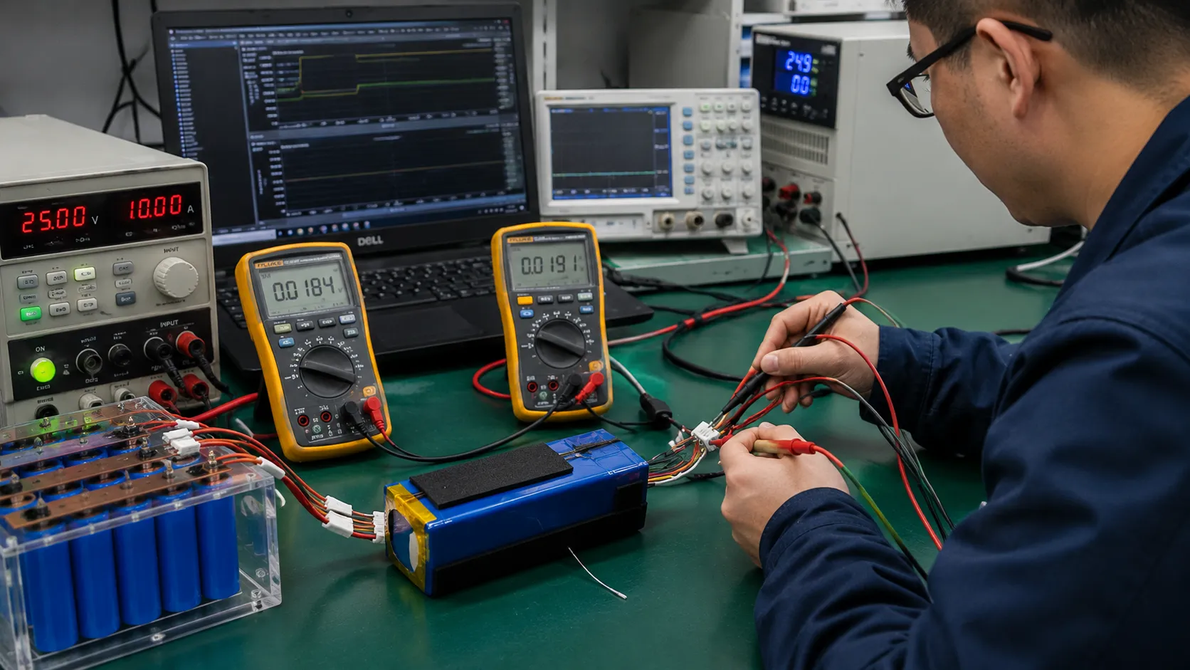
Need the Battery Interface Reviewed Before Harness Release?
Send the load waveform, voltage-drop budget, mating connector, pinout, wire route, environmental limits and NTC requirements. THOR Power can review the complete current path, crimp, polarity, sensor placement and production controls.
12. How the Interface Changes by Battery Type
| Project type | Typical interface priorities | Frequent buyer mistake |
|---|---|---|
| Compact single-cell LiPo | Low-profile polarized connector, fine flexible wire, controlled wire exit, PCM/NTC fit, low standby loss and local strain relief. | Choosing by appearance while ignoring cavity view, pull direction, tab stress and device assembly space. |
| 18650 / 21700 motor or robotics pack | Peak-current contact resistance, loop resistance, crimp temperature, latch retention, vibration and pulse-loaded voltage. | Selecting by continuous current and Ah while ignoring startup, stall and connector heating. |
| LiFePO4 backup or energy-storage module | Higher-current lugs/connectors, touch protection, precharge/interlock, multiple sensors, service isolation and communication harness. | Treating the external interface as a simple two-wire output and omitting sequencing or fault containment. |
| Special custom battery pack | Non-standard pinout, mixed power/signal interface, waterproofing, flexing, blind mating, redundancy and configuration control. | Approving one prototype cable without freezing terminals, tooling, NTC curve and final-test method. |
For compact device projects, review Custom LiPo Batteries. For motorized and pulsed-current products, review 18650 / 21700 Battery Packs. For backup and energy-storage applications, review energy storage battery models and Lithium-ion Battery Packs.
13. What Connectors, Wires and NTCs Can — and Cannot — Protect
| Function | A correct interface can support | It cannot replace |
|---|---|---|
| Power delivery | A low-resistance current path with controlled loaded voltage and heat. | Cells, BMS or fuse that are undersized for the load. |
| Mechanical reliability | Polarized mating, retention, strain relief and environmental sealing. | An enclosure or service process that applies uncontrolled loads. |
| Temperature supervision | Representative cell and power-path data with defined fault detection. | Protection for unmeasured hotspots or a sensor with poor thermal contact. |
| Fault response | A conductor and connector path coordinated with protective clearing. | Unlimited short-circuit energy or independent secondary protection where required. |
| Manufacturing repeatability | Controlled terminals, wire, tooling, crimp limits, pinout and test records. | Automatic equivalence after a connector, wire or NTC substitution. |
| Certification support | Evidence for the evaluated battery configuration and standard scope. | Automatic certification of the finished pack or host product from component ratings alone. |
14. Common OEM Mistakes in Battery Interface Design
| Mistake | Why it fails | Better approval rule |
|---|---|---|
| Selecting by connector catalog current | The exact terminal, wire, circuit count, ambient, housing and mating life may differ from the rating condition. | Approve resistance and temperature rise for the exact contact system. |
| Choosing wire from AWG/ampacity alone | Round-trip length, connector/BMS resistance and device cutoff can dominate. | Allocate a total loop budget and validate the installed harness. |
| Using wire too large for the terminal | Strand trimming, poor barrel fill and stiffness create new electrical and mechanical risks. | Use an approved terminal-wire construction and routing plan. |
| Treating continuity as crimp approval | Continuity does not prove compression, resistance, retention or life. | Control crimp geometry, tooling, pull force, resistance and pilot variation. |
| Relying on wire color for polarity | Color and viewing-direction errors can still be assembled. | Use keying, cavity control and 100% electrical test. |
| Specifying only “10 kOhm NTC” | The curve, circuit and thresholds can be wrong away from 25°C. | Freeze the exact R/T behavior, circuit, placement and fault response. |
| Placing one NTC on the BMS board | The coldest cell or hottest contact can be elsewhere. | Map the installed thermal field and assign each sensor a control function. |
| Allowing unreviewed substitutions | A visually similar terminal, wire or NTC can change resistance, crimping or temperature conversion. | Use controlled alternates and a defined revalidation matrix. |
15. Certification, Component Ratings and Product Validation Answer Different Questions
IEC 62133-2 addresses safety requirements and tests for portable sealed secondary lithium cells and batteries, while IEC 62619 addresses secondary lithium cells and batteries used in industrial applications, including stationary applications. These standards can include assembly and safety expectations, but they do not select the correct connector, wire gauge, crimp or NTC for a buyer’s exact host product. IEC 60228 can support conductor resistance and cross-section definitions, UL 758 applies to evaluated Appliance Wiring Material constructions, and connector/terminal manufacturers provide product-specific current, derating and crimp requirements. Each document answers only its defined scope. Review THOR Power’s battery certificates and compliance documents against the exact production configuration.
| Evidence type | What it can support | What it does not prove by itself |
|---|---|---|
| Connector product specification | Contact, terminal, wire range, current/temperature test data, mating and environmental requirements. | Suitability in another housing, ambient, circuit count, wire or termination process. |
| IEC 60228 / conductor data | Cross-section, construction and resistance-related requirements for defined conductor classes. | Installed harness temperature, voltage drop, flex life or terminal compatibility. |
| UL 758 AWM recognition | Evaluated wire construction and intended-use information under the applicable style. | That every AWM style is correct for every battery, market or moving harness. |
| Crimp workmanship guidance | Requirements and inspection methods for controlled cable and harness terminations. | Performance after an unapproved terminal, wire or tool substitution. |
| IEC 62133-2 / IEC 62619 | Battery safety requirements and tests within their application scopes. | Automatic approval of connector, pinout, NTC placement or final host product. |
| Supplier bench test | A defined performance or failure question for the tested interface. | Final-device behavior or production repeatability unless specifically represented. |
| Pilot production validation | That normal manufacturing can repeat the frozen interface design. | Compliance with a standard not included in the plan. |
16. Move From a Successful Harness to Repeatable Production
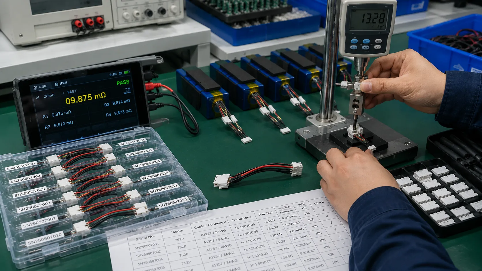
The production question is not whether one engineer can build a good cable. It is whether normal tools, operators, material flow and inspection can repeat the approved resistance, crimp geometry, pinout and sensor placement without adjustment or hand-selected parts. A pilot lot should use intended terminals, wire, tools, work instructions, operators and final-test equipment. Select samples across the run, not only the first unit or the unit prepared for a customer visit. A controlled battery pack production process preserves crimp height, pull force, loop resistance, terminal retention, wire length, cavity map, NTC resistance and attachment location across the lot.
Composite Engineering Case 8 — The Golden Harness Passed but the Pilot Lot Did Not
Project situation: A carefully hand-built reference harness passed voltage-drop, temperature, flex and enclosure tests.
Hidden risk: Normal production used a different applicator setup and variable wire strip length. The average continuity result remained good, but loop resistance and terminal retention spread widened across the lot.
Engineering response: The release package added tool setup verification, crimp-height and pull-force limits, section-resistance checks, cavity/polarity test, NTC range and first-article inspection, then repeated the pilot build.
Buyer lesson: A golden harness proves that one assembly can work. A pilot lot proves whether the normal process can repeat it.
17. Final Battery Interface Production Approval Gate
The interface is ready for production release only when the approved requirement, tested configuration and manufacturing controls point to the same design. Open issues may remain, but each must have a documented owner, risk decision and revalidation plan.
| Release item | Evidence required | Approval question |
|---|---|---|
| Requirement matrix closed | Every interface requirement has a result, accepted deviation or evidence owner. | Can the team explain what is approved and what remains open? |
| Sample configuration traceable | Exact connector, terminal, wire, tool, pinout, NTC, materials and exposure history. | Can the tested assembly be distinguished from every other build? |
| Loop budget passed | Segment and total resistance, loaded voltage and thermal results at critical conditions. | Did the full path meet the device voltage and heat limits? |
| Mechanical integration passed | Routing, bend radius, strain relief, mating, retention and environmental results. | Did the evidence represent the closed final product? |
| NTC system validated | Curve, circuit, placement, thresholds, lag, open/short and recovery results. | Does measured temperature represent the controlled condition? |
| Pilot lot accepted | Units sampled across normal production with critical-to-quality data. | Can ordinary production repeat the approved result? |
| Change control approved | Review authority, notification route and revalidation matrix. | Will a future substitution trigger the right review? |
Failure-Closure Rule
A failed interface test is not closed when the connector cools down or the device starts working again. It is closed only when the root cause is supported by evidence, the corrective action is documented, the affected tests are repeated and the production controls prevent recurrence.
18. How THOR Power Supports Connector, Wire and NTC Engineering
In real OEM battery projects, connector, wire and NTC problems usually appear at the boundary between a good battery pack and the final device. The engineering task is to convert current, voltage drop, heat, motion, polarity and sensing assumptions into an interface that can be built, tested and repeated in production.
THOR Power supports custom LiPo pouch batteries, lithium-ion battery packs, 18650 / 21700 packs, LiFePO4 backup and energy-storage batteries, and custom special battery packs. Interface review begins with the measured current waveform, device voltage window, physical installation and temperature-control strategy rather than a connector photograph or requested wire gauge. Depending on the project, the engineering scope can include connector and terminal screening, loop-resistance budgeting, wire and fuse coordination, pinout and polarity review, crimp-process definition, NTC curve and circuit confirmation, sensor-placement review, production-intent samples, loaded-voltage and temperature testing, pilot-lot review and change control. Final product approval remains shared: the battery supplier controls the pack interface and manufacturing process, while the OEM controls the host product, charger, firmware, installation, use conditions and market requirements.
19. Key Takeaways for OEM and ODM Buyers
- The connector, terminal, wire, crimp, pinout and NTC form one battery interface; approving each part separately does not approve the assembled path.
- Allocate a complete loop-resistance and loaded-voltage budget across BMS, fuse, contacts, crimps and both conductors.
- Connector current labels require derating and validation for the exact terminal, wire, ambient, loaded circuits, enclosure and mating life.
- Wire gauge must satisfy voltage drop, temperature, fault coordination, flexibility and terminal compatibility — not ampacity alone.
- Crimp quality is a controlled process defined by terminal, conductor, tooling, geometry, retention and resistance; continuity alone is not enough.
- A 10 kOhm NTC is not a complete specification. The curve, circuit, placement, thresholds and fault response must match.
- Validate the production-intent interface in the final device, prove pilot-lot repeatability and revalidate changes that can affect resistance, mechanics or temperature measurement.
20. Conclusion
Battery connector, wire and NTC approval is a chain of evidence, not a collection of catalog values. The interface must deliver the required current without unacceptable voltage drop or heat, remain mechanically secure throughout product life, report the temperature that actually controls the system and be repeatable under normal production conditions. For OEM and ODM teams, the practical goal is not the thickest cable or highest-current connector. It is a controlled, production-intent interface whose exact parts, current path, crimp process, pinout, sensor system and validation evidence can be understood, repeated and reviewed when a future change occurs.
Planning a Custom Battery Interface?
Send the current waveform, device voltage window, cable route, connector counterpart, pin functions, NTC requirements and existing test data. THOR Power can help identify whether the limiting risk is contact heating, harness voltage drop, crimp variation, mis-mating, sensor conversion or thermal placement.
21. FAQ: Battery Connector, Wire Gauge and NTC Selection
How do I choose the right connector for a battery pack?
Start with voltage, continuous and peak current, allowed temperature rise, contact resistance, circuit count, wire size, mating cycles, retention, keying, ingress and service conditions. Approve the exact housing, terminal, seal, mating part and crimp process; a connector-family current label is not enough.
How do I calculate battery wire gauge?
Define the battery-side current waveform and maximum allowed device-side voltage drop. Convert the drop into a complete loop-resistance budget, subtract BMS, fuse, connector and crimp resistance, then select a conductor that also passes temperature, fault, flexibility and terminal-compatibility checks.
Is thicker battery wire always better?
No. Lower resistance can help voltage drop and heating, but oversized wire may not fit the terminal, may require strand trimming, may be too stiff for the enclosure and may transfer stress into the connector or cell tabs. Use the smallest validated construction that meets all requirements with margin.
Can I multiply connector current by the number of parallel pins?
Not without validation. Current sharing depends on contact resistance, wire and PCB geometry, crimp quality and engagement sequence. One terminal can carry more than its intended share. Validate current sharing, temperature and the effect of one contact failing or mating first.
Why does a connector get hot below its catalog rating?
The final assembly may have higher contact or crimp resistance, warmer ambient, more loaded circuits, smaller wire, partial mating, contamination or less cooling than the rating test. Measure milliohms, loaded voltage and temperature in the installed condition and after the required mating/environmental life.
How much voltage drop is acceptable in a battery harness?
There is no universal value. The limit depends on device minimum voltage, BMS cutoff, load waveform, low-SOC voltage, temperature, aging and user behavior. Define the device-side voltage requirement first, then allocate a milliohm budget across the complete interface.
Should battery wires be crimped or soldered?
Use the termination method approved for the connector, conductor, environment and production process. Controlled crimps are common for repeatable harnesses. Soldered joints can be appropriate in specific designs, but solder wicking, flex transition, insulation, strain relief and process control must be addressed.
What NTC should I use for a lithium battery pack?
Specify an exact thermistor or controlled R25 and R/T curve, tolerance, package, lead insulation and operating range. Confirm the divider or charger circuit, ADC conversion, thresholds, placement, self-heating and open/short response with the BMS or charger.
What is the difference between 10 kOhm B3435 and B3950 NTCs?
Both can measure 10 kOhm at 25C, but their resistance changes differently away from 25C. A charger or BMS calibrated for B3435 can interpret B3950 incorrectly at hot or cold thresholds unless the conversion or resistor network is updated and validated.
Where should the battery NTC be placed?
Place the sensor where it represents the temperature that controls the decision. Charging may need the coldest representative cell; discharge may need the hottest cell group or power path. A BMS-board NTC is not enough when the limiting location is elsewhere.
Technical References
- TE Connectivity. Automotive Power Connectivity — current ratings and temperature derating.
- TE Connectivity. Battery Pack Connectors and interconnect design factors.
- Molex. Current Carrying Capacity and Connector Temperature guidance.
- International Electrotechnical Commission. IEC 60228:2023 — Conductors of Insulated Cables.
- UL Solutions. Appliance Wiring Material (ANSI/UL 758) Testing and Certification.
- NASA. NASA-STD-8739.4 — Crimping, Interconnecting Cables, Harnesses and Wiring.
- Molex. Quality Crimping Handbook — wire preparation, tooling and crimp geometry.
- TE Connectivity. The Simple Guide to Crimping — terminals, wire preparation and tooling.
- Murata. Basic Characteristics of NTC Thermistors — R/T behavior and beta constant.
- Texas Instruments. Monitoring NTC Thermistor Circuit With Single-Ended ADC.
- Texas Instruments. Maximizing the Full Potential of NTC Using BQ25180.
- International Electrotechnical Commission. IEC 62133-2:2017+A1:2021 — portable sealed secondary lithium cells and batteries.
- International Electrotechnical Commission. IEC 62619:2022 — industrial lithium cells and batteries.
- UNECE. Manual of Tests and Criteria, Revision 8 (Subsection 38.3).
- THOR Power. PCM/BMS Selection Guide — cutoff, fuse and NTC protection coordination.
The engineering cases in this article are representative composite scenarios based on recurring battery-project patterns. They explain diagnostic and approval decisions without identifying a specific customer or presenting confidential project data as a named THOR Power case study.