
Series vs Parallel Battery Configuration: Voltage, Capacity, Current Sharing, BMS and OEM Pack Design

Technically Reviewed By
Dr. Maximilian Weber
Chief Scientist
Dr. Maximilian Weber is THOR Power’s Chief Scientist and a senior expert in lithium battery technology. His technical review focuses on battery safety, performance optimization, energy density and custom battery solution development.
Last technical review: September 2026

Written By
Victor Xiong
President of OEM Division & Custom Battery Specialist
Victor Xiong holds a Master’s degree from The Chinese University of Hong Kong, Shenzhen. He leads THOR Power’s OEM Division and focuses on custom battery solutions for global device brands, product developers and industrial customers.
| Written By | Technically Reviewed By |
|---|---|
| Victor Xiong President of OEM Division & Custom Battery Specialist. Victor Xiong leads THOR Power‘s OEM Division and focuses on custom battery development for global device brands, product developers and industrial customers. | Dr. Maximilian Weber Chief Scientist. Dr. Weber’s technical review for this article focuses on series count, parallel current sharing, topology matching, BMS channel design, fault isolation, thermal paths and final-device validation. |
This article is BLOG-007, the second article in THOR Power’s Battery Engineering Series. The Custom Battery Pack Design Guide explains the complete custom battery pack design workflow; this article focuses on the topology decision inside that workflow: how series count, parallel count, cell matching, current paths, BMS channels and fault isolation change the final pack.
Series and parallel battery connections are often explained with two simple rules: series increases voltage, while parallel increases capacity. Those rules are correct, but they are not enough to design a reliable OEM battery pack. The topology also changes current sharing, BMS architecture, balancing, fault current, conductor design, thermal behavior, service strategy, certification scope and the consequences of a weak or damaged cell.
A pack described as 4S3P is not merely twelve cells connected together. It contains four voltage groups in series, with three cells connected in parallel inside each group. The BMS normally monitors four group voltages, not twelve independent cell voltages. Current ideally divides among the three parallel cells, but the real division depends on cell resistance, welds, busbars, temperature, state of charge and aging.
This distinction is where many customer problems begin. A buyer may add parallel cells because the BMS trips during motor startup, but the actual limit may be a connector, MOSFET or asymmetric busbar. Another team may raise series count to reduce current, only to exceed the device input voltage or require a different charger and BMS. Two finished battery modules may be connected in parallel to increase runtime without matching state of charge, creating a large equalization current before the product even turns on.
A professional series-parallel design therefore starts with the full device voltage window, real load profile, runtime requirement, exact cell model, operating temperature, charging path and failure consequence. For an application-specific product direction, review THOR Power’s custom lithium-ion battery pack solutions before the topology, charger and enclosure are frozen. For model-list comparison before topology freeze, review 18650 / 21700 battery models, LiPo battery models and energy storage battery models according to the device voltage, space, load and application direction.
Quick Answer for OEM Buyers
Connect cells in series when the device requires a higher voltage. Connect cells in parallel when the pack requires more ampere-hour capacity or current capability at the same voltage. In a practical battery pack, series groups determine the voltage-monitoring and balancing architecture, while parallel cells change current sharing, fault energy and thermal behavior. The correct topology must be calculated from the entire voltage window, usable energy, peak-current waveform, cell limits, charger, BMS, conductor resistance, enclosure and mass-production controls.
1. What Do Series and Parallel Mean in a Battery Pack?
Direct answer: Series cells add voltage; parallel cells add nominal Ah and ideal current capability at the same voltage. In a real pack, performance is still limited by cell ratings, resistance, BMS design, temperature and the weakest monitored group.
| Connection | Physical Relationship | Electrical Result | Main Engineering Consequence |
|---|---|---|---|
| Series connection | Positive terminal of one cell or group connects to the negative terminal of the next | Voltage adds; ampere-hour capacity remains that of one parallel group; the same pack current passes through every series group | Higher device voltage, lower current for a given power level, but more monitoring channels and a weakest-group limitation |
| Parallel connection | Positive terminals connect together and negative terminals connect together | Voltage remains the same; ampere-hour capacity and ideal current capability add; branch current depends on resistance and state | More runtime and current capability, but higher fault current, equalization risk and current-sharing complexity |
| Series-parallel connection | Parallel groups are connected in series, or multiple controlled series strings are paralleled | Voltage is set by series count; capacity and ideal current capability are set by parallel count | Most multi-cell OEM packs; requires coordinated cell matching, interconnect, BMS and thermal design |
2. How to Read 1S, 4S, 3P and 4S3P Notation
The letter S identifies the number of cell groups connected in series. The letter P identifies the number of cells connected in parallel inside each series group. The notation describes topology, not chemistry, cell model, capacity quality or safety performance.
| Notation | Physical Meaning | Pack Voltage | Pack Capacity / Current Direction | Typical Use |
|---|---|---|---|---|
| 1S1P | One cell | Cell voltage | One-cell capacity and current capability | Compact single-cell devices |
| 1S4P | Four cells in parallel | Cell voltage | Approximately four times cell Ah; ideal current is shared by four cells | High-capacity single-voltage pack |
| 4S1P | Four cells in series | Approximately four times cell voltage | One-cell Ah and current capability | Higher-voltage, lower-capacity pack |
| 4S3P | Four series groups, each with three parallel cells | Approximately four times cell voltage | Approximately three times cell Ah; current ideally divided among three cells in each group | Balanced voltage, energy and power expansion |
| 16S1P LFP | Sixteen LFP cells in series | Approximately 51.2 V nominal for a 3.2 V model | One-cell Ah | Rack, UPS or storage module |
Important terminology: In a 4S3P pack, the three parallel cells form one electrical group. The BMS normally sees four group voltages. If one cell inside a parallel group develops abnormal self-discharge or higher resistance, the group voltage can hide the individual behavior until capacity, heat or fault current reveals the problem.
3. Core Series and Parallel Battery Calculations
| Calculation | Relationship | Engineering Reminder |
|---|---|---|
| Pack nominal voltage | Vpack,nom = Ns × Vcell,nom | Use the exact cell nominal voltage only for energy and labeling; device compatibility must use maximum and minimum voltage. |
| Pack maximum charge voltage | Vpack,max = Ns × Vcell,max | Must remain inside the device absolute input limit and match the charger. |
| Pack nominal capacity | Ahpack = Np × Ahcell | An ideal estimate; usable capacity depends on cutoff, temperature, rate, aging and imbalance. |
| Pack nominal energy | Whpack = Ns × Np × Vcell,nom × Ahcell | Useful for comparing architectures, but not equal to energy delivered to the device. |
| Ideal average current per parallel cell | Icell,ideal = Ipack / Np | Actual branch current differs with cell and interconnection resistance. |
| Resistive voltage drop | Vdrop = I × R | Apply to cells, welds, busbars, wires, connectors, MOSFETs, contactors and shunts. |
| Resistive heat | Ploss = I² × R | A small resistance difference becomes much more important at high current. |
| Simplified equalization current | Iequalization ≈ ΔV / Rtotal | Only an initial engineering estimate. Real current changes rapidly with cell dynamics, cables, switches and BMS behavior. |
The equations above are the beginning of the topology decision, not the end. NASA guidance describes cells being connected in series or parallel to form modules and batteries, while emphasizing cell-specific limits, temperature, testing and integration at pack level. NREL likewise notes that selecting many small cells or fewer large cells changes the number of interconnections, thermal paths, protection features and pack-level risks.
Worked Example: 4S3P Pack
Assume 3.7 V nominal, 4.2 V maximum-charge and 3.0 Ah cells. A 4S3P pack is 14.8 V nominal, 16.8 V at full charge, 9.0 Ah nominal and 133.2 Wh nominal. At a 30 A pack load, ideal branch current is 10 A per cell, but real sharing must be verified through the cells, welds, busbars, connector and thermal test.
4. When Should Batteries Be Connected in Series?
Direct answer: Use series when the device needs a higher voltage window. Choose series count from maximum and minimum cell voltage, not nominal voltage alone. Every series group carries full pack current, so one weak group can stop the pack.
Every series group carries the full pack current. The usable pack capacity is limited by the first group that reaches the upper or lower voltage limit. A weak group can therefore stop a large pack even when the other groups still contain energy. This weakest-group behavior is why group-level voltage monitoring and controlled balancing matter in multi-series lithium packs.
Series Connection Increases the Full Voltage Window, Not Only Nominal Voltage
The buyer must provide the device minimum, normal and absolute maximum input voltage. A nominal “12 V,” “18 V” or “24 V” name does not identify a safe series count. The pack must be checked at full charge, under load near discharge cutoff, during regenerative current and during charger or adapter transients.
Representative Engineering Case 1: The 12 V Label That Allowed the Wrong Series Count
Project situation: A controller was marketed as a 12 V product. The development team considered both a 3S lithium-ion pack and a 4S LiFePO4 pack because both directions are commonly associated with 12 V equipment.
Hidden risk: The controller absolute input limit was 13.8 V. A 3S 4.2 V lithium-ion pack reaches 12.6 V, while a 4S LiFePO4 pack may charge to approximately 14.6 V depending on the selected cell and charger. The nominal label hid a full-charge incompatibility.
Engineering response: The battery team used the exact device voltage window to screen topology. The final direction was selected only after confirming charger behavior, required runtime, peak current and low-voltage shutdown.
Buyer lesson: Select series count from the entire voltage window, not the marketing voltage printed on the device.
The Weakest Series Group Limits the Pack
Small differences in capacity, self-discharge, temperature and resistance accumulate over life. During discharge, the lowest-capacity group reaches the device or BMS cutoff first. During charging, the highest-state group reaches the upper limit first. The total pack voltage can appear acceptable while one group is already outside its intended operating window.
Cell balancing can reduce voltage or state-of-charge divergence in a series stack, but it cannot restore a damaged cell or make a fundamentally mismatched group equivalent. Texas Instruments explains that balancing decisions should consider the source of imbalance, measurement method and available balancing current rather than assuming that every voltage difference should be corrected identically.
Representative Engineering Case 2: The 10S Pack With Normal Total Voltage and One Weak Group
Project situation: A 10S4P industrial pack reached the expected total open-circuit voltage after charging but shut down earlier than the runtime calculation predicted.
Hidden risk: One series group had lower usable capacity and higher resistance. Total pack voltage initially appeared normal because the other nine groups remained healthy. Under load, the weak group sagged to the cutoff first and forced the BMS to disconnect the entire pack.
Engineering response: The review used group-level voltage under load, internal-resistance screening, capacity testing and thermal data. The affected group and its production history were investigated instead of raising the pack cutoff or bypassing protection.
Buyer lesson: Pack voltage is not enough to diagnose a series battery. Review every monitored series group under the real load profile.
5. When Should Batteries Be Connected in Parallel?
Direct answer: Use parallel when the pack needs more Ah, usable energy or current capability without increasing voltage. Parallel ratings are ideal sums; real current sharing depends on impedance, welds, busbars, temperature, state of charge and aging.
Parallel cells are connected to a common voltage, so they tend to equalize state of charge. That behavior does not guarantee equal health or equal current. A lower-resistance cell may carry more current and run hotter, while a high-resistance or low-capacity cell contributes less. Research on parallel-connected lithium-ion cells shows that resistance matching and interconnection design influence current sharing and cycle life.
Parallel Capacity Does Not Mean Every Cell Carries an Equal Current
The ideal relationship Icell = Ipack / Np is a useful starting point, but it should not be used as the final current rating. Cell impedance, weld resistance, tab length, busbar geometry, temperature and aging create unequal branch currents. Fast transients may divide differently from steady current because electrochemical and inductive behavior also matter.
A symmetric electrical layout reduces avoidable imbalance. Equal conductor lengths, equivalent weld paths, low-resistance joints and suitable cell matching help the parallel group behave more predictably. A single current sensor at pack level cannot prove equal current in each cell or branch.
Representative Engineering Case 3: The 6S2P Pack That Met the Cell Rating on Paper
Project situation: A motor-driven product required 22 A continuously and approximately 32 A during startup. The proposed 6S2P pack used cells rated at 12 A continuous each, creating a theoretical 24 A group capability.
Hidden risk: The design had almost no margin at high ambient temperature or after aging. Startup current divided unevenly because one side of the busbar and one connector path had higher resistance. Cells near the low-resistance branch ran hotter, and the BMS MOSFET temperature became the limiting factor.
Engineering response: The architecture was re-evaluated with a higher-power cell or greater parallel count, symmetric conductors, connector and MOSFET temperature-rise validation and a defined startup waveform. The final decision was based on the complete current path, not the sum of two datasheet ratings.
Buyer lesson: Parallel current ratings are not automatically additive under every temperature, pulse and aging condition.
Parallel Connection Increases Available Fault Current
Adding parallel cells lowers group resistance and increases the energy that can feed a short circuit or a failed cell. A damaged cell may receive current from its healthy parallel neighbors. Pack design may therefore require cell-level fusible links, group fuses, controlled interconnections, contactors or other current-interruption measures according to energy and consequence.
The protection strategy must consider whether a fault is inside one cell, inside a parallel group, on the main bus or outside the pack. A pack-level fuse may protect the external cable but may not isolate current flowing between cells in the same parallel group.
Do Not Connect Parallel Batteries at Different Voltages or States of Charge
When two cells or finished modules are connected in parallel, a voltage difference drives an equalization current. The initial current may be much larger than the normal load current because the loop resistance is low. Connector arcing, BMS damage, contactor welding and local heating can occur before the product begins normal operation. For LFP module-specific charging, balancing and parallel-operation risks, see the LiFePO4 Battery Safety guide.
Representative Engineering Case 4: The Parallel Modules That Produced a Large Equalization Current
Project situation: Two nominally identical 12.8 V LiFePO4 modules were added in parallel to increase backup runtime. One module had just been charged and measured 13.2 V; the second measured 12.8 V after storage.
Hidden risk: Using a simplified 20 mΩ total loop resistance, the 0.4 V difference suggests an initial equalization current near 20 A. The actual transient depends on module impedance, cables, BMS switches and contactors, but the example shows why “same nominal voltage” is not sufficient.
Engineering response: The system adopted a controlled connection procedure with state-of-charge and voltage matching, polarity verification, independent protection, precharge or current-limited connection where required and a defined sequence for contactors and communications.
Buyer lesson: Never hot-connect battery modules in parallel merely because their labels match. Verify voltage, state of charge, polarity, protection logic and connection sequence.
6. How a Series-Parallel Battery Pack Is Built
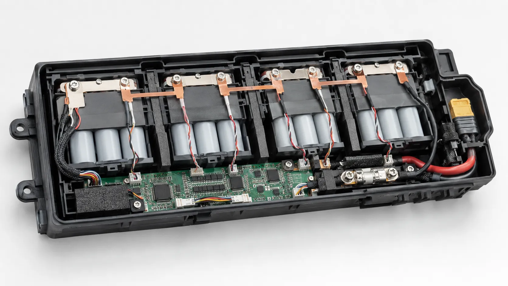
Direct answer: A 4S3P pack has four series-connected groups, each made from three parallel cells. Pack voltage is about four times cell voltage, while nominal capacity is about three times one cell. The BMS normally monitors four group voltages.
This architecture allows a single monitor channel to represent each group voltage, but it does not independently diagnose every cell in a parallel group. Production controls must therefore reduce the probability that one cell differs in model, capacity, resistance, self-discharge or weld quality.
| Architecture Layer | What Must Be Defined | Why It Matters |
|---|---|---|
| Cell model | Exact manufacturer, model, capacity, current, impedance and temperature limits | Parallel and series calculations are valid only for the approved cell. |
| Parallel group | Cell count, matching window, interconnect symmetry and cell-level fault strategy | Determines Ah, ideal current division, group resistance and available fault current. |
| Series stack | Group count, maximum/minimum voltage, insulation and sense wiring | Determines device voltage, charger, BMS channel count and balancing. |
| Main current path | Busbars, welds, wires, connectors, shunt, MOSFETs, contactor and fuse | Any element can become the voltage-drop or thermal limit. |
| Mechanical/thermal system | Cell support, spacing, vent path, sensor map and enclosure | Topology creates specific hot spots and propagation paths. |
| Validation and control | Final-device testing, BOM lock, traceability and revalidation rules | Ensures the production topology remains equivalent to the approved sample. |
7. How Series and Parallel Configuration Changes the BMS
Direct answer: Series count normally determines voltage-monitoring channels and balancing paths. Parallel count usually does not add voltage channels inside one permanent group, but it changes capacity, current range, fault current, heat load and protection requirements.
| BMS Area | Configuration Requirement | Customer Pain Point |
|---|---|---|
| Series voltage monitoring | One measurement channel per series group, with model-specific accuracy and threshold design | Total voltage can hide one weak group; broken sense wires and measurement errors require defined fault handling. |
| Balancing | Passive or active balancing across series groups | Balancing acts on group voltage/state; it cannot identify or repair one abnormal cell hidden inside a parallel group. |
| Current measurement | Shunt or Hall sensor range, direction and accuracy | Parallel count can raise load and fault current; regenerative or charging current may flow in both directions. |
| Over-current and short-circuit protection | Threshold, delay, MOSFET/contactor capability and fuse coordination | A printed current rating does not define interruption energy or temperature rise. |
| Temperature monitoring | Quantity and placement at cells, busbars, connector, MOSFETs or central pack region | More parallel cells can create internal hot spots that one outer sensor misses. |
| Precharge and contactors | Precharge resistance, sequence, weld detection and recovery rules | Important when connecting high-capacitance loads or parallel modules. |
| Communications and fault logging | CAN, SMBus, UART or custom messages; group voltages, current, temperature and isolation status | The device must understand whether a shutdown came from one weak series group, overload or a module connection fault. |
Analog Devices notes that cells can be arranged in series and parallel to meet voltage and capacity requirements, while small cell differences cause the weakest part of a stack to limit performance. TI battery-monitor documentation similarly treats balancing, voltage monitoring and protection as functions that must be adapted to the actual pack rather than copied from a reference circuit. For project-specific protection thresholds, NTC placement, fuse strategy, communication and wire routing, use THOR Power’s Connector, Wire & PCM/BMS Customization review before the sample drawing is approved.
Interconnection Resistance Can Defeat a Good Series-Parallel Calculation
A series-parallel pack is a network of electrochemical sources and resistive connections. Busbars, welds, screws, wires and connectors determine how current reaches each cell. A few milliohms of difference can redirect meaningful current in a high-power pack because current follows the lower-resistance path.
The layout should be reviewed for current-entry and current-exit symmetry. In some arrangements, the first cell or branch is physically closer to both terminals and therefore carries more current. Opposite-end takeoff, balanced busbar geometry or intentionally matched connection resistance may improve sharing, but the final design must be measured rather than assumed.
Representative Engineering Case 5: The Symmetric-Looking Parallel Group With Asymmetric Busbars
Project situation: A 4P cylindrical group used identical cells and equal-length holders. The main positive and negative pack leads were both attached near the same end of the group for convenient assembly.
Hidden risk: Cells nearest the takeoff points had a lower interconnection resistance and carried more current during repeated pulses. The pack-level current remained within target, but infrared and branch-current measurements showed local heating and unequal aging risk.
Engineering response: The busbar and takeoff geometry were redesigned to create a more balanced path. Weld quality, conductor thickness, voltage drop and branch temperature were validated under repeated pulses and low state of charge.
Buyer lesson: Visual symmetry does not prove electrical symmetry. Validate current distribution through the actual busbar, weld and lead arrangement.
Cell Matching Has Different Purposes in Series and Parallel
Series matching reduces the chance that one group reaches its voltage or capacity limit early. Parallel matching improves current sharing and reduces circulating current caused by resistance, capacity and state differences. The same exact cell model and controlled production lots are a starting point, not proof that all cells are identical.
| Matching Control | Why It Matters | Important Limitation |
|---|---|---|
| Open-circuit voltage | Helps prevent large equalization current during parallel assembly; identifies unusual storage state | Does not prove capacity or resistance match. |
| Internal resistance / impedance | Supports current-sharing and voltage-sag consistency | Measurement method, temperature and state of charge must be controlled. |
| Capacity | Reduces weak-group and end-of-discharge divergence | Capacity alone does not prove high-current capability. |
| Self-discharge / aging observation | Identifies cells that drift during storage | Requires time and controlled conditions; screening depth should match project risk. |
| Lot and model traceability | Reduces variation and supports failure analysis | A visually similar substitute is not equivalent without review. |
The 2014 study by Gogoana, Pinson and Bazant linked internal-resistance matching in parallel-connected lithium-ion cells to pack cycle-life impact. More recent physics-based analysis also shows that cell and interconnection resistance influence current imbalance and aging at module and pack level. For cylindrical-cell-specific insulation, welding, venting and replacement risks, continue to the 18650 Battery Safety guide.
Parallel Cells Are Not the Same as Parallel Finished Battery Packs
Cells permanently welded into one parallel group share a common group voltage and one BMS measurement point. Finished battery packs or modules may each contain their own BMS, fuse, contactor, state estimation and communication. Connecting these finished systems in parallel creates a higher-level power-sharing problem.
Module-level parallel operation must define voltage matching, state-of-charge matching, cable resistance, independent fusing, contactor sequence, precharge, fault isolation, communication, current limits and what happens if one module disconnects under load. A module that opens its BMS can suddenly transfer the full load to the remaining module.
| Parallel Level | Typical Architecture | Main Additional Risk |
|---|---|---|
| Permanent parallel cells in one group | Common electrical node inside one controlled pack | Cell matching, welds, fusible links, branch heat and hidden individual-cell faults |
| Parallel series strings inside one battery | Multiple complete strings feed one pack bus | String fusing, current sharing, BMS architecture and isolation of one failed string |
| Parallel finished modules | Each module may have independent BMS, fuse and contactor | Voltage/SOC matching, communication, precharge, load transfer and service procedures |
| User-added external battery | Added after product release or in the field | Unknown chemistry, age, charger, polarity and protection make uncontrolled paralleling unacceptable |
Precharge Is Often a Load-Connection Requirement, Not a Cell-Balancing Tool
A precharge circuit limits current when a battery connects to a load with large input capacitors, an inverter DC link or another energized bus. It may also be used in controlled module connection. The resistor, relay or contactor timing must be designed for the expected voltage difference, capacitance, energy and repetition rate.
Precharge should not be used to conceal a large or uncontrolled state-of-charge difference between battery modules. The connection procedure should first confirm voltage, polarity, health and communication. The control system must detect a failed precharge path or a welded main contactor before applying full power.
8. Series vs Parallel for Power: Why Higher Voltage Can Reduce Current
For the same electrical power, raising voltage reduces current according to P = V × I. Lower current can reduce I²R loss in the main conductors and connectors. This is one reason higher-voltage systems are used in power tools, robotics, mobility and industrial equipment. The benefit must be weighed against higher charger voltage, insulation, creepage, isolation, contactor and monitoring requirements.
| Example | Electrical Point | Ideal Power | Engineering Interpretation |
|---|---|---|---|
| Architecture A | 12 V at 30 A | 360 W | Higher current; larger conductor and connector demand |
| Architecture B | 24 V at 15 A | 360 W | Half the current for the same ideal power; approximately one-quarter of I²R loss in the same resistance |
| Architecture C | 48 V at 7.5 A | 360 W | Lower current again, but higher-voltage insulation, charger and BMS complexity |
The example is not a recommendation to maximize voltage. The device electronics, motor winding, regulatory category, user-access risk, connector and charging architecture must be designed for the chosen voltage. A DC/DC converter may also change the current drawn from the battery as voltage falls.
9. Six-Step Workflow for Choosing a Series-Parallel Configuration
Step 1: Define the Complete Voltage and Charging Window
Record the device minimum operating voltage, normal voltage, absolute maximum voltage, transient tolerance, shutdown behavior, charger output and any regenerative or adapter-related overvoltage. Use the exact cell minimum and maximum voltage rather than a 12 V, 18 V or 24 V marketing label.
Step 2: Measure the Load and Calculate Usable Energy
Capture standby, average, continuous, peak, inrush, stall and regenerative current at the battery terminals. Convert the runtime requirement into usable Wh with stated assumptions for conversion efficiency, cutoff, temperature, state-of-charge window and end-of-life margin.
Step 3: Select the Chemistry, Format and Exact Cell Model
Choose the chemistry, physical format and exact approved cell model before finalizing topology. Use the cell approval sheet for nominal and maximum voltage, discharge current, charge current, temperature range, impedance, life and safety limits.
Step 4: Determine Series and Parallel Count
Use the complete device and charging voltage window to determine Ns. Then use usable energy, continuous and peak current, derating, aging, thermal density, fault current and physical volume to determine Np. Recheck the full pack and ideal per-cell current calculations together.
Step 5: Engineer Protection, Current Paths and Mechanical Layout
Define BMS channels, balancing, NTCs, current thresholds, fuse coordination, contactors and precharge. Design busbars, welds, wires and connectors for resistance and heat, then confirm cell support, insulation, vent paths, sensor locations and service access.
Step 6: Validate the Final Device and Freeze the Production Configuration
Test voltage sag, usable runtime, branch current where required, hot spots, charger behavior, protection response, temperature extremes, vibration and aged-margin conditions in the final device. After approval, lock the cell model, topology, BMS, busbar, weld program, fuse, connector, wire, insulation, firmware and validation evidence. Use THOR Power’s battery capacity and runtime calculators for early energy estimates, then confirm topology with measured voltage and current data.
Already know your voltage window, load waveform and space limit? Get an engineering review of your series/parallel topology and current-sharing before you freeze the pack.
Talk to a Battery Engineer10. Thermal Management and Propagation Change With Topology
More cells in parallel can reduce ideal per-cell current, but the larger group may become denser and harder to cool. More cells in series increase the number of interconnections, sense wires and propagation pathways. The thermal design should be based on measured heat and failure consequences, not only nominal current per cell.
NREL thermal-management guidance emphasizes temperature uniformity, heat rejection and evaluation under realistic operating conditions. NASA high-power battery work also treats propagation resistance, venting and pack-level demonstration as design requirements rather than assumptions based on a single cell. For a broader explanation of internal faults, thermal runaway and pack-level propagation, review the Lithium-Ion Battery Safety guide.
| Topology-Driven Issue | Why It Matters | Engineering Response |
|---|---|---|
| Parallel density | Interior cells may be hotter than outer cells even when average current per cell is lower | Sensor map, spacing, heat spreading and repeated-pulse validation |
| Series interconnections | More busbar joints and sense points can create local resistance or wiring faults | Joining-process control, insulation, strain relief and sense-wire diagnostics |
| One cell failure in a parallel group | Healthy cells can feed current into the failed cell | Fusible links or controlled interconnect strategy according to risk |
| One group failure in a series stack | The full pack becomes unavailable and voltage redistributes across open components | BMS monitoring, fuse/contactor behavior and safe service procedures |
| Propagation path | Adjacent cells, busbars, enclosure and vent direction transmit heat and ejecta | Pack-level abnormal-condition and propagation evaluation where consequence requires it |
11. Common OEM Mistakes in Series and Parallel Battery Projects
Adding parallel cells to solve every current problem. More parallel cells cannot fix an undersized connector, weak weld, hot MOSFET, poor busbar or incompatible BMS threshold. Diagnose the complete current path first.
Using nominal voltage to select series count. A 12 V or 24 V label hides full-charge and cutoff behavior. Confirm the device minimum and maximum voltage before selecting chemistry and series count.
Assuming current divides equally in parallel. Cell and connection resistance, temperature and aging change branch current. Use a symmetric design and measure the finished pack.
Connecting modules in parallel without voltage matching. A small voltage difference can produce a large equalization current. Use a controlled connection sequence, precharge where applicable and independent protection.
Monitoring only total pack voltage. Total voltage can hide one weak or overcharged series group. Multi-series lithium packs normally require group-level monitoring.
Replacing one cell in an aged welded parallel group. A new cell may have different capacity, resistance and state behavior from aged neighbors. Field repair must follow an approved module or pack service strategy.
Treating a BMS current label as the pack rating. The pack current limit is set by cells, conductors, connector, MOSFETs, contactor, fuse, temperature and duty cycle together.
Changing parallel count without revalidating documentation. Topology changes can affect UN 38.3, safety reports, enclosure, charger, BMS and final-device approval scope.
Representative Engineering Case 6: The Field Repair That Replaced One Cell in a Welded Parallel Group
Project situation: A service team proposed replacing one failed cell inside an aged 4P group instead of replacing the complete module.
Hidden risk: The replacement cell had a different production date, resistance, capacity and state history. During high current, current sharing and aging would differ, while the repair process could damage adjacent insulation and welds.
Engineering response: The service strategy was changed to controlled module replacement or factory-authorized pack repair with cell-model verification, group rebuilding, matching, insulation inspection, joining validation and full electrical testing.
Buyer lesson: A single-cell replacement inside an aged welded group is not automatically equivalent to restoring the original pack.
12. How to Validate a Series-Parallel Battery Pack
A topology is not approved when the arithmetic is correct. Validation must confirm that the production-intent pack behaves correctly in the final product and that the BMS, charger, conductors, mechanical structure and thermal system remain within agreed limits.
| Validation Area | What to Measure | Acceptance Criteria Should Define |
|---|---|---|
| Voltage window | Full-charge voltage, group voltage, device undervoltage shutdown and BMS cutoff | Device stays within input limits; normal shutdown occurs before deep protection where intended. |
| Capacity and runtime | Usable Wh under representative load, temperature and end-of-life assumptions | Beginning- and end-of-life runtime targets and stated efficiency assumptions. |
| Continuous and peak current | Voltage sag, pulse duration, repeated pulses, stall and regenerative current | Cell, BMS, connector and conductor limits are met with temperature margin. |
| Parallel current sharing | Branch current or proxy measurements, interconnect voltage drop and cell temperature | No unacceptable branch imbalance or localized heating under worst-case duty. |
| BMS and balancing | Group measurement accuracy, balancing, sensor faults, protection delays and recovery | Every series group remains inside model-specific limits; recovery cannot repeatedly energize a persistent fault. |
| Thermal performance | Cells, internal group, busbars, BMS/MOSFETs, connector and enclosure hot spots | Temperature limits and uniformity are met at high ambient and with aged-resistance allowance. |
| Module paralleling | Voltage/SOC matching, precharge, contactor sequence, current sharing and module disconnect | No uncontrolled equalization, arcing or overload transfer to remaining modules. |
| Mechanical/environmental | Fit, vibration, drop, compression, insulation, moisture and service access | No latent cell, weld, sense-wire or connector damage. |
| Pilot production | Cell matching, weld program, polarity, sense wiring, final test and traceability | Production repeatability matches the approved sample and BOM. |
NASA validation guidance emphasizes integration and harmonization from cell to module, pack and final system. That principle is especially important for series-parallel batteries because the topology links cell behavior, interconnections, monitoring and device operation.
13. How Series-Parallel Changes Affect Certification and Transport Documents
Direct answer: Yes. Changing series count, parallel count, cell model, BMS, interconnections or enclosure can change the tested battery configuration. UN 38.3, IEC 62133-2 and IEC 62619 have different scopes, so report applicability must match the exact production model.
IEC 62133-2 applies to portable sealed secondary lithium cells and batteries within its scope. IEC 62619 covers secondary lithium cells and batteries for industrial applications, including stationary uses. UN Manual of Tests and Criteria, Sub-section 38.3, addresses transport testing for lithium cells and batteries. The final route still depends on the product category, market and exact configuration.
| Configuration Change | What Can Change | Buyer Reminder |
|---|---|---|
| Change cell model only | Current, voltage, safety behavior and report scope can change | Engineering review and possibly repeated testing/document updates |
| Increase parallel count | Capacity, energy, fault current, thermal density and pack dimensions change | Review BMS/current path, UN 38.3 model scope and pack-level safety evidence |
| Increase series count | Maximum voltage, BMS channels, charger, insulation and electrical category change | Re-evaluate device compatibility, protection, charger and applicable standards |
| Parallel finished modules | System fault current, precharge, contactors, communication and installation behavior change | Module and system-level validation; independent protection and isolation |
| Change interconnect or conductor | Current sharing, voltage drop and hot spots can change without changing nameplate ratings | Repeat current-path and thermal validation; update controlled BOM/process |
Review THOR Power’s battery certificates and compliance documents early, while confirming that the tested model, cell, topology, BMS and report holder match the production battery.
14. What an OEM Buyer Should Send Before Topology Selection
A supplier cannot responsibly choose series and parallel count from voltage, capacity and dimensions alone. The inquiry should describe the device and the conditions that determine voltage, energy, power and risk.
| Information Area | What to Provide | Why It Matters |
|---|---|---|
| Device voltage window | Minimum, normal, maximum and transient voltage; undervoltage behavior | Determines chemistry and series count. |
| Load waveform | Standby, average, continuous, peak, inrush, stall, regenerative current, pulse duration and duty cycle | Determines parallel count and the complete current path. |
| Runtime and life target | Runtime at beginning and end of life, recharge interval, cycles and storage period | Determines usable Wh, capacity margin and aging allowance. |
| Charging and power path | Adapter/USB/dock/solar input, charge current, operation while charging and backflow | Determines charger, BMS ports, precharge and firmware behavior. |
| Mechanical space | 3D envelope, cell orientation, wire exit, connector, heat sources, airflow and service access | Determines whether the topology can be built and cooled. |
| Environment | Temperature, humidity, vibration, installation and supervision | Affects cell limits, derating, matching and protection depth. |
| Compliance/logistics | Target market, product category, transport route, reports and volume forecast | Topology changes documentation, sample quantity and traceability. |
| Approval evidence | Required electrical, thermal, mechanical, device and pilot-production tests | Defines what must be proven before design freeze. |
15. What the Battery Supplier Should Return
| Supplier Output | Minimum Content | Why It Builds Trust |
|---|---|---|
| Recommended topology | Exact cell direction, Ns, Np, voltage window, Ah/Wh and known assumptions | Shows how series and parallel count were derived from the device. |
| Current and runtime basis | Continuous/peak current, per-cell estimate, usable energy, efficiency and aging assumptions | Makes performance claims reviewable. |
| BMS/protection concept | Series channels, balancing, NTCs, thresholds, fuse/contactors, precharge and communications | Explains how the topology is monitored and isolated. |
| Interconnection proposal | Busbar/weld approach, wire, connector, symmetry, voltage drop and temperature-rise plan | Addresses real current sharing rather than arithmetic only. |
| Mechanical/thermal proposal | Dimensions, support, spacing, vent path, sensor map and enclosure interface | Prevents density and topology from creating hidden hot spots. |
| Validation plan | Voltage, runtime, current sharing, thermal, protection, module connection and pilot tests | Defines evidence for sample approval and design freeze. |
| Controlled items | Cell, topology, BMS, fuse, busbar, weld program, connector, wire, firmware and process | Protects the production pack from undocumented substitutions. |
16. How THOR Power Supports Series-Parallel Battery Pack Engineering
THOR Power supports custom LiPo pouch batteries, lithium-ion battery packs, 18650 / 21700 packs, LiFePO4 backup and energy-storage batteries and custom special battery packs. The topology review begins with device voltage, load waveform, runtime, charger, environment and risk rather than a preferred cell count.
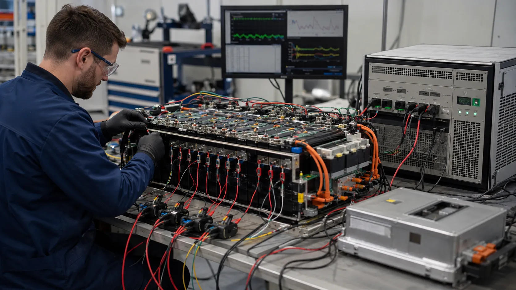
The engineering process can include chemistry and cell-model screening, series and parallel calculation, current-path review, PCM/BMS and fuse matching, connector and wire selection, precharge or contactor logic, mechanical and thermal review, prototype development, final-device testing, documentation planning and mass-production change control.
Production quality controls can include cell appearance and lot review, open-circuit-voltage and internal-resistance checks, capacity verification according to project requirements, cell matching, weld or joining inspection, sense-wire and polarity checks, PCM/BMS function testing, charge-discharge validation, aging and final electrical inspection. A controlled battery pack production process should preserve the approved topology, cell lots, joining parameters, protection settings and traceability from sample to long-term supply.
17. When to Involve THOR Power
The best time to involve a battery engineer is before the device voltage window, charger, enclosure, connector and certification route are frozen. Early review makes it possible to compare voltage, current, runtime, size, cost and risk without forcing a late redesign. If the product already has a prototype, provide the battery voltage at startup and shutdown, measured current waveform, runtime, charger details, enclosure drawing, target market and observed problems. You can also start from a full custom battery engineering review.
If the product already has a prototype, provide the battery voltage at startup and shutdown, measured current waveform, runtime, charger details, enclosure drawing, target market and observed problems.
18. Key Takeaways for OEM and ODM Buyers
- Series increases the battery voltage; parallel increases ampere-hour capacity and ideal current capability at the same voltage.
- The full charge-to-cutoff voltage window, not the nominal label, determines the correct series count.
- Parallel current does not divide perfectly. Cell resistance, welds, busbars, temperature and aging influence each branch.
- A 4S3P pack contains four monitored series groups, each made from three parallel cells; the BMS normally does not see twelve independent cell voltages.
- The weakest series group limits usable pack energy, while a failed cell in a parallel group may receive fault current from its neighbors.
- Adding parallel cells cannot repair an undersized connector, hot MOSFET, poor busbar or incorrect protection threshold.
- Parallel modules require voltage and state-of-charge matching, independent protection, connection sequencing and precharge where the system needs it.
- Cell matching, current-path symmetry, temperature sensing and group-level monitoring are production controls, not optional refinements.
- Topology changes can affect charger compatibility, BMS channels, fault energy, thermal design, UN 38.3 and safety certification scope.
- The correct series-parallel battery is validated in the final device and remains controlled from approved sample to mass production.
19. Conclusion
Series and parallel connections are the foundation of battery-pack architecture, but they are not a shortcut around application engineering. Series count defines the voltage window and monitoring structure. Parallel count defines nominal capacity and helps provide current, while also increasing fault current and current-sharing complexity. The finished pack behaves according to the weakest series group, the lowest-resistance parallel path and the hottest component in the complete system.
For OEM teams, the best design process is to measure the real device first. Define the maximum and minimum voltage, current waveform, runtime, charger, enclosure, temperature, service model and certification route. Then select the exact cell and calculate a topology that can be protected, cooled, manufactured and validated with adequate margin. THOR Power supports this process across pouch, cylindrical, prismatic, LiFePO4 and custom special battery-pack projects.
Planning a Custom Series-Parallel Battery Pack?
Send your device voltage window, load waveform, runtime, peak current, battery space and charger. THOR Power can derive the series/parallel topology, BMS and current-path design, then deliver samples with UN38.3/MSDS support and stable mass production.
Talk to a Battery Engineer20. FAQ: Series vs Parallel Battery Configuration
FAQ: Series vs Parallel Battery Configuration
What is the main difference between batteries in series and parallel?
Series-connected cells increase voltage while keeping ampere-hour capacity approximately equal to one parallel group. Parallel-connected cells keep the same voltage while increasing ampere-hour capacity and ideal current capability. Real designs must also consider voltage limits, current sharing, fault current, BMS and thermal behavior.
Does connecting batteries in series increase capacity?
It increases watt-hour energy because the voltage rises, but the ampere-hour capacity remains approximately that of one parallel group. For example, four identical 3 Ah cells in series form a 4S1P pack with approximately 3 Ah at four times the cell voltage.
Does connecting batteries in parallel increase current?
Parallel cells can provide more current because the load is shared, but ratings are not perfectly additive. Cell resistance, interconnection resistance, temperature, aging, busbars, BMS and connectors can limit the finished pack.
How does a 4S3P battery pack work?
Three cells are connected in parallel to form one group, and four of those groups are connected in series. The pack voltage is approximately four times the cell voltage, while nominal ampere-hour capacity is approximately three times the cell capacity. The BMS normally monitors four group voltages.
Can lithium batteries be connected in parallel at different states of charge?
They should not be directly connected without a controlled procedure. A voltage difference can drive a large equalization current that damages connectors, BMS switches or contactors. Match voltage and state of charge, verify polarity and use current-limited connection or precharge where the system requires it.
Why does one weak series group reduce the runtime of the whole battery?
The weak group reaches the upper or lower voltage limit first. The BMS must stop charging or discharging to protect that group even when the other groups still contain energy.
Do cells connected in parallel need balancing?
Permanently parallel cells share a common voltage and tend to equalize, so a BMS usually balances between series groups rather than between cells inside one permanent parallel group. However, parallel cells still require matching, symmetric interconnections and fault control because individual current and health can differ.
Can I add more parallel cells to stop a BMS from tripping?
Only after identifying the real limit. More parallel cells may reduce ideal per-cell current, but the trip may be caused by an incorrect threshold, MOSFET heating, connector resistance, weak weld, undersized wire or motor stall.
Can two finished battery packs be connected in parallel?
Only when both packs and the system are specifically designed for parallel operation. Confirm chemistry, series count, voltage, state of charge, BMS behavior, independent fusing, cable resistance, contactor sequence, precharge, communication and load transfer if one pack disconnects.
Can protected battery packs be connected in series?
Not automatically. The BMS, charger, communications, insulation and recovery behavior may not support series stacking. One pack can disconnect and expose another pack or the device to an unexpected voltage. Use a battery architecture specifically designed and validated for the required series voltage.
How should an OEM choose the number of cells in parallel?
Calculate usable energy and the continuous/peak current using the exact cell model, then include temperature, aging, current sharing, fault energy, physical volume and production margin. Validate the proposed parallel count in the final device.
Does changing series or parallel count affect UN 38.3 or certification?
It can. Topology changes alter voltage, capacity, energy, BMS, enclosure and fault behavior. Confirm whether the new configuration is covered by the existing test report and whether pack or end-product testing must be repeated.
21. References
- NASA. Guidelines on Lithium-Ion Battery Use in Space Applications.
- NREL. Integration Issues of Cells into Battery Packs.
- NREL. An Approach for Designing Thermal Management Systems for Electric and Hybrid Vehicle Battery Packs.
- Texas Instruments. Battery Cell Balancing: What to Balance and How.
- Texas Instruments. Cell Balancing With BQ769x2 Battery Monitors.
- Analog Devices. Battery Stack Monitor Maximizes Performance of Li-Ion Batteries.
- Gogoana, Pinson, Bazant & Sarma. Internal Resistance Matching for Parallel-Connected Lithium-Ion Cells and Impacts on Battery Pack Cycle Life (J. Power Sources, 2014).
- DOE / OSTI. Physics-Based Analysis of Cell Imbalances and Aging in Lithium-Ion Battery Modules and Packs.
- DOE / OSTI. Impact of Module Configuration on Lithium-Ion Battery Current Sharing and Aging.
- NASA. Driving Design Factors for Safe, High-Power Batteries for Space Applications.
- NASA. New Li-Ion Technology Trends and Validation Process.
- International Electrotechnical Commission. IEC 62133-2:2017+A1:2021.
- International Electrotechnical Commission. IEC 62619:2022.
- UNECE. UN Manual of Tests and Criteria, Revision 8 (Sub-section 38.3).
Case Transparency Note
The engineering cases in this article are representative composite scenarios built from recurring battery-project patterns. They explain design decisions without identifying a customer or presenting confidential project data as a published THOR Power case study.



Dr. Maximilian Weber is THOR Power's Chief Scientist and a senior expert in lithium battery technology. His technical review focuses on battery safety, performance optimization, energy density and custom battery solution development.
Last technical review: September 2026

Victor Xiong holds a Master's degree from The Chinese University of Hong Kong, Shenzhen. He leads THOR Power's OEM Division and focuses on custom battery solutions for global device brands, product developers and industrial customers.