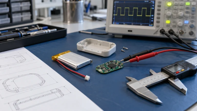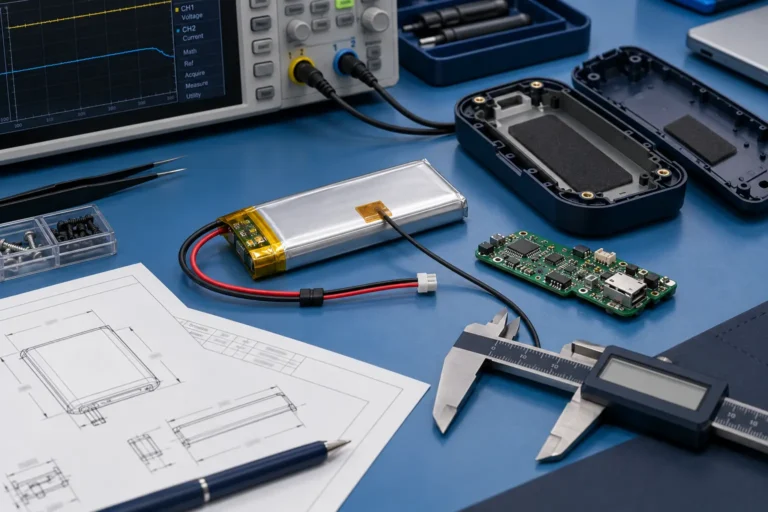
Custom LiPo Battery Size Guide: How to Specify Pouch Cell Dimensions for OEM Products

Technically Reviewed By
Chief Scientist
Dr. Maximilian Weber is THOR Power’s Chief Scientist and a senior expert in lithium battery technology. His technical review focuses on battery safety, performance optimization, energy density and custom battery solution development.
Last technical review: September 2026

Written By
President of OEM Division & Custom Battery Specialist
Victor Xiong holds a Master’s degree from The Chinese University of Hong Kong, Shenzhen. He leads THOR Power’s OEM Division and focuses on custom battery solutions for global device brands, product developers and industrial customers.
| Written By | Technically Reviewed By |
|---|---|
| Victor Xiong President of OEM Division & Custom Battery Specialist. Victor Xiong leads THOR Power OEM battery development for global device brands, product developers and industrial customers. | Dr. Maximilian Weber Chief Scientist. Dr. Weber reviewed this article for pouch-cell geometry, finished-pack fit, mechanical clearance, protection-board integration, connector and wire routing, RFQ completeness and production release control. |
Quick Answer
A custom LiPo battery size should be specified from the finished battery envelope that the device can accept, not from a pouch-cell code alone. Start with maximum finished thickness, width and length, then account for edge seals, tab area, PCM, insulation, wire exit, connector, NTC, assembly tolerance and project-defined mechanical clearance before approving the cell geometry.
Four Approval Questions
1. Does the drawing define the maximum finished battery size, not only the bare-cell code? 2. Is there positive clearance for thickness, edge seals, PCM, wires, connector and bend radius? 3. Does the chosen geometry still meet runtime, peak load, charge and temperature requirements? 4. Can production repeat the approved finished-pack envelope and inspection method?
Table of Contents
- 1. Start With the Finished Battery Envelope
- 2. Read LiPo Size Codes as Search Clues Not Drawings
- 3. Protect Thickness Before Chasing Capacity
- 4. Use Available Width and Length Before Consuming Critical Z Height
- 5. Estimate Capacity From Usable Volume and Load Requirement
- 6. Approve PCM Wires Connector and NTC as Part of the Size
- 7. Choose Standard or Flexible Size LiPo Cells
- 8. Match Geometry to Medical Handheld IoT and Compact Devices
- 9. Send an RFQ That Lets Engineering Solve the Fit
- 10. Key Takeaways
1. Start With the Finished Battery Envelope
Most battery-sizing problems start when a buyer chooses a cell drawing before defining the device cavity. The safer sequence is the reverse: define the maximum finished battery envelope the product can accept, including wire route and connector location, then work backward to the pouch-cell body.
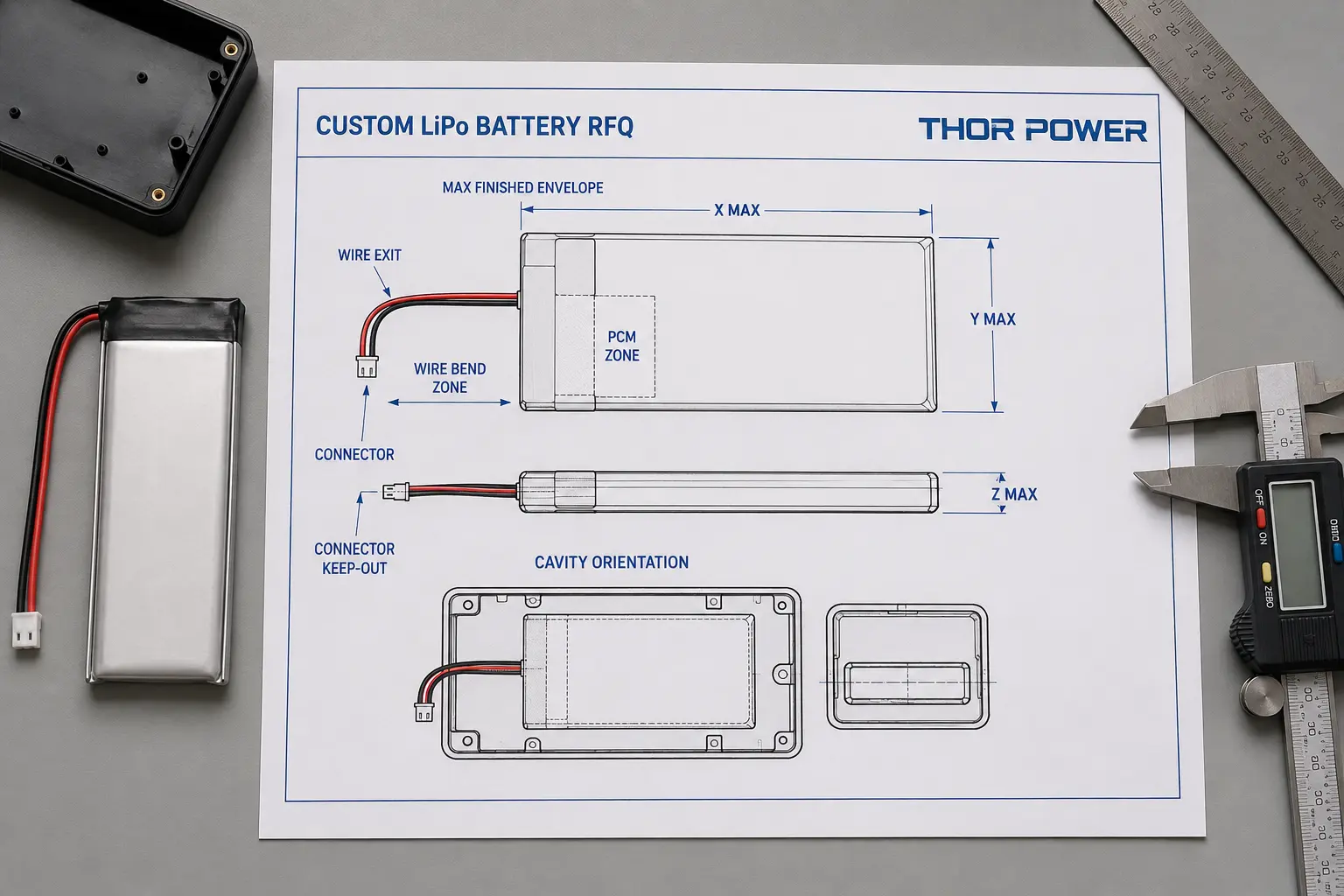
Useful inputs are maximum finished thickness, width and length; preferred wire-exit side; battery connector selection and keep-out zone; cable bend radius; nearby heat sources; compression points; and whether the pack is removable or permanently installed. This is where custom LiPo battery size becomes an engineering limit, not a catalog preference.
For initial dimension matching, review THOR Power custom LiPo battery options and compare the closest standard pouch-cell geometries before requesting a new cell size.
Size rule: Never treat bare-cell dimensions as finished battery dimensions. A 6 x 40 x 60 mm pouch cell does not remain 6 x 40 x 60 mm after protection, insulation, lead wires and connector are added.
2. Read LiPo Size Codes as Search Clues Not Drawings
LiPo pouch cells are often described by compact model codes that approximate thickness, width and length. A code such as 603040 is commonly read as a cell around 6 mm thick, 30 mm wide and 40 mm long. That code is useful for early search, but it is not a released mechanical drawing.
Production cells may include tolerance, top seal, side seal, tab area and supplier-specific measuring conventions. The finished LiPo pouch battery can then grow again because of PCM placement, insulation tape, NTC, wire routing and connector geometry. Keep three values separate: nominal code, controlled bare-cell maximum and controlled finished-pack maximum.
Finished Battery Dimension Budget
Convert the device cavity into a releaseable battery envelope before selecting the bare cell. The allowance is project-specific; do not assume a universal 0.5 mm or 1 mm clearance.
| Dimension / feature | Device-side input | Finished-pack release control | Bare-cell design implication |
|---|---|---|---|
| Thickness (Z) | Cavity depth, local obstructions, enclosure rigidity | Maximum finished thickness plus project-defined clearance | Do not select nominal cell thickness equal to the full cavity depth. |
| Width (X) | Side walls, rails, adhesive zone, edge keep-out | Maximum finished width including seals, wrap and local stack-up | Leave room for side seals and assembly tolerance. |
| Length (Y) | End walls, top-seal zone, PCM and connector space | Maximum finished length and any controlled local projection | Reserve space for top seal, tabs and protection-board placement. |
| Wire exit | Routing side, bend zone and moving/hinged parts | Exit direction, gauge, length and minimum routing space | Do not consume the remaining cavity with a late harness change. |
| Connector | Mating access and connector keep-out zone | Exact housing, pinout, mating part and local protrusion | The connector can exceed the pouch-body envelope even when the cell fits. |
Release rule: The battery drawing should control the maximum finished envelope and inspection method. Mechanical clearance should be defined from production pack tolerance, enclosure design, expected dimensional change over life, temperature and the project risk assessment – not from nominal cell dimensions alone.
3. Protect Thickness Before Chasing Capacity
Thickness is usually the least forgiving dimension in compact electronics. A pouch cell may sit between a PCB and housing wall, under a display, behind a sensor module or inside a sealed handheld shell. A small Z-height error can create pressure, deformation, assembly yield loss or field returns.
If the available battery cavity is 6.5 mm deep, selecting a cell with a nominal 6.5 mm thickness leaves no defined allowance for cell tolerance, insulation, local PCM stack-up or mechanical clearance. Unless the enclosure and production drawing explicitly accommodate that stack-up, it is generally not a robust release condition. A pouch cell should not rely on the enclosure to compress it into specification.
4. Use Available Width and Length Before Consuming Critical Z Height
When a buyer wants more capacity, the first request is often a thicker cell. When the cavity allows it, increasing usable width or length may be preferable to consuming additional Z-height. Extra thickness can use the most sensitive mechanical margin immediately, while a wider or longer footprint may add active area without creating the same local stack-up pressure.
The best geometry depends on the real cavity. A long narrow pouch may suit a handheld instrument; a short wide pouch may fit a wearable module; a larger flat cell may use space under a display more efficiently. Width or length is not automatically better than thickness: PCB edges, connector zones, structural support, tab placement and power requirements can change the trade-off. For custom LiPo projects, define the dimension priority order before asking for more mAh.
5. Estimate Capacity From Usable Volume and Load Requirement
Capacity generally rises with usable electrochemical volume, but there is no universal conversion from cubic centimeters to mAh. Chemistry, electrode loading, separator, electrolyte, tab design, safety margin and power capability all affect final capacity. This is why a high capacity LiPo battery cannot be selected by dimensions alone.
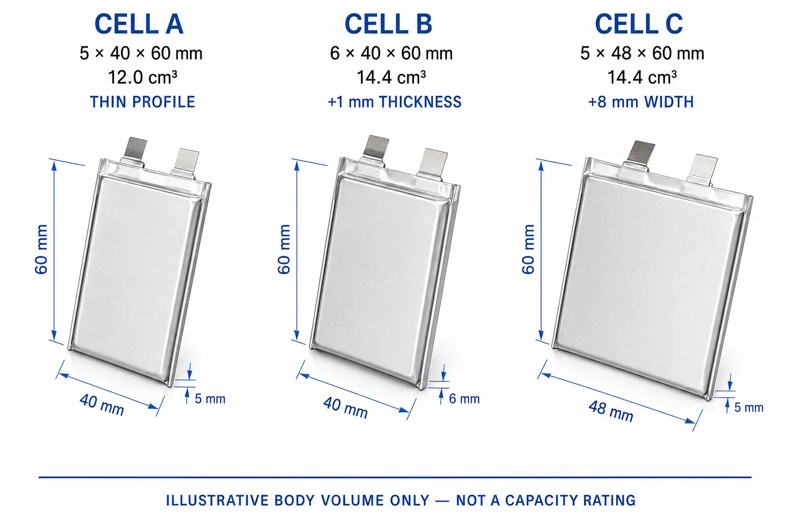
Illustrative Volume Trade Off
- Cell A: 5 x 40 x 60 mm, 12.0 cm3. Thin profile; may suit tight Z-height.
- Cell B: 6 x 40 x 60 mm, 14.4 cm3. More nominal body volume, but consumes 1 mm more thickness.
- Cell C: 5 x 48 x 60 mm, 14.4 cm3. Same nominal volume as B, achieved through width rather than thickness.
Illustrative calculation only. These body-volume numbers do not predict a specific THOR Power capacity and do not include seals, tabs, PCM or pack assembly.
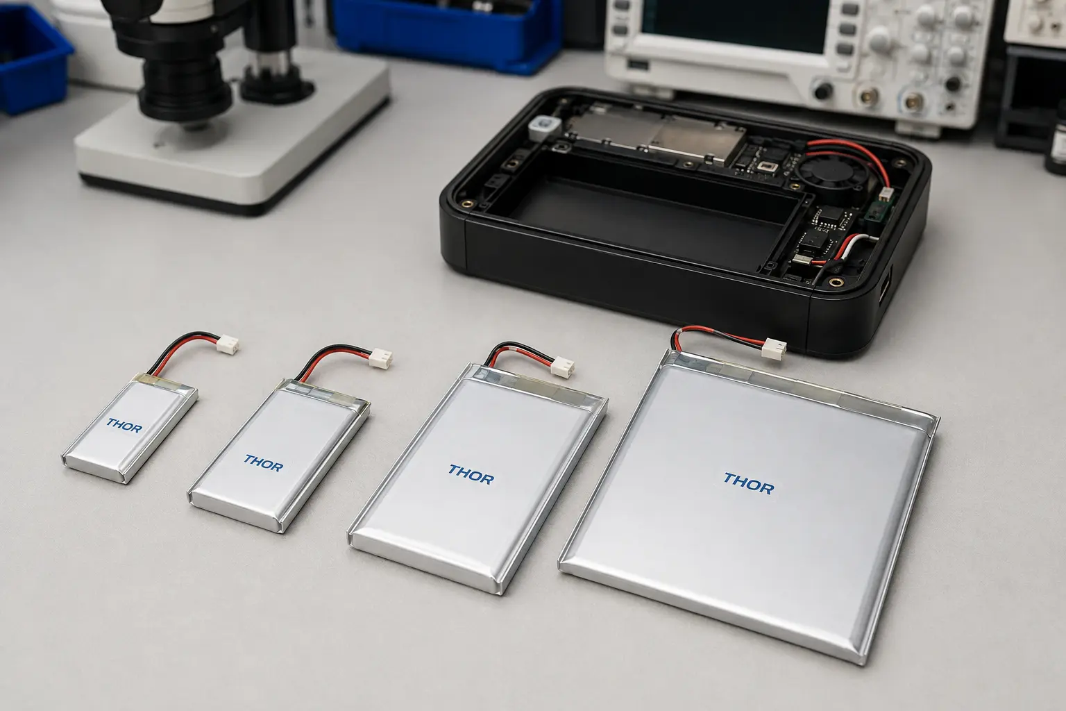
6. Approve PCM Wires Connector and NTC as Part of the Size
A bare LiPo pouch battery is only one part of the finished pack. The released drawing should include the pouch body, edge seals, tab area, PCM or protection board, insulation, label, lead wires, connector, NTC and the required bend or exit zone.
For the pack-interface stack-up, see THOR Power's battery connector, wire gauge and NTC selection guide.
- PCM / protection PCB: May add length, width or local thickness. Define protection function, board location and maximum finished size.
- Insulation / tape / sleeve: Adds a small but real stack-up around the cell. Define maximum finished dimensions after assembly.
- Lead wires: Require exit space and bend radius. Define wire gauge, length, exit direction and routing.
- Connector: Can become the largest local feature outside the pouch body. Define housing, pitch, pinout and mating connector.
- NTC / sensing: Adds wiring and placement constraints. Define NTC type, location and connector pin assignment.
Many custom projects fail when a buyer approves a cell sample first and adds a different connector or longer harness later. The added components consume the remaining space even though the cell itself has not changed.
7. Choose Standard or Flexible Size LiPo Cells
A standard catalog cell is usually the fastest starting point when its bare-cell dimensions already fit the device with adequate finished-pack margin. It simplifies sampling, comparison and future supply.
When working with a LiPo battery manufacturer that supports flexible pouch-cell sizes, customization becomes valuable when the product has an unusual cavity, one dimension is tightly constrained, available footprint is being wasted or the application needs a capacity-and-power balance that standard LiPo pouch cells cannot provide. Custom should mean controlled geometry with a real device-level benefit, not a new size for its own sake.
8. Match Geometry to Medical Handheld IoT and Compact Devices
Different OEM products fail for different mechanical reasons. A medical monitor may need controlled traceability and connector consistency. A rugged handheld terminal may need long runtime, drop-resistant routing and a protected wire exit. A smart sensor may need thin packaging plus stable voltage under wireless bursts.
For buyers sourcing a custom pouch lithium battery for a medical device, the useful RFQ is not only capacity and voltage. It should include controlled cavity drawings, maximum finished-pack dimensions, connector requirements, traceability expectations and validation conditions.
- Medical / portable instruments: controlled finished envelope and reproducible assembly. Common mistake: asking for a medical pouch cell without a controlled cavity drawing.
- Handheld terminals: runtime, connector robustness and wire routing. Common mistake: selecting capacity first, then discovering the connector path blocks assembly.
- Smart devices / IoT: thin enclosure plus wireless peak-load margin. Common mistake: ignoring voltage sag while optimizing only mAh.
- Wearables / compact modules: finished thickness, edge clearance and local pressure control. Common mistake: choosing by nominal code without checking pack stack-up.
Compliance boundary: Battery-level safety and transport requirements such as IEC 62133-2 and UN 38.3 address their own scopes; satisfying them does not by itself certify the finished medical device. Define the applicable cell, battery and device requirements for the target product and market [1,2].
For smart devices with wireless or motor peak loads, mechanical fit should be checked together with the LiPo battery voltage sag guide so added capacity does not hide a peak-load voltage-margin problem.
9. Send an RFQ That Lets Engineering Solve the Fit
A good RFQ lets the battery supplier solve the packaging problem before sample tooling or assembly begins. Send more than a target capacity.
- Maximum finished battery thickness x width x length.
- Cavity drawing, photo or CAD screenshot with battery orientation.
- Target nominal voltage and runtime or capacity.
- Typical current, peak current and peak duration when relevant.
- Connector, pinout, wire gauge, wire length and exit direction.
- PCM/protection requirements and NTC requirement.
- Charging method and maximum charge voltage.
- Operating temperature range and nearby heat source.
- Expected sample quantity and forecast production quantity.
- Whether a standard cell is acceptable or custom geometry is required.
If the runtime target is still being converted into required capacity, use the battery capacity and runtime calculation guide before locking the mechanical envelope.
Buyer-side check: If the cavity drawing shows only the cell body and not the connector, wire route and protection-board zone, the RFQ is not mechanically complete.
Planning a Custom LiPo Battery Pack?
Share your maximum finished battery envelope or cavity drawing, thickness limit, runtime target, peak current, connector, wire length and charging method. THOR Power can compare standard LiPo pouch cells first, then recommend a flexible-size custom pack only when it improves real device fit, runtime or production stability.
10. Key Takeaways
- Specify the maximum finished battery envelope first.
- Keep nominal code, bare-cell maximum and finished-pack maximum separate.
- Protect thickness margin before chasing more mAh.
- When the cavity permits, use available width or length before consuming critical Z-height.
- Do not treat dimensions as a fixed capacity formula.
- Include PCM, insulation, wires, connector and NTC before fit approval.
- Use standard pouch cells when they fit; use flexible-size geometry only when it creates a real device-level advantage.
Conclusion
Custom LiPo battery sizing is a packaging-and-performance decision, not a catalog lookup. The reliable process starts from the finished device cavity, separates nominal code, bare-cell maximum and finished-pack maximum, and then optimizes capacity inside a controlled mechanical margin.
For THOR Power projects, send the maximum finished battery size, cavity orientation, runtime target, load profile, connector, wire and protection requirements. The engineering team can compare standard LiPo pouch battery options first and evaluate a flexible-size custom cell only when the geometry or performance target justifies it.
FAQ: Custom LiPo Battery Size
What does a LiPo battery size code such as 603040 mean?
It is a nominal shorthand for thickness, width and length. It should not replace the supplier controlled drawing because seals, tabs, tolerance and finished-pack components can change the real envelope.
Can I use the cavity size as the bare-cell size?
Usually no. The finished pack needs allowance for protection, insulation, wire exit, connector, assembly tolerance and mechanical clearance.
Does a thicker LiPo always give more capacity?
More active volume can support more capacity, but thickness is only one direction. A wider or longer cell may use available space more safely, and capacity also depends on chemistry and cell design.
What is the difference between a LiPo pouch cell and a finished LiPo battery pack?
The pouch cell is the electrochemical cell body. A finished pack may add PCM or BMS, insulation, wires, connector, NTC, labels and other assembly features.
When should I work with a LiPo manufacturer that supports flexible pouch-cell sizes?
Use this type of supplier when standard cells cannot use the cavity efficiently, one dimension is tightly constrained or the required capacity-and-power balance cannot be achieved with practical standard geometries.
What should I send to get a custom LiPo size recommendation?
Send maximum finished dimensions, a cavity drawing, voltage and runtime target, load profile, connector and wire details, protection and NTC needs, charging method, temperature range and expected quantity.
How much clearance should I leave around a LiPo pouch battery?
There is no universal clearance value. Required clearance depends on the controlled maximum finished-pack dimensions, cell and assembly tolerance, insulation, local PCM or connector stack-up, enclosure rigidity, expected dimensional change over life, temperature and the product's mechanical risk assessment. Define clearance from the finished production pack, not from nominal cell dimensions.
Technical References
Reference scope note: These references support the safety/transport boundary discussed in Section 8. They do not define a universal mechanical clearance, a fixed capacity-per-volume conversion or a medical-device certification.
- International Electrotechnical Commission. IEC 62133-2:2017+AMD1:2021, Safety requirements for portable sealed secondary lithium cells and batteries.
- UNECE. Manual of Tests and Criteria, Revision 8, Subsection 38.3, lithium battery transport testing.