High-Discharge LiPo Battery: How to Validate Continuous, Peak and Pulse Current

Written by Victor Xiong
President of OEM Division and Custom Battery Specialist at THOR Power, focused on defining cell, pack, device-integration and production requirements for OEM battery programs.

Technically reviewed by Dr. Maximilian Weber
Chief Scientist at THOR Power. Review focus: dynamic battery response, continuous and pulse-current validation, voltage margin, protection behavior and production release.
An OEM engineering guide to load waveforms, voltage sag, protection limits and production validation
A high discharge LiPo battery is not defined by one universal C rate. For an OEM device, it is a specific cell and finished pack that can deliver a defined continuous or pulse load while the device stays above its minimum input voltage and the battery remains within its electrical, thermal, protection and life limits.
The engineering requirement is therefore the load waveform and the complete path from cell to PCB. A statement such as “3C pulse” or “2A peak” is incomplete unless it also defines duration, repetition, state of charge, temperature, minimum acceptable voltage and the point at which current and voltage are measured.
Quick Answer
To validate a high discharge LiPo battery, first record the real device current waveform. Then test the production-intent cell, PCM, wires and connector while measuring both pack-output voltage and PCB-input voltage. Repeat the critical load at the lowest relevant state of charge, minimum operating temperature and aged condition. Release continuous and pulse limits separately, with explicit pass or fail criteria.
Every current requirement should include:
- Current in amperes at a stated measurement point.
- Continuous duration or pulse width.
- Pulse repetition, duty cycle and rest time.
- Minimum state of charge and operating temperature.
- Minimum permitted pack voltage and PCB input voltage.
- The exact cell, PCM, wire, connector and host interface used for validation.
Table of contents
- Start With the Actual Load Waveform
- Establish the Cell, Pack and PCB Measurement Boundaries
- Measure Voltage Sag and Find Where the Margin Is Lost
- Check the Protection Circuit and Repeated Pulse Heating
- Worked Example for a 600mAh Pack
- Validate Production-Intent Samples
- Prepare an Engineering RFQ
- Engineering Decision
- FAQ: High-Discharge LiPo Battery Current
- Technical References
1 Start With the Actual Load Waveform
Portable electronics often fail during a short event rather than during the average load. Radio transmit bursts, motor or pump startup, haptic actuators, camera or flash events, heaters and processor-intensive states can demand several times the idle current. The battery must support the event long enough for the device to complete it without brownout, protection shutdown or excessive heat.
Use C rate only to convert a capacity-normalized request into amperes. The arithmetic is useful, but it does not prove that a particular cell construction or finished pack can supply that current. For basic definitions and conversion examples, see the LiPo battery C rate guide. This article focuses on how to verify the resulting current requirement in the finished device path.
| Requirement field | Why it matters | Production-ready release format |
|---|---|---|
| Continuous load | Sets sustained voltage and thermal demand | Current in A, required duration or steady-state criterion, SOC, temperature and cutoff |
| Pulse load | Sets transient voltage and protection demand | Current in A, pulse width, repetition, rest time, SOC, temperature and minimum voltage |
| Measurement boundary | Prevents cell, pack and PCB values from being mixed | State whether the value applies at the bare cell, pack output or PCB input |
| Device limit | Defines the actual functional pass condition | Brownout or reset threshold plus the project engineering margin |
Do not release “peak current” as a standalone number. A two-second startup pulse and a millisecond radio burst can create different cell polarization, PCM behavior and voltage response even when their current amplitude is the same.
2 Establish the Cell Pack and PCB Measurement Boundaries
A cell rating is not automatically a finished-pack rating. The pack adds tabs or welds, protection MOSFETs, PCB copper, wires, crimps and a connector. The host product adds the mating connector, board traces, input capacitors and the regulator. Each layer can become the limiting element.
| Boundary | What is included | Typical evidence |
|---|---|---|
| Bare cell | Cell electrochemistry, tabs and internal current collectors | Cell terminal voltage, current, surface temperature and recovery |
| Finished pack output | Cell plus welds, PCM, FETs, wires and battery connector | Pack voltage, protection action, harness temperature and recovery |
| Device PCB input | Finished pack plus mating connector, PCB path and input stage | Minimum PCB voltage, reset status and regulator response |
For a device-level release, the practical current limit cannot exceed the lowest validated capability in the complete path. A cell can pass while the PCM trips. A finished pack can pass at its connector while the device still resets because the mating connector, board trace or regulator consumes the remaining voltage margin.
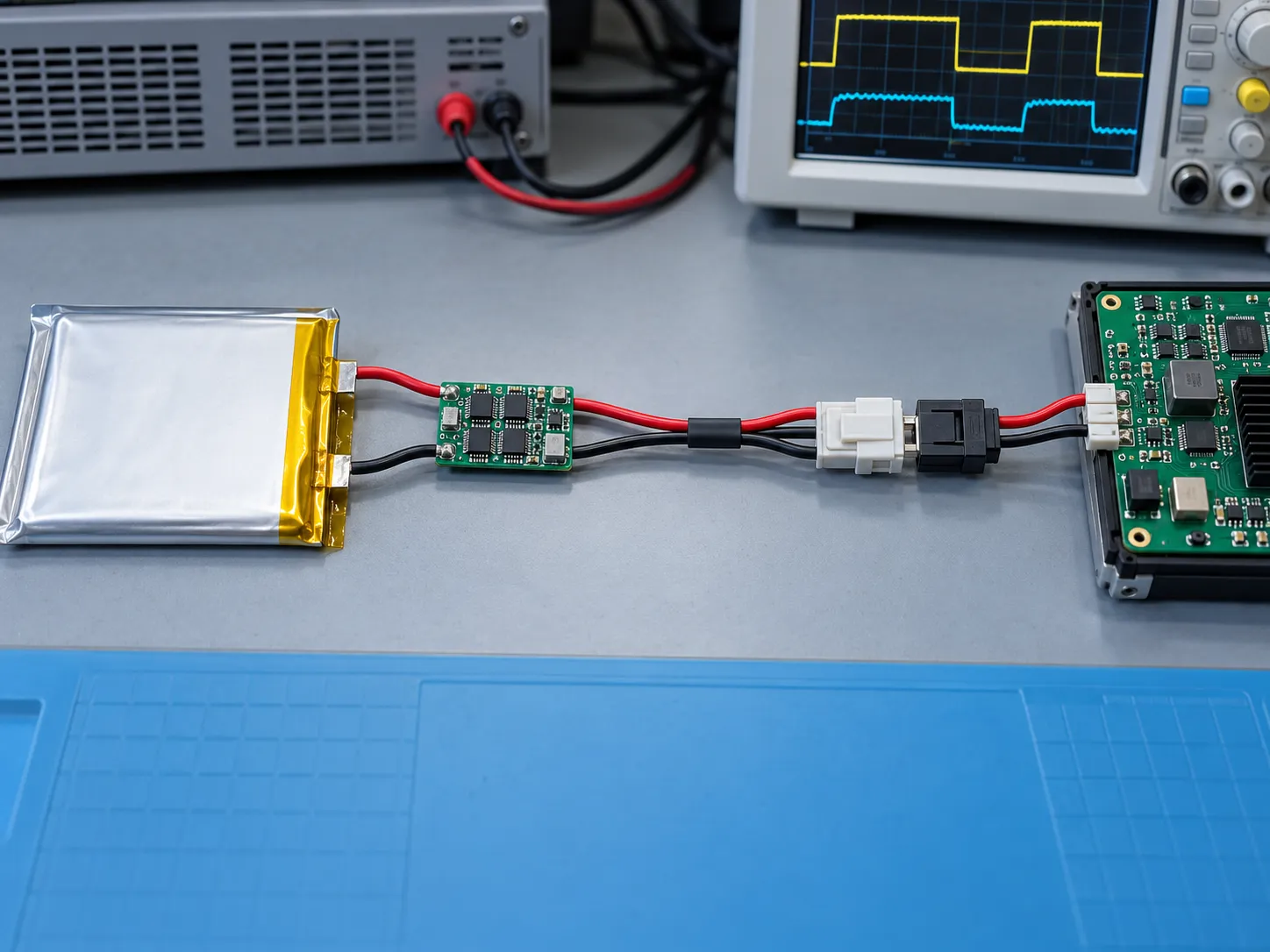
During a critical pulse, record current and voltage simultaneously. Measure at the pack output and, when practical, at the PCB input. The difference between pack-output and PCB-input voltage exposes losses in the mating connector, device-side contact and PCB input path. To locate losses inside the battery pack, compare cell-terminal voltage with pack-output voltage; that comparison captures weld, PCM/FET, pack-wire and battery-side connector losses. Select oscilloscope bandwidth and sample rate according to the shortest event that the product must survive; a slow logger can miss the true minimum voltage.
3 Measure Voltage Sag and Find Where the Margin Is Lost
Many apparent capacity failures are actually voltage-margin failures. When current rises, the cell terminal voltage drops because of immediate ohmic loss and time-dependent electrochemical polarization. The PCM, welds, wires, connector and PCB add further loss.
VPCB,min ≈ Vcell,pre - DeltaVcell,dynamic - DeltaVpack-path - DeltaVhost-interfaceVcell,pre is the cell-terminal voltage immediately before the pulse. DeltaVpack-path includes welds, PCM/FETs, pack wire and the battery-side connector; DeltaVhost-interface includes the mating connector and PCB input path. Use all terms from the same pulse width, SOC, temperature and aging condition, and do not subtract any path element twice.
The dynamic cell term is not a universal fixed resistance. Lithium-ion resistance depends on SOC, temperature, state of health and the measurement timescale. A resistance value derived from a long pulse should not be applied blindly to a short transient, and vice versa. Research comparing pulse and impedance methods found that the calculated resistance converges only when the measurement timescales are aligned. [1]
| Signal | Why record it | Decision supported |
|---|---|---|
| Pre-pulse voltage | Defines available headroom at the tested SOC and temperature | Whether the event starts with sufficient voltage margin |
| Minimum pack voltage | Includes cell and protection-path behavior | Whether the released pack stays above its electrical limit |
| Minimum PCB voltage | Includes harness, mating connector and host path | Whether the device preserves brownout margin |
| Current and pulse width | Confirms the test reproduces the requirement | Whether results belong to the intended load case |
| Recovery waveform | Shows relaxation and incomplete recovery between pulses | Whether the specified rest interval is adequate |
| Temperature | Identifies sustained or accumulated heat | Whether the assembly remains inside project thermal limits |
The pass condition should be stated before testing:
VPCB,min >= Vbrownout + VmarginDefine the engineering margin for the product rather than copying a generic value.
Room-temperature, mid-SOC testing is useful for development, but it is rarely enough for release. Low SOC reduces open-circuit voltage headroom. Cell impedance is strongly dependent on temperature and SOC, and aging can increase internal resistance while reducing available capacity and pulse-power margin. These relationships are cell- and condition-dependent, so qualify the actual production-intent pack rather than importing a universal correction factor. [4] [5] Use an HPPC-style or project-specific pulse matrix to compare the relevant conditions, while recognizing that automotive manuals provide methodology rather than ratings for small pouch cells. [2]
4 Check the Protection Circuit and Repeated Pulse Heating
The cell may be capable of a pulse that the protection circuit will not allow. A PCM overcurrent function depends on the threshold range, sensing tolerance, detection delay, MOSFET resistance, circuit architecture, temperature and recovery behavior. The protector IC headline value alone is not enough; test the exact PCM and FET set used in the production pack.
Battery-protection MOSFETs sit in the charge and discharge path and may disconnect the pack when the circuit detects an abnormal current. Their on-resistance also contributes voltage drop and conduction loss. Texas Instruments identifies resistance, current capability and package as central MOSFET selection factors for battery-protection applications. [3]
P = I^2 x RAt the same resistance, 3 times the current produces 9 times the instantaneous resistive heating rate.
Temperature rise still depends on pulse duration, repetition, thermal mass and heat removal. A single short pulse may produce little measurable warming, while a repeated pulse train can accumulate heat in the cell, FETs, welds, wire or connector.
For repeated rectangular load segments, RMS current can screen resistive heating in conductors and interconnects:
IRMS = sqrt[sum(Ii^2 x ti) / T]Use RMS as a conductor and interconnect screen; it does not replace cell pulse, voltage-sag or PCM validation.
| Load pattern | Primary risk | What to validate |
|---|---|---|
| Long continuous load | Sustained voltage drop and thermal rise | Voltage trend, cell and PCM temperature, FET and connector heating, cutoff behavior |
| Single short pulse | Instantaneous sag or protection trip | Minimum pack and PCB voltage, trip behavior and recovery |
| Repeated pulses | Heat accumulation and incomplete recovery | Full pulse train, rest interval, temperature trend and low-SOC performance |
| Fast inrush | PCM timing and regulator or capacitor interaction | Waveform capture with adequate bandwidth, PCM delay and device reset status |
5 Worked Example for a 600mAh Pack
The following numbers demonstrate the method only. They are not a THOR Power product rating and must not be reused as a release specification.
Assume a 600mAh single-cell pack for a compact device. The nominal current targets are 0.5C typical, 1C maximum continuous and a 3C startup pulse.
Current (A) = C rate x rated capacity (Ah)For 0.600Ah, the arithmetic gives 0.300A at 0.5C, 0.600A at 1C and 1.800A at 3C. This calculation defines the requested current; it does not prove that every 600mAh cell or pack can meet it.
Define the startup event as 1.8A for two seconds, no more than three times in 60 seconds. The device brownout threshold is 3.00V. A production-intent pulse test might produce the following hypothetical voltage breakdown:
| Measured item | Room temperature and mid SOC | Cold and low SOC |
|---|---|---|
| Pre-pulse voltage | 3.55V | 3.45V |
| Dynamic cell drop | 0.18V | 0.28V |
| PCM and weld drop | 0.04V | 0.05V |
| Harness connector and PCB drop | 0.05V | 0.06V |
| Estimated minimum PCB voltage | 3.28V | 3.06V |
| Margin above 3.00V brownout | 0.28V | 0.06V |
The room-temperature condition has 0.28V of hypothetical margin. The cold, low-SOC condition has only 0.06V, even though the current and pulse duration are unchanged. That small margin may be consumed by aging, production variation or connector degradation. If the PCM overcurrent threshold or detection delay causes a trip during the 1.8A pulse, the pack can still shut down immediately despite adequate cell voltage.
The engineering decision is therefore based on both voltage-margin evidence and protection-circuit evidence. If the cold condition fails, possible actions include selecting a lower-impedance cell, revising the PCM, shortening or thickening the harness, improving the connector, increasing input capacitance where appropriate, changing the regulator strategy or reducing the load peak. Retest the entire production-intent path after any change.
6 Validate Production Intent Samples
A high discharge claim should come from a defined test envelope, not one best-case bench sample. Use the intended cell construction, capacity grade, PCM, FETs, weld process, wires, connector, insulation and mechanical assembly. A bench cell connected with heavy laboratory leads does not represent the released product.
Before the test, define the pass or fail criteria for minimum pack voltage, minimum PCB voltage, maximum temperature or temperature rise, device reset, protection trip, recovery and any permanent degradation. Define the sample count and lot coverage from project risk, intended market, validation stage and customer requirements rather than using an unsupported universal number.
| Validation stage | Minimum evidence before release |
|---|---|
| Load definition | Captured device waveform with current, duration, repetition, SOC, temperature and minimum voltage requirement |
| Cell screen | Capacity, pulse voltage response, recovery and temperature under the intended current profile |
| Pack electrical | Pack voltage, PCM behavior, continuous and pulse current, wire and connector loss |
| Device interface | PCB-input voltage, brownout margin and regulator response during the real event |
| Condition matrix | Relevant high, mid and low SOC; minimum operating temperature; applicable elevated temperature |
| Life and variation | Aged-condition margin plus representative production variation or lot comparison |
| Production release | Approved drawing, BOM, test method, acceptance limits and change-control triggers |
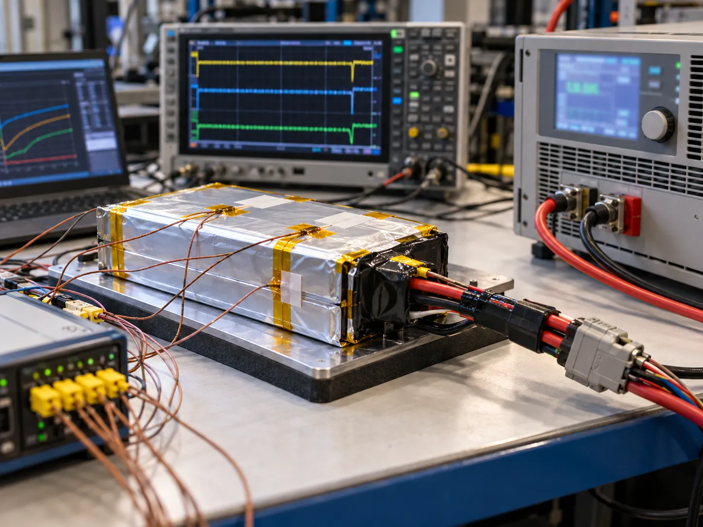
Failure diagnosis should follow the waveform. If the pack output collapses, inspect the cell and PCM. If pack voltage remains acceptable but PCB voltage falls, segment the harness, connector and board path. If the first pulse passes but later pulses fail, examine recovery time and heat accumulation. If prototypes pass but production varies, compare the released BOM, cell impedance distribution, FET revision, welds, crimp process, wire length and mating connector.
For connector identification, current-path details and production release controls, use the LiPo battery connector types guide. For protection selection, see the PCM and BMS selection guide.
For the broader prototype-to-release workflow, use Battery Pack Prototype Testing and Validation to define sample evidence, drawing review, acceptance criteria and production release controls.
7 Prepare an Engineering RFQ
A useful high discharge RFQ should allow the battery engineer to evaluate energy, power, protection and mechanical integration together. Include:
- Maximum finished battery dimensions, including cable exit and compression restrictions.
- Nominal capacity target and the real runtime or mission profile.
- Continuous current in amperes and the required duration or steady-state criterion.
- Pulse current in amperes, pulse width, repetition, rest time and event count.
- Minimum SOC and temperature at which the critical event must pass.
- Device brownout or reset threshold and the required voltage margin.
- Charge voltage, charge current and intended charging architecture.
- PCM behavior, connector mating part, polarity, wire gauge and wire length.
- Prototype quantity, annual forecast, target market and validation schedule.
Send the real waveform whenever possible. It is more useful than a label such as “high C rate” because it lets the engineer evaluate pulse duration, recovery, voltage margin and protection timing together. For project-specific cell and pack engineering, review THOR Power’s custom LiPo battery capability and submit the application conditions with the inquiry.
Engineering Decision
A high discharge LiPo battery should be selected from measured device requirements, not from a current label. Define the waveform, preserve PCB voltage margin, verify PCM timing and interconnect loss, and test the exact production-intent assembly across the conditions that matter. Once those boundaries and acceptance limits are documented, high discharge becomes a measurable engineering requirement that can be controlled through production.
Need a High-Discharge LiPo Battery for Your Device?
Send the real load waveform, continuous and pulse current, minimum PCB voltage, operating temperature, cavity size, connector and wire details, charging method, prototype quantity and production forecast. THOR Power can review the complete cell-to-device current path and define a production-intent validation plan.
FAQ: High-Discharge LiPo Battery Current
What makes a LiPo battery high discharge
There is no universal C-rate threshold for every pouch cell. In an OEM project, a high discharge LiPo battery is a specific cell and finished pack validated for the required continuous or pulse waveform within voltage, thermal, protection, life and safety limits.
Is peak current the same as pulse current
Not automatically. Peak is ambiguous unless its duration and repetition are defined. A release specification should state current in amperes, pulse width, repetition, rest time, SOC, temperature, minimum voltage and measurement boundary.
Can a 3C pulse rating be used continuously
Only if the supplier separately validates 3C as a continuous condition. A short pulse and a sustained load create different polarization, temperature and protection demands.
Why does a battery pass at room temperature but fail in the cold
Lower temperature can increase cell impedance and reduce loaded voltage. When the battery is also at low SOC, the same pulse may remove the device’s remaining brownout margin even though the room-temperature test passed.
What should be measured during a high current pulse test
Record current, pulse width, pre-pulse voltage, minimum pack voltage, minimum PCB-input voltage, temperature, protection behavior and recovery. Repeat the event at the relevant SOC, temperature and aging conditions.
Technical References
- [1] Anup Barai, Kotub Uddin, W. D. Widanage, Andrew McGordon and Paul Jennings. A study of the influence of measurement timescale on internal resistance characterisation methodologies for lithium-ion cells. Scientific Reports 8, 21 (2018). DOI 10.1038/s41598-017-18424-5. Pouch-cell resistance and measurement-timescale reference.
- [2] Idaho National Laboratory and U.S. Department of Energy. Battery Test Manual for Plug-In Hybrid Electric Vehicles (2008). HPPC and pulse-test methodology reference; not a small-pouch-cell product specification.
- [3] Brett Barr. How to Select a MOSFET Battery Protection. Texas Instruments, SSZT769, March 2018. Battery-protection MOSFET current-path and conduction-loss reference.
- [4] Simone Barcellona, Silvia Colnago, Giovanni Dotelli, Saverio Latorrata and Luigi Piegari. Aging effect on the variation of Li-ion battery resistance as function of temperature and state of charge. Journal of Energy Storage 50 (2022) 104658. DOI 10.1016/j.est.2022.104658. Temperature, SOC and aging dependence of internal resistance.
- [5] Jan Philipp Schmidt, Stefan Arnold, Andre Loges, Daniel Werner, Thomas Wetzel and Ellen Ivers-Tiffee. Measurement of the internal cell temperature via impedance: Evaluation and application of a new method. Journal of Power Sources 243 (2013) 110-117. DOI 10.1016/j.jpowsour.2013.06.013. Pouch-cell impedance dependence on temperature and SOC.
Evidence boundary: These references support general resistance, pulse-characterization and protection principles. They are not THOR Power product specifications. Final continuous current, pulse current, voltage, temperature and life limits must be confirmed for the exact cell and production-intent pack.