
LiPo Battery Dimensions: Why a Cell That Fits in CAD May Not Fit Your Product

Technical reviewer: Dr. Maximilian Weber
Chief Scientist at THOR Power. Reviews battery engineering content for technical accuracy, test boundaries and production relevance.

Author: Victor Xiong
OEM Division President at THOR Power, focused on custom lithium battery development and manufacturing for device programs.
Quick Answer
A LiPo pouch cell can fit in a CAD cavity and still fail after it becomes a finished battery. A model code usually identifies the approximate pouch body, while the device must accept the maximum finished assembly: the cell, protection circuit module (PCM), folded tabs, solder joints, insulation, label, lead wires and connector.
Approve the battery from the device inward. Define the minimum usable cavity, maximum finished battery thickness × width × length, local protrusion zones, wire-exit direction, connector envelope and keep-out zones. Then verify production-intent samples using an agreed measurement method. A nominal code such as 603040 is useful for screening; it is not a mechanical acceptance limit.
BUYER TAKEAWAY / The model number helps you shortlist a cell. The revision-controlled finished-battery drawing defines what must fit and what the supplier must deliver.
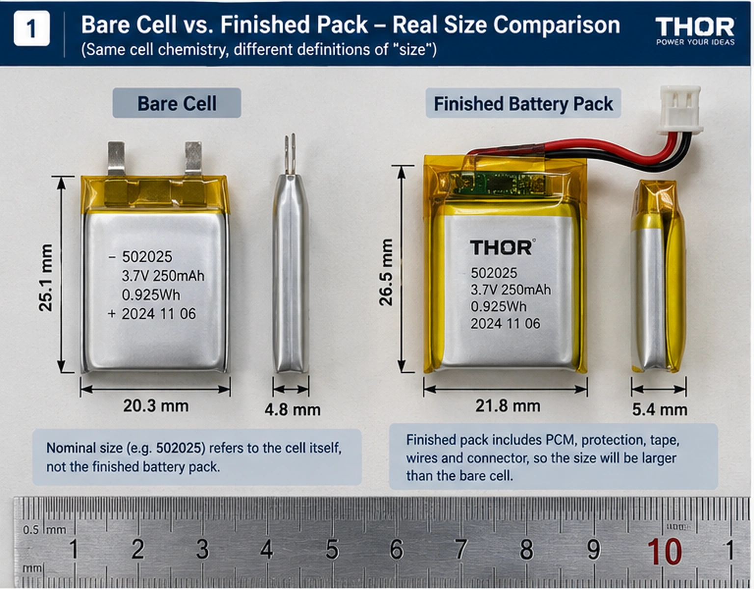
The THOR-502025 3.7V 250mAh LiPo battery is a practical example of this distinction: its 502025 model code describes a nominal 5.0 × 20 × 25 mm cell, while the finished battery with PCM is specified at 5.0 × 20 × 27 mm.
Four Questions to Answer Before Mechanical Approval
- Is the limit written as maximum finished-battery dimensions rather than only a nominal cell code?
- Have ribs, screw bosses, covers, PCB edges, adhesive, cable paths and connector mating access been included in the minimum usable cavity?
- Does the released drawing define tolerance, local protrusions, wire exit, connector orientation and the dimensional measurement method?
- Have multiple production-intent batteries been checked in representative enclosures without forcing the pouch to fit?
At a Glance: Five Different Meanings of “Battery Size”
| Dimension term | What it means | How to use it |
|---|---|---|
| Nominal cell size | Approximate pouch-body size used for model identification. | Initial screening only. |
| Maximum bare-cell envelope | Supplier-controlled cell-body limit, including the stated tolerance and defined measurement condition. | Cell-level design review. |
| Maximum finished-pack envelope | Cell plus PCM, tab folds, solder joints, insulation, tape and label. | Primary battery-cavity limit. |
| Wire and connector envelope | Wire exit, bend corridor, connector housing and mating/removal access. | Model separately from the main pack where needed. |
| Assembly and service margin | Remaining non-interference space after worst-case battery, enclosure and mounting stack-up. | Project-specific; agree on the required margin. |
Table of Contents
- 1. Nominal Cell Size vs Finished Battery Size
- 2. Where Pack Assembly Consumes Space
- 3. Thickness Risk and Measurement Conditions
- 4. Wire Exit and Connector Clearance
- 5. Why Forced Compression Is Not a Fit Strategy
- 6. Dimension Stack-Up: From Cavity to Pass/Fail Limit
- 7. Worked Compact-Device Fit Example
- 8. What to Change When the Prototype Does Not Fit
- 9. Drawing Release, Prototype Validation and Change Control
- 10. RFQ Information Buyers Should Send
- 11. FAQ
- 12. Technical References and Compliance Context
1. Nominal Cell Size vs Finished Battery Size
Pouch-cell model numbers are useful for searching by approximate geometry. A code such as 603040 commonly points to a cell body around 6.0 mm thick, 30 mm wide and 40 mm long. Naming order, rounding and tolerances vary by manufacturer, so treat the code as a search shorthand, not a guaranteed mechanical envelope.
The common mistake is using those nominal numbers as the outside dimensions of the protected battery installed in the device. A finished pack can add a PCM, folded tabs, solder joints, insulation, tape, label, lead wires and connector. These additions do not consume space uniformly: one may extend length while another creates a local thickness peak.
Use a custom LiPo battery page or size catalogue to shortlist candidate footprints. Final mechanical approval should use a revision-controlled finished-battery drawing with maximum dimensions and defined measurement conditions. View THOR Power custom LiPo battery options
2. Where Pack Assembly Consumes Space
A finished LiPo battery does not grow equally in every direction. The result depends on the PCM position, tab-fold geometry, solder-joint height, insulation construction and cable routing. Adding one generic allowance to thickness, width and length is therefore unreliable.
| Pack feature | Where space is consumed | Failure mode if omitted |
|---|---|---|
| PCM / protection PCB | Usually near the tab end; may add local thickness, width or length. | The pouch fits, but the protected end interferes with a rib or cover. |
| Tab fold / solder joint | Concentrated at one end and often not represented by the center-body thickness. | A local high point causes cover pressure or assembly variation. |
| Tape / insulation / label | Faces, edges and PCM area. | Several thin layers consume a tight tolerance budget. |
| Lead-wire exit | Outside the pouch body and dependent on exit direction. | The wire is pinched or forced across a sharp edge. |
| Connector | Separate three-dimensional volume plus mating access. | The connector fits in CAD but cannot be plugged in during assembly. |
Ask the supplier to show three boundaries on the drawing: maximum bare-cell envelope, maximum finished main-pack envelope, and external wire/connector envelope. This becomes especially important during a capacity upgrade, when a similar pouch footprint may still require a different thickness, PCM layout or tab arrangement.
3. Thickness Risk and Measurement Conditions
A pouch cell is not a rigid machined block. Reported thickness can be influenced by manufacturing spread, state of charge (SOC), temperature, aging state, rest time and measurement method. The PCM or folded-tab region may also be thicker than the center of the pouch. A single center-point measurement can therefore miss the actual interference location.
For a tight product, the customer and supplier should agree on how finished dimensions are measured. The objective is a repeatable acceptance result, not extra gauge pressure that makes the sample appear thinner.
Measurement conditions to place on the drawing or inspection plan
| Condition | What must be defined | Why it changes the result |
|---|---|---|
| Battery state | SOC range, charge/discharge history and whether the pack is new or aged. | Electrochemical and mechanical state can influence pouch thickness. |
| Environment | Controlled temperature and any required conditioning time. | A measurement without environmental context may not be repeatable. |
| Rest time | Time between charge/discharge and dimensional inspection. | Immediate and stabilized measurements may differ. |
| Instrument | Caliper, thickness gauge, optical method or agreed fixture. | Different tools contact the flexible pouch differently. |
| Contact method | Contact area, location and applied force or fixture condition. | Small anvils or excessive force can under-report or distort local thickness. |
| Measurement locations | Center body plus PCM, tab, edge and other local high points. | The maximum local envelope controls fit. |
| Sampling | Number of packs, lots and production stages to inspect. | One prototype does not represent production spread. |
DO NOT TURN ABNORMAL SWELLING INTO A CLEARANCE RULE / Normal released dimensional variation may be included in the tolerance and assembly margin. Abnormal gas generation or swelling is a failure condition that requires root-cause investigation; spare cavity space does not make it acceptable. Reference 3 provides background evidence for pouch-cell swelling under selected conditions, not a universal device-clearance value.
4. Wire Exit and Connector Clearance
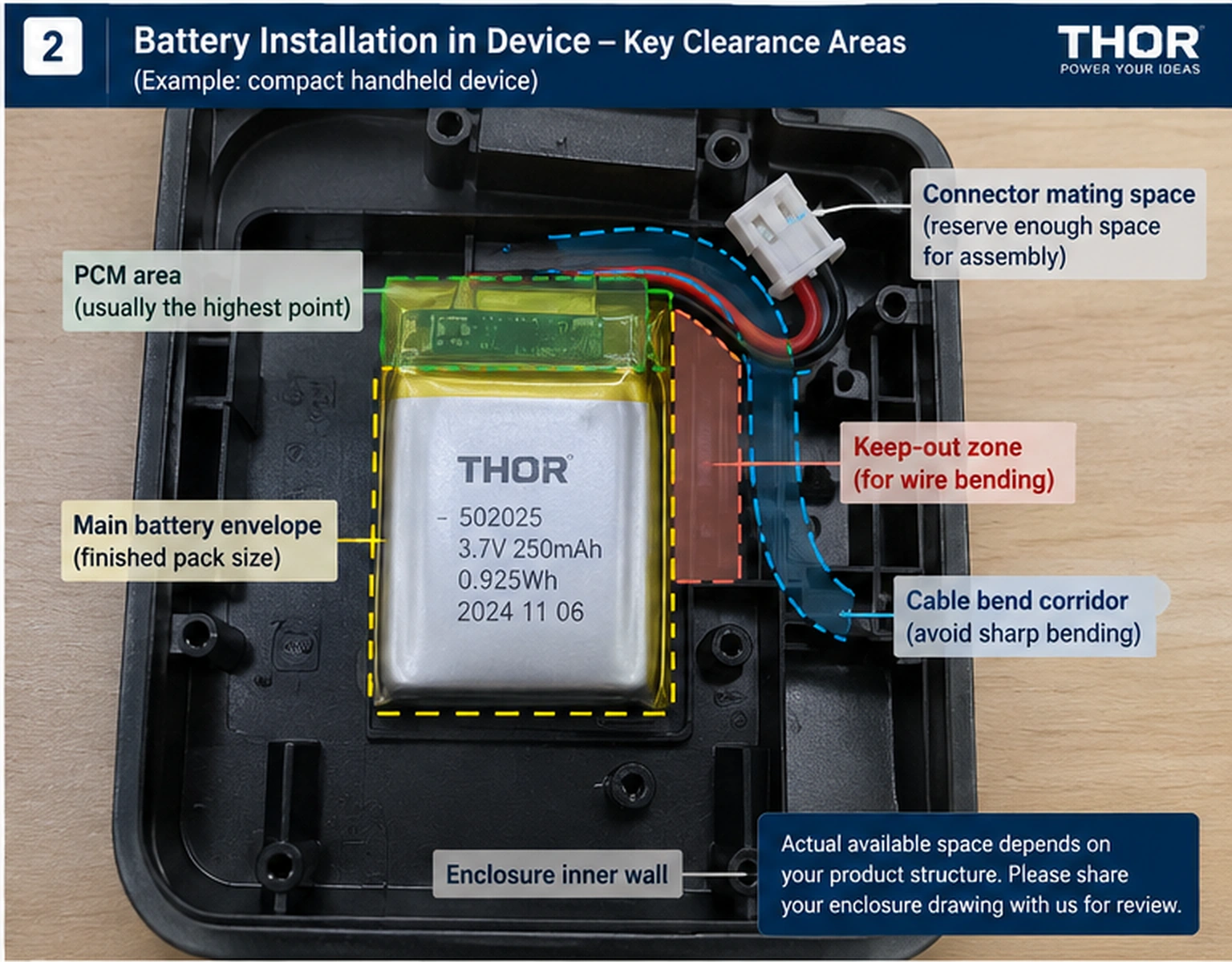
Many samples fail after the battery body has passed the size check. The interference appears only when the cable turns toward the PCB, crosses a housing rib or reaches a connector that still needs room to mate.
Specify the exit side, viewing direction, wire gauge, conductor count, wire-length reference points, connector manufacturer and series, orientation, polarity and mating part. “Left exit” and “right exit” are ambiguous unless the drawing states the viewing direction. An annotated installation photo can remove that ambiguity.
Treat the connector as an installation operation, not just a static solid. Reserve space for the housing, cable transition, mating stroke and service removal where required. Route the cable so it does not transfer sustained force into the pouch edge, tabs or solder joints.
5. Why Forced Compression Is Not a Fit Strategy
If a sample is slightly too thick, the enclosure should not simply press it into compliance. Mechanical force should not be used to convert an out-of-envelope battery into an acceptable one.
Hard ribs, screw bosses, sharp edges or uneven cover pressure can create concentrated loads near the pouch edge, tabs, solder joints or wire exit. A prototype that closes once may still fail across production variation, vibration or repeated servicing.
Some products intentionally use controlled constraint. In that case, engineer the interface with the battery supplier: define permitted contact surfaces, support uniformity, material stack, applicable force limits, assembly method and validation plan. Do not improvise constraint after cell selection.
6. Dimension Stack-Up: From Cavity to Pass/Fail Limit
Mechanical approval should be calculated independently for thickness, width and length. For each axis i:
WORST-CASE AVAILABLE MARGIN / Mᵢ = Cmin,ᵢ − Bmax,ᵢ − Amax,ᵢ for i ∈ {thickness, width, length}
| Term | Definition |
|---|---|
| Cmin,ᵢ | Minimum usable device cavity on axis i after enclosure, PCB, rib, boss and neighboring-part tolerances. |
| Bmax,ᵢ | Maximum finished-battery envelope on axis i under the released measurement condition. |
| Amax,ᵢ | Maximum additional assembly consumption on axis i, such as adhesive, foam, carrier, insulation or intentional positional allowance. |
| Mᵢ | Remaining non-interference margin. A negative result is a clear failure. A non-negative result still must meet the project’s required assembly and service margin. |
Do not combine the three axes into a single number. A pack can have ample length while failing at a local thickness peak. Likewise, the main battery envelope can pass while the cable or connector envelope still interferes.
If statistical tolerancing is used instead of worst-case stack-up, document the assumptions, process capability and accepted risk. Do not replace controlled minimum and maximum limits with nominal CAD dimensions without an approved rationale.
7. Worked Compact-Device Fit Example
The following calculation is hypothetical and demonstrates the method only. It is not a THOR Power product specification and does not imply that all cells sharing a model code have identical dimensions.
Assume the released minimum usable cavity is 5.40 × 20.60 × 27.00 mm. A nominal 502025 cell appears to leave 0.40 mm in thickness, 0.60 mm in width and 2.00 mm in length. That nominal comparison is incomplete because it omits the finished-pack maximum and the device assembly stack.
| Axis | Cavity minimum Cmin | Finished battery maximum Bmax | Other stack Amax | Available margin M | Decision |
|---|---|---|---|---|---|
| Thickness | 5.40 mm | 5.30 mm at local PCM zone | 0.15 mm adhesive | −0.05 mm | FAIL: hard interference |
| Width | 20.60 mm | 20.30 mm | 0.10 mm positioning stack | +0.20 mm | Provisional pass |
| Length | 27.00 mm | 26.40 mm | 0.20 mm end stack | +0.40 mm | Provisional pass |
Thickness fails even though the nominal model code appeared to fit. Width and length are only provisional passes because the required project margin and the wire/connector envelope still need approval.
Possible corrections include a thinner pouch, a different PCM position, a reduced approved adhesive stack, an enclosure change, connector relocation, another wire exit or a revised capacity target. Correct the controlling interference rather than subtracting one arbitrary allowance from every axis.
If runtime is driving the request for a thicker cell, evaluate the mechanical tradeoff together with the LiPo battery capacity and runtime guide.
8. What to Change When the Prototype Does Not Fit
Use this sequence before requesting a new battery model. It separates a definition problem from a true dimensional failure.
- Confirm whether the dimensions being compared are nominal cell size, maximum bare-cell size or maximum finished-pack size.
- Measure the actual interference location, including the PCM, tab fold, solder joint and pouch edges—not only the center of the pouch.
- Check the battery and enclosure against their released maximum and minimum drawings using the agreed measurement method.
- Inspect adhesive, foam, labels, carriers, cable paths, ribs and cover features added after the first CAD fit check.
- Verify wire-exit direction, connector orientation, mating stroke and cable-bend corridor in the real assembly sequence.
- Determine whether the issue is isolated to one sample or appears across multiple production-intent units and enclosure samples.
- Correct the controlling item: pouch size, PCM location, assembly stack, cable layout, connector position, enclosure geometry or capacity target.
USEFUL EVIDENCE FOR A SUPPLIER REVIEW / Send the approved cavity drawing, photos of the interference, measured locations, battery lot or sample identification, enclosure revision and the exact assembly sequence. “The battery is too large” is not enough to identify the cause.
9. Drawing Release, Prototype Validation and Change Control
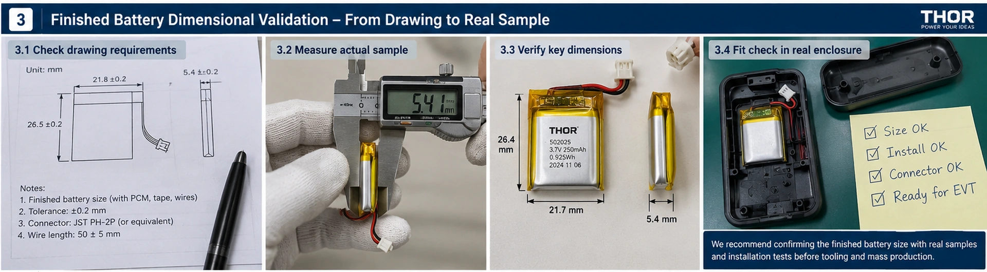
One hand-built sample fitting once does not prove production compatibility. Mechanical release should connect the approved drawings, representative samples and the real device.
| Stage | What to verify | Required evidence |
|---|---|---|
| Drawing review | Maximum finished envelope, local protrusion zones, measurement conditions, wire exit and connector. | Approved battery and cavity drawing revisions. |
| Sample inspection | Multiple packs measured at defined locations using the agreed method. | Dimensional record, sample IDs and photos. |
| Device fit | Insertion, retention, cover closure, cable route and connector mating. | Pass/fail fit record in representative enclosures. |
| Use-condition validation | Battery position and interfaces remain acceptable under the product’s intended conditions. | Device validation record and agreed acceptance criteria. |
| Production control | Finished dimensions, traceability and relevant process controls. | Inspection plan, fixture or gauge definition and lot records. |
| Change control | Any change to cell source, PCM, tape, label, wire, connector or enclosure that can affect fit. | Documented impact review and revalidation decision. |
A go/no-go fixture can help control a critical dimension, but it must represent the released envelope and inspection method. It should verify compliance, not compress the pouch through an opening smaller than the approved limit.
THOR POWER ENGINEERING NOTE / For tight-fit OEM inquiries, we do not treat the pouch model code as the final size. Before sample build, our engineering review asks for the maximum finished-battery envelope or cavity drawing, then confirms PCM position, wire exit, connector model and polarity, and installation direction. When “left” or “right” wire exit is ambiguous, an annotated device photo is usually more reliable than text alone. The sample is checked against the finished-pack drawing, not only the bare cell.
10. RFQ Information Buyers Should Send
A strong RFQ starts with product constraints and electrical load, then treats the model code as a candidate. The following inputs let the supplier evaluate mechanical fit and electrical performance together.
| Buyer input | What to provide | Why it matters |
|---|---|---|
| Mechanical limit | Maximum finished battery T × W × L, or minimum usable cavity with tolerance. | Defines the real pass/fail boundary. |
| Cavity evidence | Annotated drawing, section view or CAD screenshot with ribs, bosses and allowed extension zones. | Shows local constraints that three numbers cannot describe. |
| Electrical load | Capacity target, continuous current, peak current, pulse duration and cutoff voltage. | Balances runtime and load capability against package size. |
| Cable and connector | Exact connector or mating part, polarity, orientation, wire gauge, length reference and exit direction. | Prevents drop-in and routing errors. |
| Protection and sensing | PCM functions, NTC value/location and any communication requirement. | Affects component selection and local pack stack-up. |
| Project route | Prototype quantity, annual forecast, target markets and certification expectations. | Defines validation, traceability and production planning. |
Once the finished envelope is defined, use the LiPo battery models page to shortlist candidate pouch footprints.
For an engineering review, request a battery solution and attach the cavity drawing, load profile, finished-size limit, connector, wire and protection requirements.
Key Takeaways
- Screen with the nominal model code; approve with a maximum finished-battery drawing.
- Calculate thickness, width and length separately using the minimum cavity and maximum finished assembly.
- Define SOC, temperature, rest time, instrument, contact method, measurement locations and sampling before dimensions become acceptance criteria.
- Model the wire route, connector body and mating access as their own envelope.
- Validate multiple production-intent packs and control changes that can alter the finished envelope.
Conclusion
For compact OEM products, “battery size” should be separated into the nominal model code, maximum bare-cell envelope, maximum finished-pack envelope and the routing volume required by wires and connector. A fit decision based only on the model code leaves critical variables undefined.
Define the minimum usable cavity, calculate worst-case margin by axis, agree on the measurement method and validate production-intent samples in the real device. This moves fit problems from sample rework into drawing review, where changes are faster and less expensive.
Planning a compact OEM product? Request a Battery Solution with your cavity drawing, finished-size limit, load profile, connector, wire length and protection requirements.
11. FAQ
Does a 603040 LiPo battery always measure exactly 6 × 30 × 40 mm?
No. The model code is normally an approximate size identifier. Naming conventions, rounding and tolerances vary, so use the released supplier drawing for acceptance.
Should I send the cavity size or the cell model I want?
Send the minimum usable cavity or maximum finished-battery dimensions first. You may include a preferred model as a candidate, but it should not replace the mechanical limit.
Does the PCM count in battery dimensions?
Yes. For a protected battery, the PCM, folded tabs, solder joints, insulation, tape and label must be included in the finished mechanical definition.
How should wire length be specified?
Define both measurement reference points, then state wire gauge, conductor count, exit direction, connector model, orientation and polarity.
Can I press a LiPo battery slightly to make it fit?
Do not use forced compression as a general correction. If the device intentionally constrains the battery, design and validate the interface with the supplier.
How much clearance should I leave around a LiPo battery?
There is no universal value. The required margin depends on the released battery envelope, enclosure tolerance, mounting stack, assembly process and expected use conditions.
Why can production batteries feel tighter than the first sample?
Possible causes include normal dimensional spread, enclosure variation, adhesive or tape stack-up, measurement differences or a configuration change. Compare both parts with their released drawings and sample records.
Is swelling allowance the same as normal assembly clearance?
No. Assembly margin prevents expected dimensional variation from becoming hard interference. Abnormal swelling is a failure condition that requires investigation rather than automatic acceptance.
12. Technical References and Compliance Context
- IEC 62133-2:2017 + AMD1:2021 — Safety requirements for portable sealed secondary lithium cells and batteries, including relevant safety and mechanical test context. IEC official publication
- UNECE, UN Manual of Tests and Criteria, Revision 8 (2023) and Amendment 1 (2025) — lithium-battery transport testing context, including changes relevant to Section 38.3. UNECE Revision 8 files
- NASA Technical Reports Server — public pouch-cell swelling investigation under selected storage, electrical-abuse and environmental conditions. This evidence does not establish a universal device-clearance value. NASA record 20120016551
- UL Solutions — general battery safety testing and certification context. UL battery safety testing
PROJECT CONTROL NOTE / For any specific project, the exact production cell datasheet, revision-controlled dimensional drawing, finished-battery assembly drawing and mutually approved inspection method remain the controlling mechanical documents.
Compliance Context
IEC 62133-2, UN 38.3 and other safety or transport requirements do not create a universal LiPo dimensional-clearance rule. References 1, 2 and 4 provide safety, transport and certification context; they do not define the cavity margin for a specific product. The exact cell specification, finished-pack drawing, device design, measurement method, validation plan and target-market compliance route remain project-specific.
Related Engineering Guides



Dr. Maximilian Weber is THOR Power's Chief Scientist and a senior expert in lithium battery technology. His technical review focuses on battery safety, performance optimization, energy density and custom battery solution development.
Last technical review: September 2026

Victor Xiong holds a Master's degree from The Chinese University of Hong Kong, Shenzhen. He leads THOR Power's OEM Division and focuses on custom battery solutions for global device brands, product developers and industrial customers.