What Size LiPo Battery Fits My Device?

Technically Reviewed By
Chief Scientist
Dr. Maximilian Weber is THOR Power’s Chief Scientist and a senior expert in lithium battery technology. His technical review focuses on battery safety, performance optimization, energy density and custom battery solution development.
Last technical review: September 2026

Written By
President of OEM Division & Custom Battery Specialist
Victor Xiong holds a Master’s degree from The Chinese University of Hong Kong, Shenzhen. He leads THOR Power’s OEM Division and focuses on custom battery solutions for global device brands, product developers and industrial customers.
Last technical review: August 2026
The Real Problem: The Cell Fits on Paper, but the Finished Battery Does Not
A product has a battery cavity measuring 6.0 mm thickness × 35 mm width × 45 mm length (T × W × L). The buyer finds a LiPo cell below those nominal dimensions, confirms voltage and capacity, and orders samples. The protected sample arrives – and the rear cover will not close, the wire cannot route, or one end of the pack presses against the enclosure. Always label the dimension order explicitly; do not assume the buyer and supplier use the same T × W × L or L × W × T convention.
The mistake usually happens before the sample is ordered: the cavity is approved against bare pouch size instead of the maximum finished assembly size in the actual device.
A battery should not be approved by bare pouch size alone; it should be approved by the maximum finished assembly size in the actual device. The largest pouch cell that fits a cavity is usually not the largest battery that should be specified. Mechanical approval must use the maximum finished-pack envelope – including PCM, tabs, insulation, label, wires, connector, NTC, mounting material, tolerance and the installation space needed by the final product.
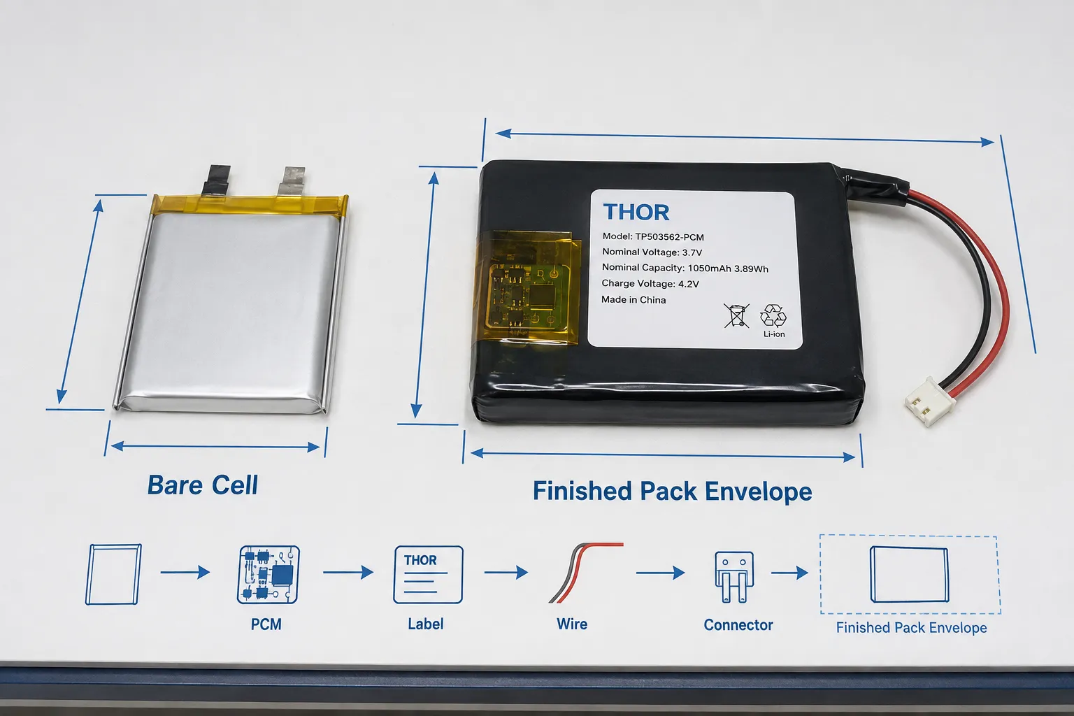
If your sample is “the right size” but the enclosure still will not close, do not immediately sacrifice capacity by choosing a thinner cell. First locate the exact interference: cell body, local PCM stack, wire bend radius, connector mating space, adhesive/foam or a housing keep-out.
Define the Usable Battery Envelope Before Choosing a Cell
A cavity drawing may show length, width and thickness, but not every millimeter inside that rectangular box belongs to the battery. Screw bosses, enclosure ribs, PCB edges, curved walls, connector mating space, cable routing, antennas, sensors, adhesive and insertion direction can all reduce the usable volume.
The first approval question is therefore not “What cell fits inside L × W × T?” It is “What complete production battery assembly can be installed, routed, connected and closed without interference under the worst approved dimensions?”
Do not compare a nominal battery with a nominal CAD cavity. For production fit, compare the maximum approved finished-pack envelope with the minimum approved usable cavity after enclosure tolerances. A three-axis bounding-box check is necessary, but local ribs, curved walls, connector paths and cable bends can still create interference; tight products need a local 3D stack-up or CAD interference check.
Bare Cell Size Is Not Finished-Pack Size
The pouch body is only one part of an OEM battery. A production assembly may add tabs, PCM/protection circuit, insulation, label, lead wires, connector, NTC and mechanical support. Where those parts are placed determines whether length, thickness, routing space or local keep-out clearance becomes the limiting dimension. For a controlled finished envelope, the cell, protection and harness should be reviewed as one custom LiPo battery assembly. Panasonic Energy similarly states that lithium-ion cells should be integrated into properly designed systems with appropriate safety measures.
| Pack element | Where it consumes space | Typical design mistake |
|---|---|---|
| PCM at cell end | Overall length | Cell length is approved before the protection board is added. |
| PCM folded onto pouch | Local thickness | Nominal center thickness is checked, but the protected end is thicker. |
| Wire exit and strain relief | Routing envelope | Battery body fits, but the wire must bend through a rib or sharp corner. |
| Connector and mating area | Length / adjacent cavity | Connector body is excluded from the space review. |
| Label, insulation, adhesive or foam | Thickness / local stack | Small layers consume the remaining mechanical margin. |
IEC 61960-3:2017 includes dimensional requirements and specifically adds Annex A for “Dimensions of the cell with a laminate film case.” That supports treating pouch-cell dimensions as controlled cell-level characteristics, but it does not replace the controlled drawing for the finished OEM battery assembly [2].
Where PCM, Wires and Connectors Consume Space
Thickness is the dimension most likely to look acceptable in a spreadsheet and fail in the enclosure. A nominal pouch thickness is not the same as the maximum local thickness of the finished protected pack. The protection architecture and placement should be frozen with the PCM/BMS Selection Guide before mechanical release.
M_fit = D_cavity,min – D_pack,max – C_install. Here D_cavity,min is the minimum approved usable space at the location being checked, D_pack,max is the maximum finished-pack dimension at that location, and C_install is the project-specific installation clearance. M_fit > 0 is only a geometric screening pass; M_fit ≤ 0 means the design has no release margin at that location. Local 3D interference and assembly-path checks are still required.
Illustrative screening example
Suppose the minimum approved usable thickness at one local section is 6.0 mm. A nominal 5.5 mm pouch appears to leave 0.5 mm. If the selected protection arrangement creates a 0.6 mm local stack above the pouch body, the local assembly is already 6.1 mm before label, adhesive, pack tolerance or installation clearance are considered. At that location, M_fit = 6.0 – 6.1 – C_install < 0. The “5.5 mm cell” passed a nominal check; the finished pack failed the worst-case fit check.
If the enclosure pressure occurs only near the protected end, reducing the entire cell thickness may sacrifice capacity unnecessarily. Measure the pack by location and find the actual local maximum first.
A Battery Can Fit but Still Be Impossible to Assemble
Mechanical fit includes the path used to install and connect the battery. A pouch can sit inside the cavity yet fail production assembly because the harness cannot bend, the connector cannot mate, or the pack must be forced past a housing feature.
For thin wearables, GPS units, handheld electronics and compact medical or monitoring devices, wire-exit direction can be as important as cell size. Changing the wire exit or PCM orientation can sometimes preserve more capacity than reducing the pouch dimensions. Use the Connector, Wire Gauge and NTC Selection Guide to define the complete routing envelope.
Confirm wire exit side, wire gauge, minimum practical bend area, connector body, mating direction, strain relief, nearby edges and the insertion sequence. The correct battery drawing must describe these features, not only the pouch body.
If the enclosure must compress the pouch, PCM or harness to close, treat that as an interference condition – not proof of fit – unless controlled compression is explicitly defined and qualified for the exact cell/pack design. Do not use cover force to recover missing tolerance margin.
Engineering Case: The “Too-Thick Cell” Was Not Too Thick
Project situation: A compact handheld product passed the early cavity review with the selected pouch cell, but the first protected sample created pressure against the rear enclosure.
Hidden risk: The team had compared cavity thickness with the pouch body. The local PCM-and-insulation stack at one end of the finished pack was the actual interference point.
Engineering response: The finished assembly was measured by location and compared with the local enclosure profile. The interference was localized at the protected end rather than across the pouch body. The cell body itself remained inside the intended envelope, so the protection-board placement and stack-up were revised before changing cell capacity.
Buyer lesson: When a LiPo battery does not fit, identify where the maximum finished envelope exceeds the cavity before selecting a lower-capacity cell.
How to Maximize Capacity Without Creating a Fit Problem
Start with the product boundary, then optimize the battery. The highest practical capacity is the highest suitable cell-and-pack configuration whose maximum production envelope remains inside the approved mechanical boundary. The goal is not the largest bare pouch cell; it is the largest finished assembly that can be repeatedly built, installed and closed without enclosure pressure. Confirm that the mechanically viable option still meets the real duty cycle with the Battery Runtime Calculation Guide.
| Decision input | What to define | Why it changes the battery choice |
|---|---|---|
| Hard dimensions | Minimum approved usable L × W × T after enclosure tolerances, plus the dimension that cannot move | Supports worst-case comparison against the maximum finished pack, not nominal CAD space. |
| Keep-outs | Ribs, screws, PCB, curved walls, connector and cable path | Prevents a rectangular cell search from ignoring local interference. |
| Finished battery features | PCM, NTC, wire length/exit, connector, label, foam/adhesive | Lets the supplier optimize the complete pack rather than the bare pouch. |
| Electrical requirement | Voltage, runtime/capacity, continuous and peak current | Prevents a mechanically attractive cell from failing the real load. |
Do not design the enclosure from a model code alone. A code such as 503040 may be used by a supplier as a nominal size designation, but naming conventions are not a mechanical approval standard. Confirm the supplier’s dimension order, dimensional tolerance and controlled drawing for the exact finished configuration.
What to Send for a Useful First Review
Cavity drawing or CAD screenshot with minimum approved usable L × W × T under enclosure tolerances; label the dimension order explicitly.
Ribs, screws, PCB edges, curved walls and other keep-out areas.
The dimension that is truly fixed and the dimensions that can move.
Required voltage, target runtime/capacity, continuous current and peak current.
PCM requirement, connector, polarity, wire gauge/length and exit direction.
NTC or auxiliary-wire requirement, mounting method and operating temperature.
Product photo or assembly sequence if the harness route is constrained.
Tell the supplier which dimension cannot change. “Thickness must stay below 6.0 mm, but length can increase by 3 mm” is far more useful than “please give me the highest-capacity battery.”
Final Fit Approval Rule
One nominal or hand-selected sample fitting the enclosure is not production release evidence. Approve the maximum production-intent battery envelope against the minimum approved usable cavity, together with PCM location, wire exit, connector routing, mounting stack, dimensional tolerances and final enclosure closure. Close the fit review through controlled drawing → tolerance stack → production-intent samples → repeatable final assembly. If any boundary is unknown, mechanical fit is not closed.
Record the release evidence with the Battery Pack Prototype Testing Guide.
Mechanical fit approval does not replace portable-lithium safety qualification under IEC 62133-2:2017+A1:2021 where that standard applies.
Key Takeaways
Compare the maximum approved finished-pack envelope with the minimum approved usable cavity – not nominal battery size with nominal CAD space.
The controlling geometry includes local stack-up, not only overall L × W × T.
A bounding-box pass can still fail when ribs, curved walls or harness routing create local interference.
Thickness and the protected end of the pouch are common places where nominal margin disappears.
Do not reduce cell capacity until the exact interference point has been measured; a local PCM or routing change may recover the margin.
One fitted sample is not production release evidence; close the fit with tolerance stack-up and production-intent assembly checks.
Conclusion
The best LiPo fit decision is not “find the biggest cell below three cavity dimensions.” It is to define the real usable envelope, compare the minimum approved cavity with the maximum finished pack, and verify local stack-up, connector position and routing in the final enclosure.
That turns a vague size request into a controlled mechanical requirement – and avoids sacrificing capacity to solve a problem that may actually be caused by PCM placement, harness routing, enclosure geometry or tolerance overlap.
Planning a LiPo Battery for a Tight Product Space?
Share the cavity drawing, maximum dimensions, required runtime, load profile, connector and PCM/NTC requirements. THOR Power can review the usable envelope before the cell architecture is frozen. Start with a custom battery engineering review.
FAQ: LiPo Battery Size and Device Fit
Can I choose a LiPo battery with the same dimensions as my battery cavity?
Not from nominal dimensions alone. The maximum finished battery must account for protection components, insulation, harness routing, dimensional tolerance, mounting materials and the actual enclosure geometry.
Does adding a PCM increase LiPo battery size?
It changes the finished envelope. A PCM beyond the pouch can increase length, while a folded PCM can create a local thickness maximum even when overall length stays similar.
Is a LiPo model number such as 503040 the exact finished battery size?
No. Treat the model code as a nominal size reference. Mechanical approval should use the controlled drawing for the exact cell and finished pack configuration.
Why does my LiPo battery fit without the back cover but not after assembly?
Common causes are a local PCM stack, cable routing, connector position, adhesive or foam, enclosure ribs, curved housing surfaces or insufficient tolerance margin. Measure the installed assembly by location.
How do I get the highest LiPo capacity into a fixed space?
Define the real usable 3D envelope and hard keep-outs first, then optimize cell dimensions, PCM position and harness routing together. Capacity should be maximized only after the finished pack boundary is known.
Is one fitted LiPo sample enough to approve production?
No. A nominal or hand-selected sample can fit while the maximum finished-pack tolerance and minimum enclosure tolerance overlap in production. Approve the controlled drawing and tolerance stack, then confirm repeatable closure with production-intent samples.
How much clearance should I leave around a LiPo battery?
There is no universal value. Clearance depends on the exact cell and pack tolerances, dimensional-change criteria, mounting method, enclosure geometry and installation process. Use the controlled project drawing and validation evidence.
The dimensional examples in this article are engineering screening examples, not universal design allowances. Final approval must use the exact cell/pack drawing, project-specific tolerances, enclosure geometry, assembly method and production-intent validation. Engineering cases reflect recurring issues encountered during battery-project reviews; identifying details and selected values may be adjusted to protect customer confidentiality.