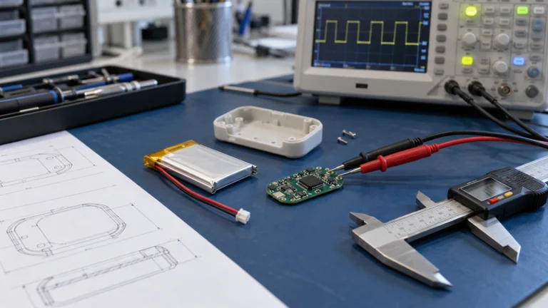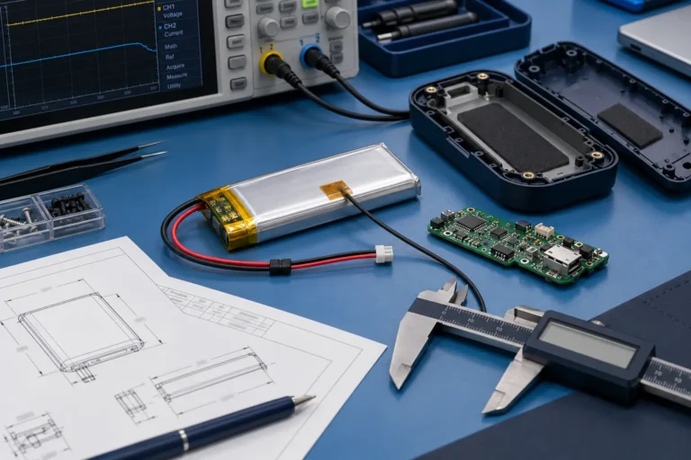
Battery Pack Prototype Testing: From First Sample to Final-Device Validation

Technically Reviewed By
Chief Scientist
Dr. Maximilian Weber is THOR Power’s Chief Scientist and a senior expert in lithium battery technology. His technical review focuses on battery safety, performance optimization, energy density and custom battery solution development.
Last technical review: September 2026

Written By
President of OEM Division & Custom Battery Specialist
Victor Xiong holds a Master’s degree from The Chinese University of Hong Kong, Shenzhen. He leads THOR Power’s OEM Division and focuses on custom battery solutions for global device brands, product developers and industrial customers.
Last technical review: July 2026
ARTICLE NAVIGATION AND SERIES POSITION
This final article in THOR Power’s Battery Engineering Series brings together pack architecture, runtime, PCM/BMS selection, connector and wire design, thermal management and production control into one prototype-approval workflow. Use the Custom Battery Pack Design Guide as the parent article; the relevant specialist guides are linked later at the engineering decisions they support.
The first custom battery sample powered the product on the bench. Capacity looked acceptable, the connector fit and the protection board did not trip. Two weeks later, the integrated prototype reset during motor startup, stopped charging in a cold room and developed an intermittent fault after the housing was closed. The supplier said the battery had passed testing. The customer said the product did not work. Both statements were true because the two teams had tested different questions.
This is where many battery projects lose time. A first sample is treated as product approval, a short resistor-load test is treated as a real duty cycle, and a hand-built pack is treated as proof that mass production will be repeatable. The failure appears late, after tooling, firmware and certification planning have already moved forward.
Quick answer
A custom battery sample should not be approved only because it reaches nominal voltage and capacity on a bench. Approval requires a traceable, production-intent battery tested in the final device across the real load profile, charging states, temperature range, mechanical installation, protection behavior, faults and recovery. Certification and UN 38.3 do not replace this system-level validation.
Three approval questions
Did the test represent the real requirement? Was the sample equivalent to the intended production design? Can the normal production process repeat the approved result? A project is not ready for mass production until all three answers are supported by evidence.
CASE TRANSPARENCY NOTE
The engineering cases in this article are representative composite scenarios based on recurring battery-project patterns. They explain diagnostic and approval decisions without identifying a specific customer or presenting confidential project data as a named THOR Power case study.
Prototype Approval Is Not Product Approval
A battery prototype can prove several useful things: the proposed voltage is available, the cell arrangement can be assembled, the connector can be fitted and a protection circuit can operate. It cannot, by itself, prove that the complete product will meet runtime, charging, thermal, mechanical, life, safety and production requirements.
The distinction is easier to remember in three lines:
- A sample proves that one assembly can be built and tested.
- Design validation proves that the defined design meets the intended requirements in the product.
- Production validation proves that the manufacturing process can repeat that design without special handling or hand-selected parts.
NASA battery guidance separates engineering evaluation, qualification, lot acceptance and unit-level acceptance because each stage answers a different risk question [1,2]. Commercial OEM projects do not need to copy an aerospace test program, but the underlying lesson is directly applicable: evidence from one stage should not be used to approve a different stage.
In practice, a compact pouch-cell product, a high-current cylindrical-cell product and a backup-power module usually need different validation evidence. Early sample planning should therefore match the intended battery architecture, whether the project uses custom LiPo batteries, 18650 / 21700 battery packs or lithium-ion / LiFePO4 battery packs.
Core engineering principle
A battery pack should be approved against a written requirement and a controlled configuration, not against the memory of a good sample. The final evidence must identify what was built, how it was tested, what passed, what failed and which changes require revalidation.
Why the First Battery Sample Often Creates False Confidence
The first sample is usually built under favorable conditions. It may use freshly selected cells, short wires, a laboratory charger, an open enclosure and a simple electronic load. The final product adds the conditions that expose the real weaknesses: startup pulses, constant-power behavior at low state of charge, charge-while-use, heat from adjacent electronics, cable routing, foam compression, firmware timing, cold charging limits and repeated duty cycles.
A bench test can be technically correct and still be irrelevant to the product. Common examples include:
- Testing average current while the device fails on a millisecond or second-level startup pulse.
- Measuring pack-terminal voltage while the product sees a lower voltage after the connector, wire and switch path.
- Charging the battery with a laboratory supply while the final charger uses different termination, restart or temperature logic.
- Testing the loose pack in free air while the final enclosure restricts cooling or compresses the pouch cell.
- Approving a hand-built unit without defining the cell lot, BMS firmware, welding process, harness or thermal materials that production must repeat.
COMPOSITE ENGINEERING CASE 1 — CAPACITY PASSED, THE DEVICE STILL REBOOTED
Project situation: A portable motorized device met the requested amp-hour capacity during a low-rate discharge.
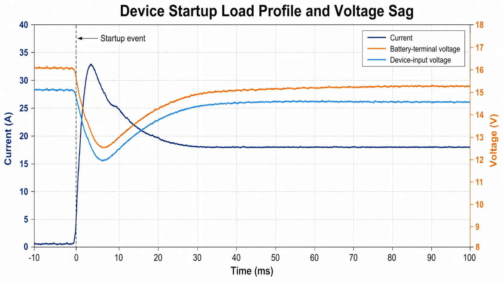
Hidden risk: In the product, a short startup pulse caused voltage at the controller input to fall below its reset threshold. The cells were not empty; the combined cell resistance, connector contact, harness and BMS path created the failure.
Engineering response: The team captured current and voltage at the cells, pack output and controller input during startup, then corrected the limiting current path.
Buyer lesson: A capacity result cannot approve startup performance. Diagnose the complete loaded-voltage path before increasing the capacity label.
Define What Each Prototype Stage Must Prove
Many hardware teams use the labels EVT, DVT and PVT. Those names are useful shorthand, but they are not universal battery standards. One company may call a hand-built fit sample DVT while another reserves DVT for a production-intent build. The approval record should therefore state the evidence required at each stage rather than relying on the label alone. The same stage definitions should be frozen for the selected battery product family.
| Sample stage | Question it should answer | Expected construction | What it should not approve |
|---|---|---|---|
| Mechanical fit sample | Does the pack fit the available space and interface? | Mock cell, dummy mass, early harness or non-final housing may be acceptable. | Runtime, safety, life, thermal or production approval. |
| Engineering validation sample | Does the proposed electrical architecture work? | Correct cell family and topology; engineering BMS and harness may still change. | Final charger, enclosure, certification or mass-production approval. |
| Integrated design validation sample | Does the battery work with the actual device, charger, firmware and enclosure? | Near-final cells, BMS, connector, wire, sensing, mounting and materials. | Production repeatability unless manufacturing processes are also represented. |
| Production-intent validation sample | Does the frozen design meet the approved requirement? | Final BOM, firmware, drawings, processes and representative tolerances. | Normal production consistency until a pilot lot is reviewed. |
| Pilot or production validation lot | Can normal production repeat the approved design? | Built on intended tools, work instructions, inspections and operators. | Future design or supplier changes without controlled revalidation. |

A useful battery pack prototype approval process moves forward only when the open issues from the previous stage are visible. An engineering sample with temporary wiring can support an electrical decision, but the temporary wiring must be listed as a deviation. Otherwise it quietly becomes part of the evidence even though production will not use it.
Seven-Step Battery Pack Prototype Approval Workflow
The workflow below converts a successful first sample into a controlled approval. A project should not advance merely because the next build is scheduled; it advances when the evidence required at the current gate is complete or the remaining deviation has been formally accepted. This gate-based structure also aligns with how custom battery projects move from requirement review to production-intent validation.
| Step | Engineering decision | Release evidence |
|---|---|---|
| 1 — Freeze the requirement | Define voltage window, load waveform, runtime, charger, environment, enclosure, fault response and applicable standards. | Approved requirement matrix with owners and pass/fail rules. |
| 2 — Define the sample stage | State whether the build is for fit, engineering evaluation, integrated design validation, production-intent validation or pilot production. | Stage-specific approval scope and visible list of what the sample cannot approve. |
| 3 — Record the as-built configuration | Identify cells, lot, topology, BMS hardware/firmware, connector, wire, NTC, materials, charger and deviations. | Traceable sample ID, build record, photographs and configuration list. |
| 4 — Validate electrical, charging and protection behavior | Test the real duty cycle, loaded voltage, runtime, charge profile, temperature limits, protection thresholds and recovery. | Synchronized raw data, failure log and requirement-linked pass/fail summary. |
| 5 — Validate final mechanical and thermal integration | Test the installed pack with the final housing, mounting, cable route, sealing, vibration and heat sources. | Final-device inspection, before/after electrical data and installed thermal evidence. |
| 6 — Review pilot-production variation | Build with intended tools, operators, fixtures and normal material flow; sample across the run. | Pilot-lot results, critical-to-quality data and process-capability evidence where required. |
| 7 — Approve release and change control | Freeze the production configuration and define which future changes require customer review and revalidation. | Signed release package, retained reference, controlled BOM/drawings and change matrix. |
How Many Battery Samples Should Be Reserved Before Mass Production?
Direct answer: there is no universal sample quantity. The sample plan should reserve separate units for the questions that can alter or damage a pack, while allowing controlled reuse for non-damaging integration tests. The quantity should reflect energy, product risk, third-party testing, failure-investigation needs and pilot-lot variation.
| Sample purpose | What it proves | Can the same unit be reused? |
|---|---|---|
| Mechanical fit | Space, connector access, routing, mass and assembly sequence. | Often yes, if no damaging compression, abrasion or rework occurred. |
| Electrical integration | Startup, voltage sag, runtime, standby and device behavior. | Yes, with sample identity and test history recorded. |
| Charging validation | Charge profile, termination, restart, temperature and charge-while-use behavior. | Usually yes, if operation remained inside approved limits. |
| Thermal validation | Installed temperature rise, gradients, heat soak and sensor response. | Yes for controlled tests; retain the complete thermal history. |
| Vibration, drop or shock | Mechanical retention and post-exposure electrical integrity. | Use a separate unit when latent or visible damage is possible. |
| Accredited safety testing | Standard-specific safety evidence. | Follow the laboratory sample plan; tested units are not fresh references. |
| Failure analysis | Root cause of an observed defect or field-like failure. | No. A reworked or dissected unit cannot approve an unchanged design. |
| Pilot-production samples | Normal process variation across materials, operators and build sequence. | Select across the run; do not choose only the best unit. |
| Retained reference | Future comparison, dispute resolution and change review. | Keep unused or minimally exposed and store under defined conditions. |
Freeze the Requirement Before the First Test
A test cannot prove a requirement that was never defined. Phrases such as “long runtime,” “high current,” “safe charging” and “works in cold weather” sound clear in a meeting but lead to different test conditions in the laboratory.
The battery validation requirement should define at least:
- Exact device operating states, startup and stall events, continuous load, peak load, pulse duration, repetition and recovery time.
- Voltage range at the battery and at the device input, including the minimum voltage at which the product must remain functional.
- Required runtime or delivered energy under a documented duty cycle, not only nominal capacity in amp-hours.
- Charger, input source, charging current, termination behavior, low-temperature charging rule and whether the product operates while charging.
- Operating, charging, storage and transport temperature ranges, including warm restart and cold start where relevant.
- Final enclosure, mounting orientation, cable route, connector retention, sealing, vibration, drop or impact conditions and allowable pouch-cell swelling space.
- PCM/BMS thresholds, recovery behavior, communication, state-of-charge reporting and fault logging.
- Target markets, product standards, transport requirements and the evidence that must be supplied to the customer or test laboratory.
- Beginning-of-life, end-of-life and production-tolerance conditions, with pass/fail rules for each test.
Use a Prototype Validation Checklist Before Approving the Sample
Download the Battery Pack Prototype Validation Checklist before approving a sample or requesting a revised build. It helps the OEM and battery supplier record the sample stage, tested configuration, acceptance criteria, raw evidence and changes that require revalidation.
Define the sample stage: fit sample, engineering validation, design validation, production-intent build or pilot lot.
Record sample identity: cell lot, BMS hardware and firmware, connector, wire, NTC, harness route, labels and deviations.
Tie each test to a requirement: load waveform, charger state, ambient, enclosure condition, pass/fail rule and owner.
Record raw evidence: synchronized current, voltage, temperature, BMS state, charger behavior, photos and failure logs.
List changes that require revalidation before the design can move to mass production.
Requirement warning
Do not let the supplier define the acceptance rule after seeing the test result. Limits, sensor locations, stabilization criteria and allowed control actions should be agreed before the run. Otherwise a failed sample can be made to “pass” simply by moving the sensor, shortening the test or redefining the duty cycle.
Battery Pack Prototype Validation Checklist
Record the sample stage, as-built configuration, acceptance criteria, raw evidence and every change that requires revalidation.
Make Every Battery Sample Traceable
When a sample fails, the first question should be “What exactly was tested?” A surprising number of projects cannot answer it. The sample may have the same external label as the previous unit but use another cell lot, revised BMS firmware, a different NTC position or a hand-reworked connector.
| Identity item | Why it matters |
|---|---|
| Sample ID and build date | Connects test data, photographs, failures and rework to one physical unit. |
| Cell manufacturer, model and lot | Prevents “same chemistry” from being treated as the same electrical and life behavior. |
| Series-parallel configuration | Confirms voltage, capacity, current sharing and BMS architecture. |
| BMS/PCM hardware and firmware | Protection thresholds and recovery can change without any visible external difference. |
| Connector, pinout, wire and crimp | Controls polarity, voltage drop, temperature rise, retention and device compatibility. |
| Fuse, NTC and sensing arrangement | Defines which faults and temperatures the pack can actually detect. |
| Mechanical and thermal materials | Foam, tape, adhesive, potting, holders and pads affect fit, stress and heat transfer. |
| Charger and device firmware version | The battery may behave differently when charge logic or load control changes. |
| Test history and prior exposure | A unit used for vibration, overcurrent or repeated cycling may no longer represent a fresh sample. |
A golden sample is useful as a physical reference, but it is not a substitute for drawings, a BOM, firmware identification and acceptance criteria. A sample can be lost, damaged or quietly reworked. The controlled specification must be able to recreate it.
Validate the Production-Intent Battery in the Final Product
Final approval belongs to the production-intent battery in the actual host product. Electrical performance, charging, mechanical installation, thermal behavior and fault recovery are interconnected; each must be tested with a common sample identity and a common requirement set.
Validate the Electrical System Under the Real Load
Battery sample testing should combine the pack data with the product data. Voltage, current, temperature, BMS state and device behavior need a common time base. A final number such as “10.8 V after the test” rarely explains why a reset, cutoff or charger fault occurred.
Open-Circuit Voltage Is Only a Starting Point
Open-circuit voltage can confirm gross state of charge, polarity and obvious imbalance. It does not prove loaded voltage, capacity, internal resistance, connector integrity or protection behavior. A pack may show the correct voltage with no load and collapse when the product starts.
Capacity and Runtime Must Follow the Device Duty Cycle
A low-rate capacity test is useful for incoming comparison, but it does not automatically predict product runtime. The correct validation uses the actual or a justified equivalent load profile, including active, peak, standby and sleep states. The Battery Runtime Calculation Guide explains why nominal amp-hours alone are insufficient when converter efficiency, cutoff voltage, pulse load and end-of-life margin matter.
For a constant-power load, current rises as battery voltage falls: I = P / V. A 30 W product draws 2.5 A at 12 V but 3.0 A at 10 V before conversion losses are added. The highest current and voltage sag may therefore occur near the end of discharge, not at the beginning.
Peak Current and Voltage Sag Need Fast Measurement
A handheld multimeter can miss the transient that resets a processor or trips a BMS. Use an oscilloscope or a logger with sufficient bandwidth and sampling rate to capture the battery terminals, device input and current waveform during startup, motor stall, radio transmit, heater activation or inverter surge. The measurement fixture must not add enough resistance to change the event being measured.
Milliohm-level connection problems should be checked with a four-wire Kelvin method or an equivalent fixture. Two-wire resistance measurements can include the leads and probe contacts, obscuring the actual crimp, weld or connector loss.
Protection and Recovery Are Part of Function
A pack does not pass merely because the PCM/BMS disconnects under an abnormal condition. The project must also verify which threshold was reached, how quickly the event was detected, whether the switching path interrupted the correct direction and how the product recovers. The PCM/BMS Selection Guide should be used to coordinate overcurrent, undervoltage, overvoltage, temperature and recovery behavior with the charger and device firmware.
| Observed problem | Check first | Common but weak response |
|---|---|---|
| Device resets but BMS does not trip | Loaded voltage at cells, pack output and device input; startup current; converter undervoltage lockout. | Increasing capacity before locating the voltage drop. |
| BMS trips during a short peak | Peak amplitude, duration, BMS delay, MOSFET heating and connector/wire loss. | Selecting a board only by its advertised current rating. |
| Runtime is shorter than the capacity calculation | Actual duty cycle, converter efficiency, cutoff voltage, low-SOC current and standby consumption. | Repeating only a low-rate amp-hour test. |
| Pack will not restart after cutoff | Charger presence, recovery logic, output latch, device backfeed and minimum cell voltage. | Assuming every BMS automatically recovers when the load is removed. |
COMPOSITE ENGINEERING CASE 2 — THE “BATTERY FAULT” WAS A SYSTEM TIMING PROBLEM
Project situation: A smart device entered a high-load state immediately after waking a protected battery pack.
Hidden risk: The BMS output recovered, but the device converter demanded current before the output and input capacitors had stabilized, creating repeated brownout and restart.
Engineering response: The final correction coordinated wake timing, precharge behavior and firmware retry logic, then repeated the loaded restart test.
Buyer lesson: Changing the cell alone cannot solve a timing interaction between the BMS, power path and host firmware.
Validate Charging With the Actual Product
Charging is often validated last, even though it involves the cell limits, BMS, charger, device firmware, connector and thermal environment at the same time. A battery that charges correctly on a laboratory supply may behave differently with the final USB-C source, adapter, solar controller, docking station or embedded charger.
The Charger, BMS and Firmware Must Agree
Verify the complete charge profile at the battery terminals: precharge where applicable, constant-current operation, constant-voltage transition, termination, restart and post-charge standby. Confirm that the charger voltage matches the exact series count and chemistry, and that the BMS does not become the normal charge controller. Protection should remain a boundary for abnormal conditions, not the routine way to end every charge.
Charge-While-Use Can Break Normal Termination
When the product remains active during charging, load current can hide the battery current from the charger. The charger may fail to terminate, restart repeatedly or report a full battery while the cells are not balanced. Test the real operating states, including display on, radio transmit, motor idle, standby and power-off charging. Record charger input current, battery current and load current separately where the architecture allows.
COMPOSITE ENGINEERING CASE 4 — THE CHARGER NEVER TERMINATED IN THE FINAL PRODUCT
Project situation: A battery completed normal CC/CV charging and termination when tested alone, but remained in charge for an excessive time after installation in an always-on device.
Hidden risk: The product load was included in the charger’s measured current, so battery current never fell below the charger’s termination threshold even though the cells were near full charge.
Engineering response: The team measured adapter input, battery current and device-load current separately, then revised the power-path and charge-state logic and repeated charging across product operating states.
Buyer lesson: A battery-only charge test does not approve charge-while-use. The final charger, load and firmware must be validated as one system.
Low-Temperature Charging Needs a Defined Strategy
Do not solve a cold-charge complaint by raising or disabling the low-temperature threshold. Confirm the exact cell charging limits, NTC location, sensor tolerance, thermal lag and whether the product requires delayed charging, reduced current or a controlled preheat function. The battery, charger and firmware must enter and leave the restricted state predictably.
Test the Final Mechanical and Thermal Environment
A battery that fits the CAD envelope may still fail after assembly. The wire can be pinched by a rib, the connector can be loaded sideways, foam can block a heat path, a pouch cell can be compressed without swelling allowance, or an NTC can lift from the surface after vibration. These are product-integration failures, not cell-capacity problems.
Fit Is Not Integration
Check installation with the real housing, fasteners, gasket, display, PCB, speaker, motor, converter and cable routing. Verify insertion and removal, polarity protection, connector access, strain relief, bend radius, sharp edges, abrasion, service procedure and the worst assembly tolerance. A pack should not require an experienced technician to “massage” the wires into one safe position. Use the Connector, Wire Gauge and NTC Selection Guide when finalizing the electrical and sensing interface.
Mechanical Tests Should Surround Electrical Tests
Where vibration, drop, shock or repeated insertion is relevant, record electrical performance before and after the exposure. Inspect loaded voltage, insulation, connector retention, welds, cell movement, sensor position and enclosure damage. IEC 60068-2-6 and IEC 60068-2-27 provide generic vibration and shock test methods [9,10], but the product requirement must define the severity, mounting and acceptance criteria. A generic method number is not a complete test plan.
Thermal Approval Belongs to the Installed Product
Repeat the actual duty cycle in the final enclosure and operating orientation until the required sequence is complete or temperature approaches the defined steady condition. Measure the cells, BMS power path, connector and relevant enclosure locations. The Battery Pack Thermal Management Guide explains how to separate cell heat, current-path hotspots, sensor lag and enclosure heat accumulation.
COMPOSITE ENGINEERING CASE 3 — THE APPROVED HARNESS FAILED ONLY AFTER THE LID WAS CLOSED
Project situation: A production-intent pack passed open inspection and repeated electrical cycling.
Hidden risk: After installation, one harness branch was compressed between a housing rib and a foam block. Vibration shifted the wire enough to load the crimp and create an intermittent voltage drop.
Engineering response: The routing, restraint and inspection drawing were revised, then the mechanical exposure and electrical tests were repeated in the closed enclosure.
Buyer lesson: Fit approval is not integration approval. The final cable route and assembly tolerance must be part of the validated configuration.
Validate Fault Handling Without Improvised Abuse Tests
A good validation plan includes foreseeable faults and recovery states, but hazardous abuse testing should not be improvised on a normal engineering bench. External short circuit, overcharge, forced discharge, crush, impact or thermal-runaway work requires the correct standard, facility, instrumentation, containment and trained personnel.
System-level fault injection can still answer many practical questions safely when it is planned and risk-assessed:
| Fault or interruption | Evidence required | Important boundary |
|---|---|---|
| NTC open or short | Diagnostic range, fault code, charge/discharge response and recovery after repair. | Do not assume an invalid reading will be recognized automatically. |
| Charger unplug/replug or input brownout | Restart, termination memory, current surge and fault-latch behavior. | Repeat with the actual adapter or power source. |
| Deeply discharged protected pack | Wake method, precharge current, minimum cell voltage and safe refusal state. | Do not repeatedly force recovery from a damaged or out-of-limit cell. |
| Communication loss | Fallback limits, contactor or MOSFET state, error reporting and controlled restart. | Relevant to smart BMS, SMBus, CAN or UART projects. |
| Cooling or heater command failure | Derating, cutoff, timeout, sensor plausibility and event log. | Test only within a defined safe boundary. |
| Load removed after protection trip | Automatic, charger-assisted or manual recovery and unintended restart risk. | Recovery behavior must match the product hazard analysis. |
Safety boundary
Do not use a blog article as an abuse-test procedure. Cell and battery safety tests must follow the applicable standard and laboratory controls. Prototype validation should identify which tests belong in the supplier laboratory, which belong in the final product and which require an accredited third party.
Need a Production-Intent Battery Validation Plan?
Send the approved requirements, load and charge profiles, enclosure, sample configuration and target markets. THOR Power can help define staged tests, acceptance criteria, traceability and the evidence needed before production release.
Common OEM Mistakes During Battery Prototype Approval
The following mistakes repeatedly move failures from the engineering bench into tooling, certification or pilot production. Each one can make a technically valid test irrelevant to the final product. A controlled custom battery project workflow keeps these approval gates visible before release.
Approving the pack because capacity passed
A low-rate amp-hour result does not prove startup voltage, high-current behavior, thermal performance or device runtime. Use the actual duty cycle and the final cutoff.
Testing with a laboratory charger instead of the final charger
Termination, restart, source limits, USB-C negotiation and temperature logic can change the result. Validate the exact charger and device power path.
Testing only a fresh sample at room temperature
Low temperature, high ambient, low state of charge, aging and repeated duty can expose different limits. Define the worst credible operating boundary before testing.
Writing acceptance criteria after seeing the result
Moving a sensor or shortening a test after failure converts evidence into negotiation. Agree limits, stabilization and allowed control actions before the run.
Using the golden sample as the only specification
A physical reference can be reworked, damaged or lost. The controlled BOM, drawings, firmware and acceptance criteria must recreate it.
Reusing one unit for unrelated or damaging tests
A pack exposed to vibration, overcurrent or teardown no longer represents a fresh approval sample. Maintain test history and allocate samples by purpose.
Ignoring pilot-lot variation
An engineer-built unit can hide normal variation in crimp height, weld energy, NTC pressure, wire routing or cell matching. Sample across normal production.
Accepting an “equivalent” cell or BMS without revalidation
A similar rating is not proof of equivalent voltage sag, charge behavior, thresholds, thermal performance, transport scope or life.
Approving the battery but not the host product
The enclosure, charger, converter, firmware and user operation determine the system result. Final approval is shared between supplier and OEM.
Keeping only a one-page PASS report
Without raw data, sample identity and test conditions, another engineer cannot reproduce the decision or investigate a future failure.
Certification, Transport Testing and Product Validation Answer Different Questions
Certification planning should start early, but a certificate should not be used as a substitute for product engineering. The battery, host product and transport chain can each have separate requirements.
| Evidence type | What it can support | What it does not prove by itself |
|---|---|---|
| Supplier bench or engineering test | A defined performance, interface or failure question for the prototype. | Compliance, final-device behavior or production repeatability unless specifically covered. |
| IEC 61960-3 or IEC 62620 performance evidence | Declared performance tests for portable or industrial lithium cells and batteries within their scopes [6,8]. | Host-product runtime, enclosure fit, firmware behavior or every customer duty cycle. |
| IEC 62133-2 or IEC 62619 safety evidence | Safety requirements and tests for portable or industrial lithium cells and batteries within their scopes [5,7]. | That the finished product will meet runtime, charging UX, thermal target or mechanical integration. |
| UN 38.3 test summary | That the cell or battery design type met transport classification tests under the UN Manual [4]. | General product safety certification or final-device functional validation. |
| Host-product standard evaluation | Applicable safeguards and requirements for the finished equipment, such as relevant AV/ICT, appliance or medical standards. | Automatic approval of future battery substitutions or production changes. |
| Pilot production validation | That the frozen design can be built repeatedly using intended production controls. | Compliance with a standard that was not included in the test plan. |
The current UN Manual of Tests and Criteria requires lithium cells and batteries to be of a tested design type for transport, and a change that materially affects the test result can create a new type requiring the relevant tests [4]. That change-control principle matters even when the project is not yet shipping: cell substitution, series-parallel changes, protective-device changes or major mechanical revisions should not be treated as paperwork-only updates.
The finished product may also fall under a host-equipment standard. IEC 62368-1:2023, for example, applies to audio/video and information and communication technology equipment and uses a safeguard-based safety approach [11]. Household appliances, medical equipment and other products have different standards. The customer should define the target market and product category before the battery test plan is frozen.
Move From a Successful Prototype to Repeatable Production
The production question is simple to ask and difficult to prove: can ordinary production build the approved battery without heroic manual adjustment, hand-selected cells or an engineer standing beside the line? A perfect golden sample is not enough if the process cannot reproduce it.
The Golden Sample Is a Reference, Not the Specification
Keep an approved reference sample, but freeze the information needed to recreate it: drawings, BOM, approved manufacturer part numbers, firmware hash or version, connector pinout, wire length and gauge, NTC position, weld or busbar design, fuse, labels, materials, work instructions and inspection criteria. Photograph hidden construction before the pack is closed.
Pilot Production Must Test Variation, Not Only the Best Unit
A pilot lot should represent normal tools, operators, fixtures and material flow. Select samples across the run, not only the first unit or the unit prepared for a customer visit. Check critical-to-quality characteristics such as cell matching, weld quality, harness length, connector retention, loaded voltage drop, BMS firmware, temperature sensing, insulation and final functional test.
COMPOSITE ENGINEERING CASE 5 — THE GOLDEN SAMPLE PASSED BUT THE PILOT LOT DID NOT
Project situation: A carefully hand-built golden sample passed electrical, charging and enclosure tests, but the pilot run showed inconsistent connector temperature rise and NTC readings.
Hidden risk: The golden sample had been adjusted by an engineer. Normal production variation in crimp height, wire length, harness restraint and NTC contact pressure was not represented.
Engineering response: The release package added crimp-force and pull-test controls, loop-resistance limits, NTC installation criteria, first-article inspection and final functional checks, then repeated the pilot build.
Buyer lesson: A golden sample proves that one unit can work. A pilot lot proves whether the normal process can repeat the approved design.

NASA programs use qualification, lot and acceptance testing as separate controls because one approved design does not eliminate incoming-lot or assembly variation [1-3]. Commercial projects should scale the sample size and destructive testing to the product risk, energy, volume and regulatory obligations; there is no universal number of samples that is correct for every battery pack.
Changes Need Defined Revalidation
The change-control plan should state who reviews a change, which documents are updated and which tests are repeated. “Equivalent component” is not a validation result.
| Proposed change | Minimum review questions |
|---|---|
| Cell manufacturer or model | Capacity, loaded voltage, current capability, charging, thermal, life, safety and transport impact. |
| Series-parallel configuration | Voltage window, charger, BMS, current sharing, runtime, thermal and certification scope. |
| BMS hardware or firmware | Thresholds, delays, recovery, communication, standby current, charging and fault tests. |
| Connector, terminal, wire or crimp | Polarity, retention, voltage drop, temperature rise, vibration and production termination. |
| NTC, sensor location or adhesive | Accuracy, thermal lag, fault detection, vibration and temperature-control response. |
| Foam, potting, holder or enclosure | Fit, compression, swelling allowance, insulation, heat transfer, vibration and serviceability. |
| Charger or device firmware | Charge profile, termination, restart, charge-while-use, power states and recovery. |
| Manufacturing site, tooling or process | First-article inspection, process validation, pilot build and applicable follow-up requirements. |
A Practical Battery Pack Validation Matrix
The matrix below is a starting structure, not a universal list. Each project should add the application-specific hazards, standards and user scenarios that matter to the finished product.
| Validation area | Representative scope | Approval evidence | Typical owner |
|---|---|---|---|
| Configuration | BOM, cell lot, topology, BMS/firmware, harness, sensors and materials | Build record, photographs and sample ID | Supplier + OEM |
| Electrical performance | Loaded voltage, current, power, capacity, energy and standby consumption | Synchronized raw data and pass/fail summary | OEM engineering |
| Runtime | Real duty cycle at beginning and end of discharge | Time-state-current-voltage record | OEM product owner |
| Charging | Actual charger, source, temperature, use-while-charge and restart | Charge traces, temperatures and termination evidence | OEM + supplier |
| Protection and recovery | Over/undervoltage, overcurrent, temperature, faults and recovery | Threshold, delay, direction and recovery report | Supplier + OEM |
| Thermal | Final enclosure, ambient range, repeated duty and hotspots | Current-voltage-temperature traces and images | OEM + supplier |
| Mechanical | Fit, routing, retention, drop, vibration, shock and service | Inspection, before/after performance and failure notes | OEM mechanical/quality |
| Communication and firmware | SOC, alarms, wake, sleep, logging and loss of communication | Protocol logs and controlled fault results | OEM firmware + supplier |
| Compliance and transport | Applicable battery, host-product and market requirements | Test reports, certificates, test summary and configuration match | OEM compliance |
| Production validation | Pilot lot, critical process controls and final test | Lot data, first-article record and change-control release | Supplier quality + OEM |
Final Production Approval Gate
A project is ready for production release only when the approved requirement, tested configuration and manufacturing controls point to the same design. Open issues may remain, but each must have a documented owner, risk decision and revalidation plan.
| Release item | Evidence required | Approval question |
|---|---|---|
| Requirement matrix closed | Every requirement has a result, accepted deviation or scheduled evidence owner. | Can the team explain what is approved and what is still open? |
| Sample configuration traceable | Sample ID, cells/lot, topology, BMS firmware, harness, NTC, materials, charger and test history. | Can the tested unit be distinguished from every other build? |
| Final BOM, drawings and firmware frozen | Approved part numbers, dimensions, pinout, work instructions, firmware version/hash and labels. | Can production recreate the validated design without verbal instructions? |
| Final-device validation passed | Electrical, charging, thermal, mechanical, protection and recovery results in the real product. | Did the approved evidence represent the host product and duty cycle? |
| Failures formally closed | Root cause, corrective action, repeated affected tests and preventive production controls. | Was the cause proven rather than merely made to disappear? |
| Pilot lot accepted | Units sampled across normal production with critical-to-quality and final-test data. | Can ordinary production repeat the approved result? |
| Golden and retained samples established | Controlled reference, storage condition, exposure history and link to the release package. | Is there a reliable future comparison reference? |
| Compliance configuration matched | UN 38.3 test summary and applicable reports/certificates matched to the shipped design type. | Do the documents describe the actual production battery? |
| Change control approved | Review authority, notification route, controlled items and revalidation matrix. | Will a future substitution trigger the right engineering review? |
| Release responsibility signed | OEM and supplier approval of their respective product, battery, charger, firmware and production responsibilities. | Is final approval a documented shared decision? |
FAILURE-CLOSURE RULE
A failed test is not closed when the sample starts working again. It is closed only when the root cause is supported by evidence, the corrective action is documented, the affected tests are repeated and the production controls prevent recurrence.
What the Buyer Should Send to a Battery Supplier
- Final or current enclosure drawing, battery space, mounting, cable route, connector access and nearby heat sources.
- Measured battery-side current and voltage waveform for startup, continuous load, peaks, charging, standby and shutdown.
- Device minimum operating voltage, converter behavior and any reset or cutoff logs.
- Required runtime, duty cycle, ambient range, charge source and charge-while-use behavior.
- Mechanical and environmental conditions, including drop, vibration, sealing, service and pouch-cell swelling constraints.
- Communication, SOC, alarm, wake, sleep and fault-recovery requirements for a smart BMS project.
- Target markets, product standards, certification plan, transport route and required documentation.
- Planned production volume, expected service life, field-replacement strategy and allowed component alternatives.
The most useful input is measured data from the product. A spreadsheet containing only “3.7 V, 5000 mAh, 10 A” leaves the supplier to guess the events that will decide whether the battery actually works. This evidence is the right starting point for a custom battery engineering review.
What a Useful Supplier Validation Package Should Contain
- Sample identity and as-built BOM, including exact cell, lot, topology, BMS hardware/firmware, connector, wire, fuse and sensors.
- Approved requirement matrix showing the test condition, instrument, sensor location, pass/fail rule and result.
- Raw or exportable voltage, current, temperature, charging and fault data, not only a one-page “PASS” certificate.
- Clear list of deviations between the tested sample and the intended production design.
- Failure log, root-cause evidence, corrective actions and the tests repeated after each change.
- Production drawings, critical-to-quality controls, pilot-lot plan and final functional-test coverage.
- Change-control list identifying substitutions or revisions that require customer approval and revalidation.
- Applicable compliance reports and UN 38.3 test summary matched to the exact shipped design type.
Buyer lesson
A sample report containing only open-circuit voltage and capacity is not a battery pack validation report. A useful package links the requirement, tested configuration, raw evidence, pass/fail decision and production control so another engineer can understand and reproduce the approval.
How THOR Power Supports Battery Prototype and Final-Device Validation
THOR Power supports custom LiPo pouch batteries, lithium-ion battery packs, 18650 and 21700 packs, LiFePO4 backup and energy-storage batteries, and custom special battery packs. Prototype work begins with the device requirement and sample purpose, not with a generic request to “send one battery for testing.”
For concept-stage comparison, teams can also review LiPo battery models, 18650 / 21700 models and energy storage models before moving into a custom validation plan.
Depending on the project, the engineering scope can include cell and topology review, load-profile analysis, PCM/BMS coordination, connector and wire review, NTC planning, sample traceability, charging tests, voltage-sag capture, thermal instrumentation, enclosure integration, production-intent builds, pilot-lot review and change control. Final product approval remains a shared responsibility: the battery supplier controls the pack design and process, while the OEM controls the host product, firmware, charger, use conditions and market requirements.
For a difficult prototype, send the enclosure drawing, load waveform, charger details, ambient range, existing sample data and the failure condition. The first task is to identify which question the current sample has not yet answered.
Key Takeaways for OEM and ODM Buyers
- A first battery sample is an engineering input, not automatic approval for the final product or mass production.
- Test the production-intent pack in the real device with synchronized current, voltage, temperature, charger, BMS and firmware data.
- Define pass/fail criteria before testing and keep every sample traceable to its cell lot, BOM, firmware and test history.
- Certification, UN 38.3 and supplier bench tests answer different questions; none replaces final-device validation.
- Freeze the design and prove that normal production can repeat it, then revalidate changes that can affect performance, safety or compliance.
Conclusion
Battery prototype approval is a chain of evidence, not a single test result. The first sample may prove fit or basic function, but final approval requires the production-intent configuration to work with the real load, charger, firmware, enclosure and environmental conditions.
The final production decision should link a written requirement to a traceable sample, raw test evidence, resolved failures, pilot-lot controls and a change-management plan. When one of these links is missing, the project may still move forward, but it is moving forward with an unowned risk.
For OEM and ODM teams, the practical goal is not to produce the largest possible test report. It is to create enough clear evidence that another engineer can understand what was approved, reproduce the decision and recognize when a later change requires revalidation.
Planning a Custom Battery Pack Prototype?
Send the enclosure drawing, load waveform, charger details, ambient range and current test results. THOR Power can help identify the missing validation stage, unresolved failure mechanism and next production-intent test plan.
FAQ: Battery Pack Prototype Testing and Validation
How should I test a custom battery pack sample?
Start with a written requirement and a traceable sample identity. Test the pack in the real device across startup, continuous load, peak load, charging, temperature, enclosure, protection and recovery conditions. Record synchronized current, voltage, temperature, BMS state and device behavior. A capacity test alone is not enough.
Why does a battery pack work on the bench but fail in the device?
The bench load may miss startup pulses, low-SOC constant-power current, connector and harness voltage drop, charger logic, enclosure heat, firmware timing or mechanical stress. Compare the battery terminals and device input with a fast current-and-voltage capture during the actual failure.
How many battery samples are needed before mass production?
There is no universal number. The quantity must cover functional testing, destructive or third-party tests, environmental exposure, failure investigation, pilot-lot variation and retained references. A small low-energy pack may need fewer units than a high-energy, regulated or safety-critical system. The sample plan should be risk-based and agreed before testing.
What do EVT, DVT and PVT mean for a battery pack?
They usually refer to engineering validation, design validation and production validation stages, but companies use the names differently. Define what each build must prove, which parts and processes must be production-intent, and what evidence is required. The label is not approval evidence.
Should the battery be tested inside the final enclosure?
Yes, before final approval. The enclosure changes airflow, heat transfer, cable routing, connector loads, compression, sensor contact and nearby heat exposure. A loose pack test is useful for diagnosis but cannot approve the installed thermal and mechanical condition.
Is UN 38.3 enough to approve a custom battery pack?
No. UN 38.3 addresses transport classification testing for lithium cells and batteries. It does not prove product runtime, charger compatibility, final-enclosure temperature, firmware behavior, mechanical integration or production repeatability.
What is a battery pack golden sample?
A golden sample is an approved physical reference used for comparison. It should be linked to controlled drawings, BOM, firmware, cell lot, materials and acceptance data. It must not replace the specification because a physical sample can be damaged, reworked or become unrepresentative.
Which battery pack changes require retesting?
Any change that can affect voltage, current, charging, protection, thermal behavior, mechanical integrity, life, transport classification or host-product compliance should be reviewed. Common examples include cell substitution, topology, BMS firmware, connector, wire, NTC location, potting, enclosure, charger and manufacturing process changes.
How should battery runtime be validated?
Use the real or a justified equivalent device duty cycle, including startup, active, peak, standby and sleep states. Test to the actual product cutoff and record current, voltage and operating state over time. Add temperature and end-of-life margin where the requirement depends on them.
Who is responsible for final battery pack approval?
It is a shared decision. The battery supplier is responsible for the pack configuration, manufacturing evidence and agreed tests. The OEM is responsible for the host device, charger, firmware, user conditions, risk analysis and market requirements. Neither party can validate the complete system alone without the other party’s data.
What should a supplier provide with a battery prototype?
At minimum: a sample ID, as-built specification, cell and BMS details, connector pinout, charging limits, test conditions, raw performance data, protection settings, deviations, handling instructions and the proposed next validation stage. Production-intent samples should also include drawings, process controls and change-control requirements.
Author, Technical Review and Evidence Standard
This article is written for OEM and ODM battery-pack development, sample approval and supplier validation. It does not replace cell datasheets, product risk analysis, accredited laboratory testing, transport requirements, safety certification, quality-system procedures or market-specific compliance assessment.
Technical review scope: prototype-stage definition, requirement traceability, sample identity, electrical and charging validation, enclosure integration, fault and recovery behavior, certification boundaries, production-intent evidence, pilot-lot control and engineering change review.
Evidence standard: engineering claims should be supported by exact component specifications, controlled sample records, calibrated measurements, raw test data and final-device evidence under defined conditions. The composite cases explain recurring diagnostic patterns and are not presented as named customer projects or first-party performance claims.
Review this page at least annually, and sooner when referenced standards, internal product pages, sample-development methods, validation equipment, production controls or compliance claims change.
Technical References
1. NASA – Guidelines on Lithium-Ion Battery Use in Space Applications.
Guidance on battery design, charge control, qualification, lot acceptance and unit acceptance. Used here for the general distinction between engineering, qualification and acceptance evidence; commercial OEM projects should scale the approach to their own risk.
2. NASA – Requirements or Specifications, Certification, Testing.
Technical presentation covering sample testing, lot testing and acceptance approaches for commercial and custom lithium-ion batteries.
3. NASA – A Cell Selection Method and Validation Process for the Aerospace Battery.
Example of documented cell selection, pre-acceptance testing, lot identification, screening and validation controls.
4. UNECE – Manual of Tests and Criteria, Revision 8, Part III, Subsection 38.3.
Official transport test framework for lithium cells and batteries, including design-type testing, test-summary requirements and treatment of material design changes.
5. IEC 62133-2:2017+AMD1:2021 CSV.
Safety requirements and tests for portable sealed secondary lithium cells and batteries under intended use and reasonably foreseeable misuse.
6. IEC 61960-3:2017.
Performance tests, designations, markings, dimensions and requirements for secondary lithium cells and batteries for portable applications.
7. IEC 62619:2022.
Safety requirements and tests for secondary lithium cells and batteries used in industrial applications, including stationary applications.
8. IEC 62620:2014+AMD1:2023 CSV.
Marking, performance tests and requirements for secondary lithium cells and batteries used in industrial and stationary applications.
Generic environmental test method for sinusoidal vibration. Product-specific severity, mounting and acceptance criteria still need to be defined.
10. IEC 60068-2-27:2008.
Generic environmental test method and guidance for shock. It is a method reference, not a complete battery or product validation requirement.
11. IEC 62368-1:2023.
Safety standard for audio/video, information and communication technology equipment, illustrating that the host product can impose safeguards beyond battery-level evidence.
12. UL Solutions – Preparing for Your UL Mark Evaluation (U.S. and Canada).
Official guidance emphasizing early design review, prototype information, pre-production conformance, critical components, manufacturing details and factory test equipment.