
4.2V vs 4.35V Lithium Battery: Why the Same 1S Charger May Be Wrong
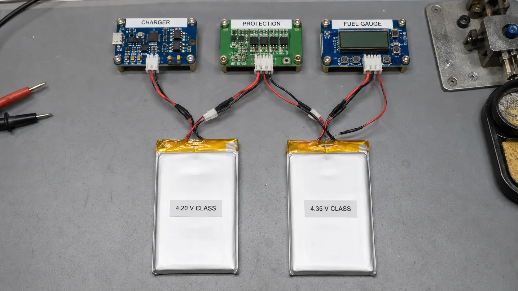

Technically Reviewed By
Dr. Maximilian Weber
Chief Scientist
Dr. Maximilian Weber is THOR Power’s Chief Scientist and a senior expert in lithium battery technology. His technical review focuses on battery safety, performance optimization, energy density and custom battery solution development.
Last technical review: September 2026

Written By
Victor Xiong
President of OEM Division & Custom Battery Specialist
Victor Xiong holds a Master’s degree from The Chinese University of Hong Kong, Shenzhen. He leads THOR Power’s OEM Division and focuses on custom battery solutions for global device brands, product developers and industrial customers.
| Written By | Technically Reviewed By |
|---|---|
| Victor Xiong President of OEM Division & Custom Battery Specialist. Victor Xiong leads THOR Power's OEM Division and focuses on custom battery development for global device brands, product developers and industrial customers. His work centers on translating replacement requests into controlled cell, charger and production decisions. | Dr. Maximilian Weber Chief Scientist. Dr. Maximilian Weber is THOR Power's Chief Scientist and a senior expert in lithium battery technology. His review for this article focuses on charger voltage, cell voltage-class boundaries, protection behavior, fuel-gauge evidence and replacement-validation risk. |
The Customer Question: Same Size, Same Connector, Higher Capacity – Can I Replace It?
A product was designed around a 1S 3.7V LiPo cell charged to 4.20V. A replacement supplier then offers a 3.8V or 3.85V pouch cell that fits the same cavity, uses the same connector and promises more capacity. From a purchasing view it looks like an upgrade. From an electrical view, it may be a different voltage class.
The compatibility question is not whether both packs are called 1S LiPo. It is whether the exact cell voltage class still matches the charger regulation voltage, protection thresholds, fuel-gauge profile, device input limits, capacity test condition and production validation evidence.
For the wider format comparison, see LiPo Battery vs. Li-ion Battery. This article focuses only on the upper charge-voltage class inside a 1S lithium battery replacement.
Quick Answer
A 4.20V-class and a 4.35V-class 1S lithium battery are not automatic substitutes. A 4.35V cell charged to 4.20V may lose the usable-energy advantage it was selected for, while a 4.20V cell charged to 4.35V can exceed its approved upper limit unless the cell maker explicitly allows it.
Fastest Buyer Check
Before approving a replacement, confirm six items: exact cell model, maximum charge voltage, charger regulation target, PCM/BMS thresholds, fuel-gauge profile and the product's maximum battery-rail voltage. If any one is unknown, the battery is not a drop-in replacement yet.
Evidence Standard
Voltage-class examples are engineering screening explanations, not universal replacement approvals. Final selection must use the exact cell datasheet, charger configuration, protection thresholds, gauge profile, production-intent samples and final-device validation.
📥 Free OEM Resource
4.2V vs 4.35V Battery Replacement Checklist
It captures the exact cell, charger target, protection limits, gauge profile, device-voltage limits and validation evidence needed for a useful engineering review.
1. Why 4.20V and 4.35V Are Different Design Classes
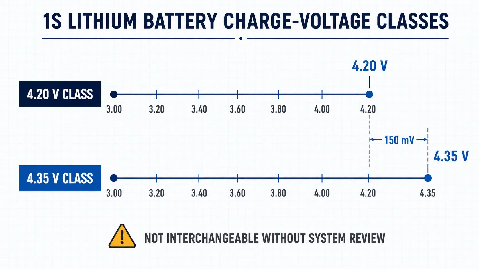
The 4.20V or 4.35V value is the cell's approved upper charge-regulation target. It is not the USB input voltage, and it is not the same thing as the nominal 3.7V, 3.8V or 3.85V printed on a label. Nominal voltage is an average representation of the discharge curve; charger approval comes from the exact cell datasheet.
A useful cross-check comes from charger and fuel-gauge vendors. TI BQ25170J exposes 4.20V and 4.35V as separate VSET choices and specifies +/-0.5% charge-voltage accuracy. TI BQ27427 provides separate preprogrammed profiles for 4.20V, 4.35V and 4.40V cells. Analog Devices LTC4124 likewise provides separate selectable charge-voltage options including 4.20V and 4.35V.
| Screening fact | Value | Engineering meaning |
|---|---|---|
| Difference between classes | 4.35V – 4.20V = 0.15V | The upper electrochemical boundary changes by design. |
| TI BQ25170J voltage accuracy | +/-0.5% | At 4.20V, +/-0.5% is about +/-21mV. The 150mV class difference is much larger than this illustrative regulation-error scale. |
| Fuel-gauge profile | 4.20V, 4.35V and 4.40V are separate profiles in TI BQ27427 | SOC estimation can be wrong even when charging hardware appears to work. |
Voltage-Class Identification Rule
Do not identify voltage class from label shorthand or one open-circuit reading: 3.7V often accompanies 4.20V cells and 3.8V or 3.85V often accompanies higher-voltage cells, but state of charge, relaxation and measurement conditions make a single voltage reading unsuitable for model identification. Use the exact cell datasheet.
2. What 4.35V May Gain – and What Must Be Revalidated
A 4.35V-class cell may be selected because the manufacturer publishes more capacity or energy within a constrained mechanical envelope. That advantage only belongs to the exact cell and the exact test conditions used to characterize it; the number cannot be carried into an existing 4.20V product unchanged.
A voltage-class change therefore triggers a fresh battery engineering review of the cell maker's charge-temperature limits, storage conditions, cycle-life test conditions, dimensional-change criteria and aging data. Do not assume that limits validated for the original 4.20V cell also apply to a 4.35V replacement.
| Decision area | Potential 4.35V advantage | Evidence needed before release |
|---|---|---|
| Usable energy | Potentially higher published Wh in the same size class. | Measure delivered Wh from the approved full-charge condition to the real device cutoff. |
| Charge compatibility | Uses the cell's intended upper charge window. | Verify charger target/tolerance, termination, recharge and charge-temperature permission against the exact cell. |
| Aging / dimensions | May meet capacity targets without enlarging the cavity. | Review the exact cell's cycle, storage and thickness-change criteria; do not inherit limits from the old cell. |
| Gauge / system behavior | Can report the intended full capacity only when the system model matches. | Verify fuel-gauge profile, battery-rail voltage limits and firmware full/empty behavior in the final product. |
No Fixed Shortcut
Do not claim that charging a 4.35V cell to 4.20V always loses a fixed percentage, or that 4.35V operation always creates a fixed cycle-life penalty. Both depend on the exact cell, charge condition, device cutoff, temperature, load and aging evidence.
3. The Two Replacement Directions Are Not Symmetric
This distinction resolves one of the most common customer confusions: undercharging a higher-voltage cell and overcharging a lower-voltage cell are not equivalent mistakes. The first may sacrifice the reason the cell was selected; the second can exceed the exact cell's approved operating limit.
| Replacement direction | What usually happens first | Engineering decision |
|---|---|---|
| 4.35V-rated cell in a product that charges to 4.20V | The cell stays below its published upper-voltage limit, but the expected capacity/energy and SOC behavior may no longer match the datasheet condition. | Potentially workable only after exact-cell charging-spec, usable-energy, gauge and device-voltage validation. Do not assume the published capacity still applies. |
| 4.20V-rated cell in a product that charges to 4.35V | The charger target exceeds the cell's published maximum charge voltage unless the manufacturer explicitly approves it. | Reject as a drop-in substitution. Do not rely on protection trips to make normal charging safe. |
4. Why a 4.35V Cell on a 4.20V Charger May Disappoint
A buyer often chooses a 4.35V-class cell because the datasheet shows more capacity in the same mechanical envelope. If the existing board still regulates at 4.20V, that headline advantage may not appear in the product.
The key mistake is estimating lost capacity from the 150mV voltage difference. Battery energy is the area under the voltage-versus-capacity curve, not simply voltage difference divided by 4.35V. A useful engineering expression is E equals the integral of V dQ over the part of the discharge curve the device can actually use.
- The cell may not reach the charge condition used for its published capacity characterization.
- The charger can still terminate normally at 4.20V, yet the user sees less runtime than expected from the new mAh label.
- A gauge calibrated for a 4.35V profile may not recognize the same full-charge state when the product intentionally stops at 4.20V.
- If firmware declares 100% from charger status rather than validated battery energy, the UI can show full while the new cell is not using its intended upper window; conversely, moving to a true 4.35V full-charge condition also requires the product battery rail and connected ICs to tolerate the higher maximum voltage.
Use the Battery Runtime Calculation Guide when the issue is usable Wh under the device load, not label mAh.
5. Why a 4.20V Cell on a 4.35V Charger Is the Red-Line Case
The reverse direction is more dangerous. A 4.20V-class cell installed into a product whose charger regulates at 4.35V is not merely receiving a more complete charge. Unless the cell documentation explicitly approves that upper voltage, the charger is trying to drive the cell beyond its specified charge limit.
This mistake can happen when a supplier matches size, connector and nominal capacity but misses the voltage class. It can also happen when an engineering team changes only the cell but leaves a resistor-set charger, PMIC register, gauge profile and production test limit unchanged.
Red-Line Rule
Do not increase a 4.20V charger to 4.35V to recover more capacity from a 4.20V-class cell. Select a cell approved for the target voltage, or keep the charger inside the original cell specification.
Not sure whether a 4.20V or 4.35V replacement is electrically safe?
Talk to a Battery Engineer6. Five Layers Must Agree After a Voltage-Class Change
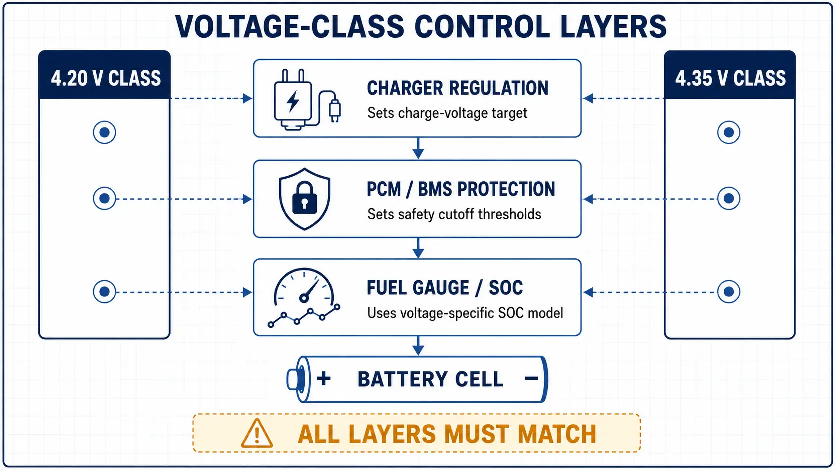
A replacement review fails when the team treats charger, protection, gauge and product electronics as interchangeable. They perform different jobs, and a voltage-class change can invalidate any one of them.
| Layer | What it controls | Typical mistake after a voltage-class change |
|---|---|---|
| Charger / PMIC | CC-CV target, charge current, termination, recharge and temperature-qualified charging. | Leaving a fixed 4.20V target when expecting 4.35V-rated capacity, or leaving 4.35V when installing a 4.20V cell. |
| PCM / BMS | Fault detection and disconnect thresholds with defined delay/release behavior. | Treating an overvoltage trip as normal full-charge termination. |
| Fuel gauge | SOC, remaining capacity and full/empty estimation using a voltage and impedance profile. | Keeping a 4.20V profile when the cell voltage curve and full-charge condition changed. |
| Device firmware / UI | Battery-low alerts, shutdown thresholds, charging UI and calibration assumptions. | Showing 100% because the charger stopped, not because delivered energy was validated. |
| Device battery rail | Normal operating range and absolute-maximum limits of battery-connected PMICs, DC/DC converters, load switches, ADCs and other direct-battery circuitry. | Reconfiguring the charger to 4.35V without checking whether the rest of the product can tolerate the higher battery rail. |
Use the Lithium Battery Charging Time Guide for CC-CV charging behavior, and the PCM/BMS Selection Guide when the replacement changes protection thresholds or recovery behavior.
Protection Is Not Regulation
A PCM/BMS overcharge threshold is a fault boundary, not the normal charger target. A battery design should not depend on fault protection to stop routine charging.
7. How to Audit an Existing Product Before Changing the Cell
If you only have the existing battery label and PCB, start there. The goal is to reconstruct the real electrical system – not just identify a battery that fits.
| Question | Evidence to obtain | Why the customer needs it |
|---|---|---|
| 1. What exact cell is installed? | Manufacturer/model, datasheet, maximum charge voltage and allowed charge-temperature range. | Prevents 3.7V/3.8V label shorthand from becoming the specification. |
| 2. What does the charger really regulate to? | Charger IC part number plus resistor/register configuration, confirmed by a controlled charge trace. | Separates USB/input voltage from the actual cell charge target. |
| 3. What are the protection limits? | PCM/BMS overcharge, overdischarge, overcurrent, delay and release behavior. | Avoids treating a protection threshold as a normal operating target. |
| 4. What profile does the gauge use? | Gauge IC, chemistry/profile, learned capacity and firmware assumptions. | Prevents wrong SOC or full/empty reporting after the voltage-class change. |
| 5. Can the product tolerate the new full-charge voltage? | Battery-connected IC operating ranges/absolute maximums, plus the actual battery-to-system power path. | Prevents a charger-compatible 4.35V change from overstressing downstream electronics. |
| 6. What does the product actually need? | Load waveform, runtime target, cutoff voltage, temperature range, enclosure and market scope. | Ties the replacement decision to real usable energy and operating conditions, not label mAh. |
Download the 4.2V vs 4.35V Battery Replacement Checklist before requesting a replacement quotation. It captures the exact cell, charger target, protection limits, gauge profile, device-voltage limits and validation evidence needed for a useful engineering review.
8. Three Engineering Cases
Case 1: Higher-Capacity 4.35V Cell, Almost No Runtime Gain
Project situation: A wearable device replaced a 4.20V-class pouch cell with a 4.35V-class pouch cell of similar size.
Hidden risk: The charger still stopped at 4.20V, and the published capacity advantage was tied to a higher charge condition.
Engineering response: The team confirmed that the production charger terminated at 4.20V, then measured a full charge/discharge trace to the same device cutoff and compared delivered Wh instead of label mAh.
Buyer lesson: Operating a 4.35V-rated cell with a 4.20V charge ceiling may keep the cell below its published upper-voltage limit, but compatibility still depends on the exact charging specification, usable-energy target and gauge behavior.
Case 2: A Late 4.20V Substitute Looked Fine Until Near Full Charge
Project situation: A supplier proposed a 4.20V-rated substitute for a product whose board had been configured for a 4.35V cell.
Hidden risk: Initial fit, connector and low-SOC function looked acceptable, but full-charge voltage exceeded the replacement cell's upper limit.
Engineering response: The team verified the board's 4.35V charger regulation target at the battery terminals, rejected the lower-voltage substitute as a drop-in change and moved the project to a controlled redesign review.
Buyer lesson: Compatibility must be checked at the top of charge, not only at power-on or mid-SOC.
Case 3: Charger Correct, Battery Percentage Wrong
Project situation: The charger was reconfigured correctly for the new voltage class, but customer testing reported unstable battery percentage.
Hidden risk: The fuel gauge profile and firmware full/empty assumptions still matched the old voltage curve.
Engineering response: The team compared gauge-reported SOC with measured discharged energy through a controlled full-charge-to-device-cutoff cycle, then corrected the gauge/profile and full/empty definitions.
Buyer lesson: Changing voltage class is an electrical-system change, not only a charger setting change.
9. Four Evidence Checks Before Production Approval
| Approval check | What to test | Release evidence |
|---|---|---|
| Charge boundary | Controlled full charge with production charger; log cell-terminal voltage, net battery current, NTC and termination. | Peak voltage and termination remain inside the exact cell specification without protection trips. |
| Usable energy | Start from the approved full-charge condition and run the real device load to its actual cutoff. | Delivered Wh/runtime meet the target; no assumed gain or loss from 150mV alone. |
| Control coordination | Verify PCM/BMS thresholds, gauge profile, device battery-rail limits, firmware UI and low-battery behavior. | Charger, protection, device electronics and SOC reporting all agree with the selected cell class. |
| Production repeatability | Build pilot units with production cells, connectors, PCM/BMS and charger settings. | Voltage, capacity, protection behavior and traceability remain consistent without hand adjustment. |
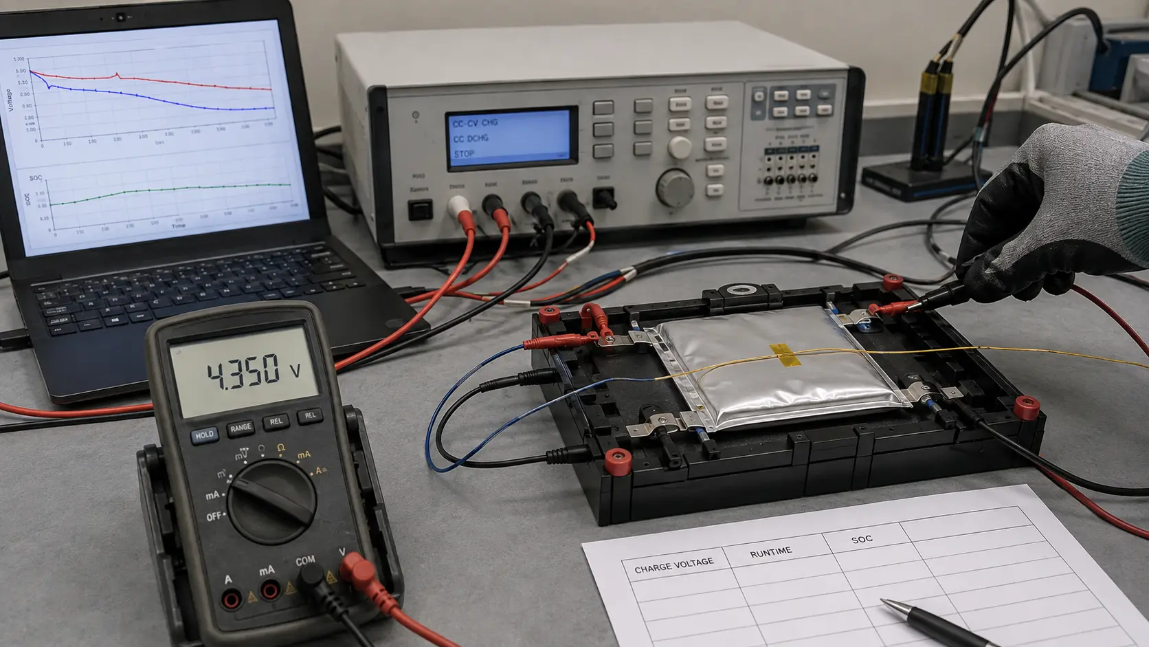
For sample-stage evidence, connect this review to the Battery Pack Prototype Testing Guide. For replacement projects using pouch cells, review Custom LiPo Battery Models as a starting point, then validate the exact voltage class.
10. What to Send THOR Power for a Replacement Review
Send the current battery label/model, exact cell datasheet if available, charger IC and settings, PCM/BMS limits, fuel-gauge profile, battery-rail voltage limits, runtime target, connector/NTC details, product cavity information and target markets.
THOR Power can then determine whether the change is a true drop-in replacement, a charger/gauge update, a protection or device-power-path change, or a full battery-system redesign.
For a project-specific review, use THOR Power Custom Solutions.
11. Final Approval Rule
Release the Electrical System, Not the Label
Approve the exact cell together with its charger target, PCM/BMS thresholds, fuel-gauge profile, device battery-rail limits, firmware behavior, usable-energy evidence and production traceability. Do not approve a 4.20V or 4.35V replacement from size, connector and mAh alone.
Planning a 4.20V or 4.35V LiPo Replacement?
Share the current battery model, charger IC and settings, PCM/BMS limits, fuel-gauge profile, device battery-rail limits, connector, NTC, runtime target and target market. THOR Power can review whether the project needs a 4.20V- or 4.35V-class cell, charger or gauge reconfiguration, revised protection limits, production-intent samples or full replacement validation.
12. Key Takeaways
- 4.20V and 4.35V are upper charge-voltage classes, not interchangeable label details.
- A 4.35V-rated cell on a 4.20V charger may be electrically possible but can lose expected usable energy and gauge accuracy.
- A 4.20V-rated cell on a 4.35V charger is a red-line substitution unless the exact cell maker explicitly approves that voltage.
- Charger regulation, PCM/BMS protection, fuel-gauge estimation, device battery-rail limits and firmware behavior are separate control layers.
- Do not predict capacity gain or loss from the 150mV difference alone; measure delivered Wh under the real device load.
- Release the exact electrical system and production process, not only the battery label, size and connector.
13. Conclusion
A 4.35V lithium battery is not simply a better 4.2V battery, and a 4.2V lithium battery is not simply a cheaper substitute. They can belong to different cell design classes with different upper charge limits, charger settings, gauge profiles and validation boundaries.
The safe replacement decision is practical: identify the exact cell, prove the charger target, verify the protection and fuel gauge, measure usable energy in the final product and control the shipped configuration. If those checks are not complete, the replacement is still an engineering change, not a drop-in battery.
14. FAQ: 4.2V vs 4.35V Lithium Battery
FAQ: 4.2V vs 4.35V Lithium Battery
Is a 4.35V lithium battery the same as a 4.2V battery?
No. They may both be 1S lithium batteries, but 4.20V and 4.35V refer to different approved upper charge-voltage targets. The exact cell datasheet decides the allowed maximum voltage.
Can I charge a 4.35V battery with a 4.2V charger?
Sometimes it can be electrically acceptable if the cell allows operation below 4.35V, but the battery may not deliver the published capacity or expected runtime. Validate usable energy and gauge behavior.
Can I charge a 4.2V battery with a 4.35V charger?
Do not treat this as a drop-in substitution. Unless the exact cell maker explicitly approves 4.35V charging, the charger target exceeds the cell's specified upper limit.
Does 3.7V always mean 4.2V and 3.8V always mean 4.35V?
No. Nominal voltage is shorthand for the discharge curve and label class. Use the exact cell datasheet to confirm maximum charge voltage.
Will a 4.35V battery always give more runtime?
No. Extra runtime depends on the exact cell, charger target, device cutoff, voltage curve, temperature and load. A 4.35V cell charged only to 4.20V may not show the expected advantage.
Is PCM/BMS overcharge protection enough to make the charger safe?
No. Protection is a fault boundary. Normal charging should be controlled by the charger regulation target, current, temperature permissions and termination behavior.
Do I need to change the fuel gauge when changing from 4.2V to 4.35V?
Often yes. A gauge profile built for one voltage curve can report incorrect SOC, full capacity or low-battery behavior after a voltage-class change.
What should I test before approving a 4.35V replacement cell?
Test charger regulation, peak cell voltage, termination, NTC behavior, usable Wh/runtime, protection thresholds, fuel-gauge reporting and pilot-unit consistency using production-intent samples.
Do I need to check the product electronics if full-charge voltage increases to 4.35V?
Yes. Verify the normal operating range and absolute-maximum limits of any circuitry connected to the battery rail, including PMICs, converters, load switches and ADC inputs. Charger compatibility alone does not prove device compatibility.
What information should I send for a 4.2V vs 4.35V review?
Send the current battery label/model, exact cell datasheet if available, charger IC and settings, PCM/BMS limits, fuel gauge profile, product load, runtime target, connector, NTC and target markets.
Technical References
- Texas Instruments – BQ25170J 1-cell charger. Official product page showing selectable Li-ion VSET options including 4.20V, 4.35V and 4.40V, plus +/-0.5% charge-voltage accuracy.
- Texas Instruments – BQ27427 single-cell fuel gauge. Official product page showing selectable preprogrammed profiles for 4.20V, 4.35V and 4.40V cells.
- Analog Devices – LTC4124 wireless Li-ion charger. Official product page showing pin-selectable charge-voltage options including 4.20V and 4.35V.
- IEC 62133-2:2017+A1:2021. Safety requirements and tests for portable sealed secondary lithium cells and batteries within its scope.
- IEC 61960-3:2017. Performance tests, designations, markings, dimensions and other requirements for portable secondary lithium cells and batteries within its scope.
- UNECE – UN Manual of Tests and Criteria, Revision 8 (2023) and Amendment 1 (2025). Official dangerous-goods framework including lithium-cell and battery transport testing under subsection 38.3.


Dr. Maximilian Weber is THOR Power's Chief Scientist and a senior expert in lithium battery technology. His technical review focuses on battery safety, performance optimization, energy density and custom battery solution development.
Last technical review: September 2026

Victor Xiong holds a Master's degree from The Chinese University of Hong Kong, Shenzhen. He leads THOR Power's OEM Division and focuses on custom battery solutions for global device brands, product developers and industrial customers.