
Battery Pack Thermal Management Guide: Heat Sources, Hotspots, Sensor Placement and Validation

Technically Reviewed By
Dr. Maximilian Weber
Chief Scientist
Dr. Maximilian Weber is THOR Power’s Chief Scientist and a senior expert in lithium battery technology. His technical review focuses on battery safety, performance optimization, energy density and custom battery solution development.
Last technical review: September 2026

Written By
Victor Xiong
President of OEM Division & Custom Battery Specialist
Victor Xiong holds a Master’s degree from The Chinese University of Hong Kong, Shenzhen. He leads THOR Power’s OEM Division and focuses on custom battery solutions for global device brands, product developers and industrial customers.
| Written By | Technically Reviewed By |
|---|---|
| Victor Xiong President of OEM Division & Custom Battery Specialist. Victor Xiong leads THOR Power‘s OEM Division and focuses on custom battery development for global device brands, product developers and industrial customers. | Dr. Maximilian Weber Chief Scientist. Dr. Weber’s technical review for this article focuses on heat-source identification, electro-thermal behavior, sensor placement, enclosure heat transfer, thermal-control boundaries, production-intent validation, pilot-production variation and the distinction between normal thermal management and thermal-runaway propagation evidence. |
Before choosing a cooling method, an OEM team should define the real duty cycle, temperature limits, heat sources, heat-transfer path and production evidence required by the final product. This guide builds on the Custom Battery Pack Design Guide as the parent workflow and helps product teams avoid mistaking a short bench test or one maximum-temperature reading for complete thermal approval. Non-standard enclosure or cooling projects can be scoped through a custom battery engineering review.
The battery prototype completed a short room-temperature load test with the enclosure open. After installation in the sealed product, the fourth repeated duty cycle caused a thermal shutdown. The first proposal was a larger cell. Synchronized measurements later showed that the cells were not the first limiting component: heat was concentrated in the BMS current path and one connector termination, while a nearby converter warmed the trapped air around the pack.
The supplier said the battery had passed thermal testing. The customer said the product overheated. Both statements were true because the two teams had tested different thermal systems. One tested a loose pack for a short period; the other operated a complete product long enough for local electrical loss and enclosure heat soak to interact.
Quick Answer
Battery-pack thermal management begins by defining the real duty cycle and temperature limits, locating every important heat source, mapping a complete heat-transfer path, placing sensors where they represent the limiting risks, coordinating normal control with derating and emergency protection, and validating the production-intent battery in the final product through repeated operation and pilot production. Cell temperature alone is not sufficient evidence.
Four Thermal Approval Questions
1. Did the test represent the worst credible load, ambient, enclosure and life condition? 2. Were the limiting cells, current-path components and external heat sources actually measured? 3. Did the sensor and control logic act early enough to keep every component inside its approved boundary? 4. Can normal production repeat the validated heat path, sensor placement and material stack-up?
Case Transparency Note
The engineering cases in this article are representative composite scenarios based on recurring battery-project patterns. They explain diagnostic and approval decisions without identifying a specific customer or presenting confidential project data as a named THOR Power case study.
📥 Free OEM Resource
Battery Pack Thermal Review Checklist
Prepare enclosure, load, sensor, temperature-limit and validation evidence before requesting a thermal review.
1. Thermal Approval Is Not One Maximum-Temperature Reading
A single temperature number can be useful, but it does not identify what was heated, where the sensor was placed, how long the test ran, whether the product reached thermal steady state, or whether production variation was represented. Thermal approval is a chain of evidence linking the requirement, physical configuration, electrical load, sensor locations, control response and manufacturing process.
- A short open-bench test shows how one sample behaves under favorable heat-rejection conditions.
- Integrated thermal validation shows whether the production-intent battery works with the real enclosure, charger, firmware, load and environment.
- Production validation shows whether normal manufacturing can repeat the approved heat generation, heat-transfer path and sensor installation.
NREL thermal-management guidance treats both average pack temperature and temperature uniformity as design objectives and emphasizes the use of analysis together with experimental validation. The same principle applies beyond electric vehicles: a compact pouch-cell product, a high-current cylindrical pack and a stationary LiFePO4 module need different cooling architectures, but all require a defined thermal objective and evidence from the complete assembly.
Core Engineering Principle
Do not begin with “Which cooling material should we add?” Begin with “What is the worst credible heat load, where is it generated, which temperature boundary will be reached first, how will heat leave, and how will the approved result be repeated in production?”
2. Why the Open-Bench Battery Often Creates False Confidence
An uncovered pack benefits from free convection, direct radiation to the room and heat spreading through test fixtures. The final product may remove airflow, surround the pack with foam, add a display or converter as a second heat source, restrict wire routing and warm the same trapped air on every duty cycle. Electrical behavior may stabilize within seconds while cells, internal air, enclosure walls and thermal interfaces keep warming for tens of minutes or longer.
- Testing only the first load cycle when later cycles reveal enclosure heat accumulation.
- Measuring one accessible cell while the BMS, fuse, connector or center cell group is hotter.
- Using nominal current instead of the higher low-voltage current of a constant-power load.
- Approving the battery in free air while final foam, sealing, compression and nearby electronics change the heat path.
- Testing a fresh hand-built sample without representing aged resistance or pilot-production variation.
Composite Engineering Case 1 — The Enclosure Created the Failure
Project situation: A compact monitoring device completed one high-load cycle with the cover removed.
Hidden risk: Inside the sealed product, trapped heat from the BMS and a nearby converter accumulated over repeated cycles. The existing NTC followed one outer cell and missed the earlier board hotspot.
Engineering response: The team synchronized current, voltage and temperatures at the outer cell, center cell, BMS power stage, connector and enclosure, then revised the current path, sensor plan and conduction path to the housing.
Buyer lesson: A battery that passes in free air is not approved for a sealed enclosure. The final device and repeated duty cycle define the thermal system.
3. Define What Each Thermal Validation Stage Must Prove
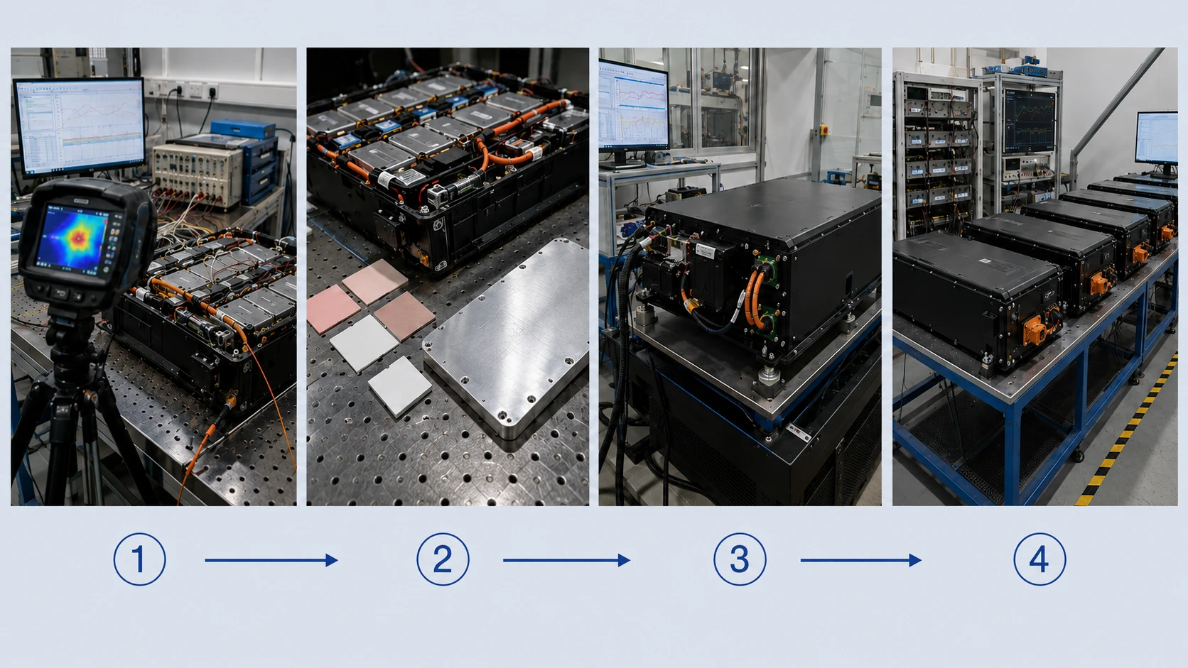
Project teams may use EVT, DVT and PVT labels, but those names are not universal thermal standards. The approval record should state what the sample must prove, which parts and materials are production-intent and what the stage cannot approve.
| Thermal stage | Question it should answer | Expected construction | What it should not approve |
|---|---|---|---|
| Concept screening | Where are likely heat sources and cooling constraints? | Early cells, estimated losses, simplified enclosure or model. | Final sensor positions, lifetime, certification or production. |
| Engineering thermal sample | Does the proposed heat path and control concept work? | Correct cell family and topology; temporary probes or interfaces may remain. | Final enclosure, material tolerance or mass-production consistency. |
| Integrated design validation | Does the battery work with the actual device, charger, firmware and enclosure? | Near-final cells, BMS, connector, sensors, materials and mounting. | Production repeatability unless intended processes are represented. |
| Production-intent validation | Does the frozen design meet the thermal requirement? | Final BOM, firmware, drawings, material stack-up and representative tolerances. | Normal production variation until a pilot lot is reviewed. |
| Pilot or production validation | Can normal manufacturing repeat the approved result? | Intended tools, operators, materials, inspections and final test. | Future design or supplier changes without controlled revalidation. |
4. Seven-Step Battery Thermal Design and Approval Workflow
The workflow below converts an overheating complaint or early thermal concept into a controlled production decision. A project should advance only when the required evidence is complete or the remaining deviation is formally accepted.
| Step | Engineering decision | Release evidence |
|---|---|---|
| 1 — Freeze the thermal requirement | Define loads, ambient, enclosure, limits, gradients, control actions, life condition and applicable standards. | Approved thermal requirement matrix with sensor locations and pass/fail rules. |
| 2 — Record the as-built configuration | Identify cells, lot, BMS/firmware, current path, connector, wire, sensors, materials, enclosure and deviations. | Traceable sample ID, build record, photographs and thermal stack-up. |
| 3 — Map heat generation | Quantify cell and current-path losses for charge, discharge, pulses, standby, balancing and nearby electronics. | Heat-source map linked to current, voltage drop and component ratings. |
| 4 — Design heat paths and sensor coverage | Select interfaces, spreaders, airflow/coolant and sensor locations from the risk map. | Controlled drawings, material specifications and measurement-error budget. |
| 5 — Validate the final device | Test repeated duty, charging, temperature range, low SOC, warm restart and control response in the enclosure. | Synchronized raw electrical/thermal data and requirement-linked results. |
| 6 — Review pilot-production variation | Sample normal material, assembly pressure, sensor attachment, resistance and final-test variation. | Pilot-lot thermal results and critical-to-quality controls. |
| 7 — Approve release and change control | Freeze the validated configuration and define changes that trigger review or retest. | Signed release package, retained references, controlled BOM/drawings and change matrix. |
Phrases such as “must not get hot,” “works in summer” and “BMS protects the cells” are not testable requirements. The thermal requirement should define the exact chemistry and charge profile; the full current waveform with duration, repetition and simultaneous charge-and-use states; the ambient, solar and cold/warm-start range; the enclosure material, sealing, orientation and available air volume; the allowable temperatures for cells, BMS semiconductors, fuse, connector, wire insulation, plastics and external surfaces; allowable cell-to-cell gradients; the normal-control, derating and emergency-protection actions; and the beginning-of-life, end-of-life and production-tolerance conditions with pre-agreed sensor accuracy.
Requirement Warning
Do not let the supplier redefine the thermal limit, move the sensor or shorten the run after seeing the result. Limits, measurement locations, stabilization criteria and allowed control actions should be agreed before the test. Otherwise a failed sample can be made to “pass” without closing the underlying risk.
5. Gate 1: Map Every Heat Source, Not Only the Cells
The cells are one heat source. Welds, busbars, BMS MOSFETs, shunts, fuses, contactors, wires, crimps, connectors, chargers and nearby electronics can create equally important local losses. Build a heat-source map for charging, continuous discharge, peak load, standby, balancing, precharge and fault-clearing conditions. The complete current-path resistance that drives much of this heat is covered in the Connector, Wire Gauge and NTC Selection Guide.
Resistive Heat Screening
For first-pass screening, resistive heat in a path can be estimated as Ploss = I²R. It is not a complete electrochemical heat model: cell heat also depends on chemistry, temperature, state of charge, rate, pulse duration, reversible heat and aging. Example: a 20 A path with 8 mΩ produces about 3.2 W; if aging or a poor crimp raises it to 12 mΩ, heat rises to about 4.8 W — a 50% increase with no change in capacity or load current. Use a four-wire Kelvin method for milliohm-level measurements.
| Potential heat source | Evidence to collect | Common reason it is missed |
|---|---|---|
| Cell or parallel group | Representative center/edge surface temperatures, loaded voltage and current sharing where possible. | Only average pack current or one external case temperature is reviewed. |
| Weld, tab, nickel or busbar | Joint resistance, voltage drop, local temperature and current sharing. | A small defect becomes visible only during peak or repeated load. |
| BMS MOSFETs and PCB copper | Board temperature, conduction loss, copper spreading and enclosure contact. | The advertised BMS current is treated as a thermal guarantee. |
| Shunt, fuse, contactor or precharge path | Voltage drop, time-current duty, switching sequence and local temperature. | Protection components are considered only during faults. |
| Wire, crimp and connector | Loop resistance, aged contact resistance, termination temperature and loaded device voltage. | Wire gauge or connector catalog current is reviewed without the finished assembly. |
| Adjacent charger, converter or motor driver | Temperature and heat flux into the battery zone during operation and charging. | Battery heat is assumed to be self-generated. |
Composite Engineering Case 2 — The Hottest Point Was Not the Cell
Project situation: A cylindrical-cell pack repeatedly entered high-temperature protection during a motor duty cycle.
Hidden risk: Cell surfaces were warm but below the proposed limit. The mated connector, one crimp and the BMS switching region created concentrated I²R loss.
Engineering response: The team measured voltage drop and temperature across the complete path, changed the terminal/contact and crimp controls, then repeated the closed-enclosure test at low state of charge.
Buyer lesson: Increasing capacity or selecting a higher-current BMS label would not have corrected the local resistance that created the hotspot.
6. Gate 2: Separate Local Hotspots From Pack-Level Heat Accumulation
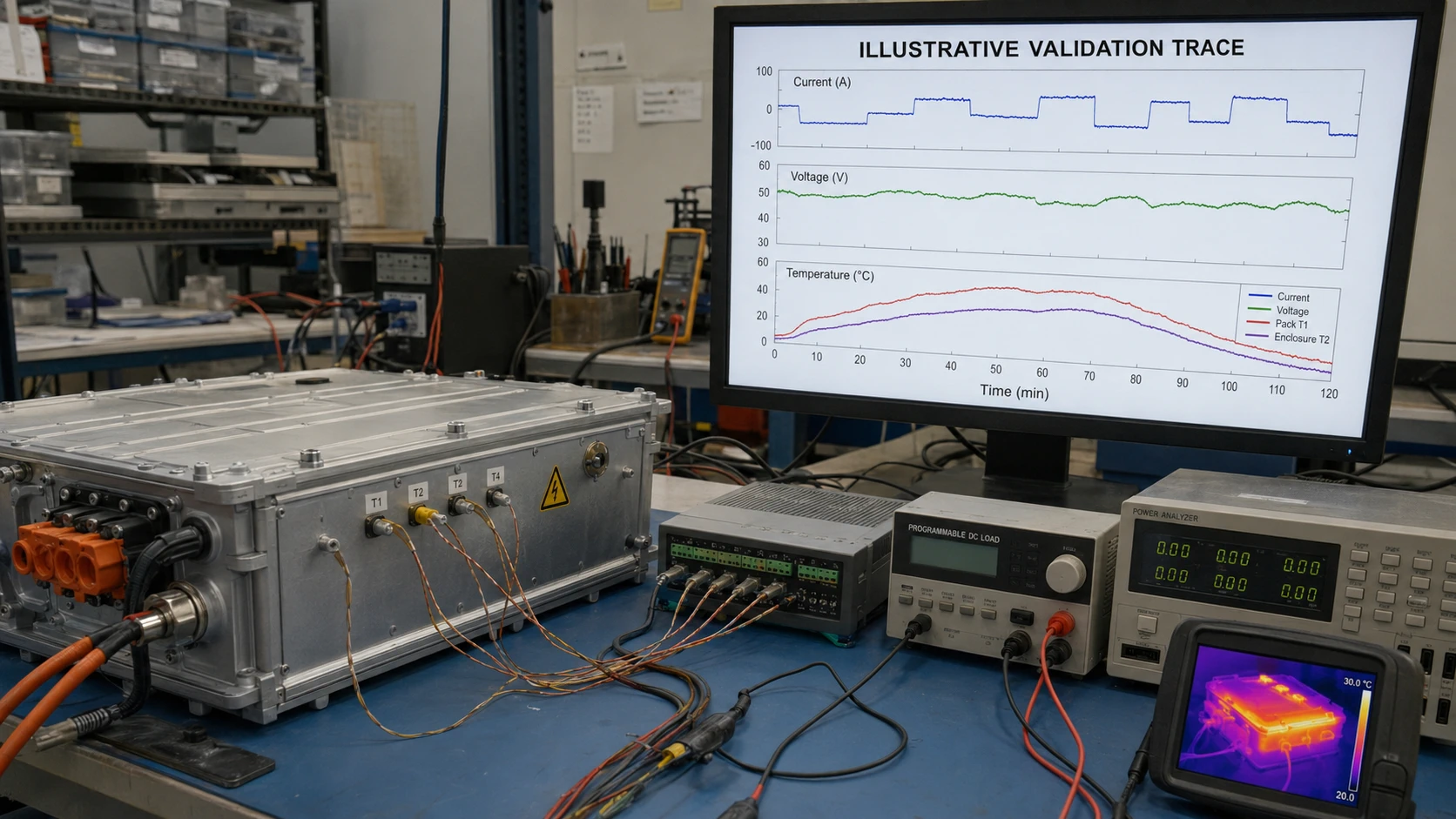
A local hotspot is a concentrated source such as a connector, MOSFET, weld or center cell group. Pack-level heat accumulation is the gradual warming of the complete assembly because heat cannot leave as fast as it is generated. The two problems can occur together, but they require different measurements and corrections. Record current, voltage, temperatures, charger state, BMS state and control commands against one time base. A rapid local rise aligned with a current pulse suggests concentrated electrical loss. A slow rise across many locations over repeated cycles suggests stored heat and restricted rejection. A delayed temperature rise after the load stops may show heat moving from an internal source toward an external sensor.
Measurement Warning
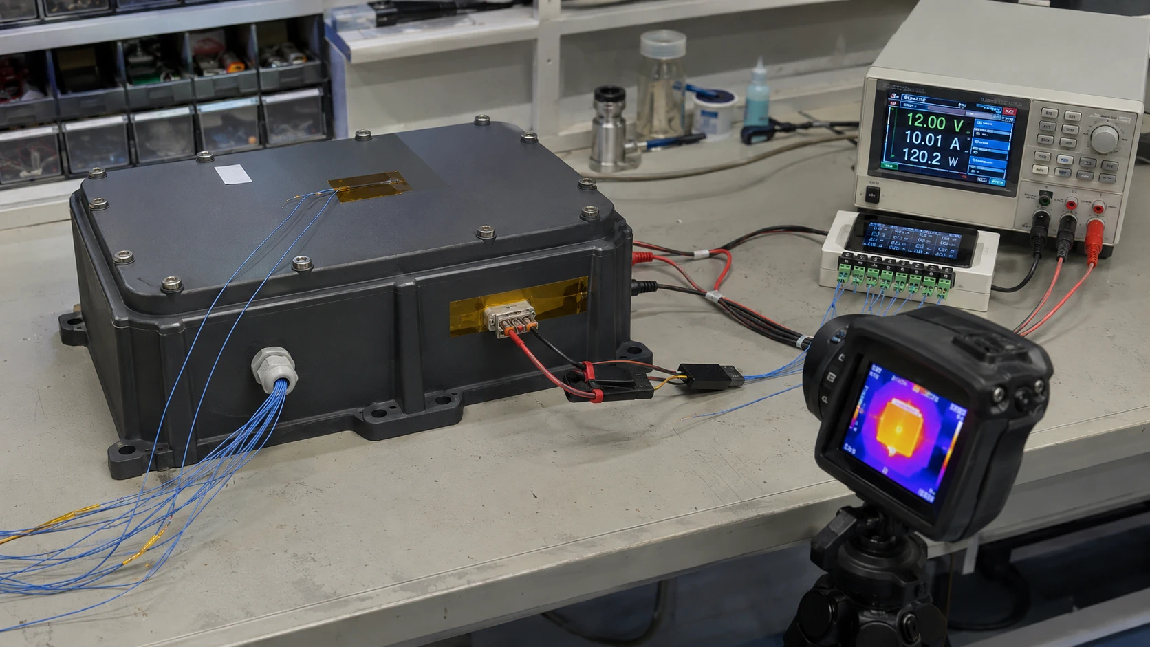
An infrared image can reveal visible surface hotspots, but it does not show hidden interfaces, internal cell temperature or accurate temperature on reflective metal without emissivity control. Use thermal imaging together with contact sensors, electrical measurements and a documented line of sight; do not treat one thermal image as a complete approval record.
7. Gate 3: Build a Complete Heat-Transfer Path
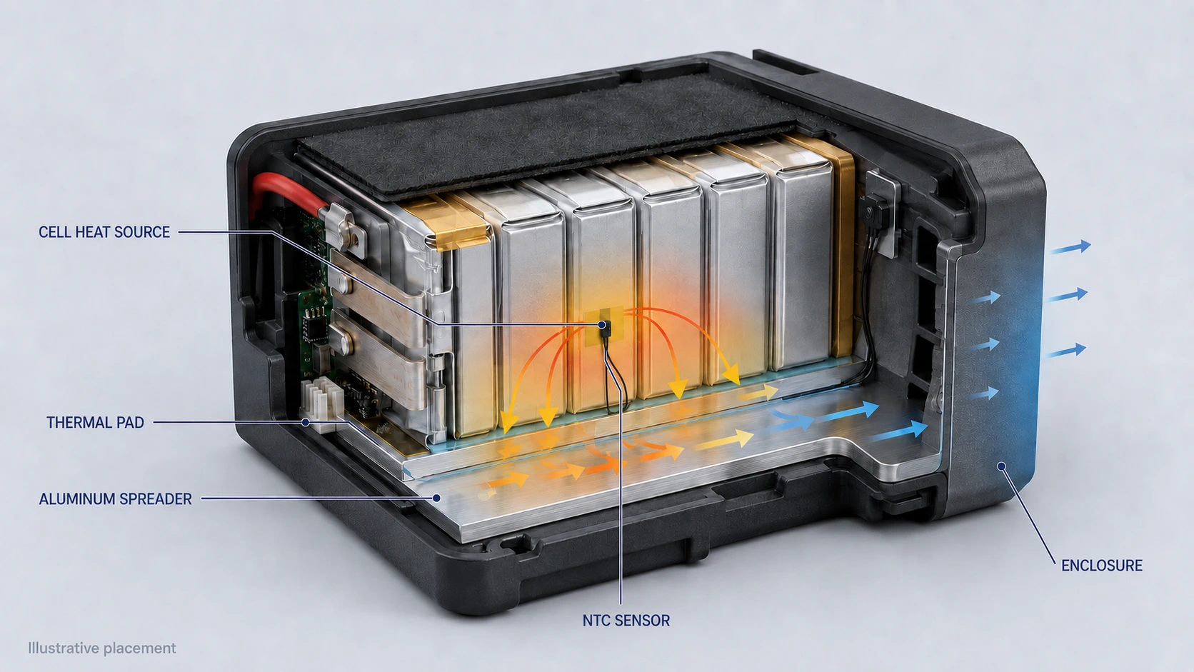
A pad, plate, fan or coolant loop is useful only when it connects a real source to a sink that can reject the heat. Map the path as source → interface → spreader, structure, air or coolant → external environment. Review every gap, contact pressure, insulation layer and downstream temperature. A screening estimate such as ΔT ≈ heat load × thermal resistance can support comparison only when boundary conditions are unchanged. Final approval requires measurement or a validated model of the actual geometry, materials, contact conditions and duty cycle.
| Method | Useful when | Engineering cost or hidden trade-off |
|---|---|---|
| Cell spacing and layout | Reducing cell-to-cell coupling, separating sources or creating a defined air path. | Consumes volume and can change mechanical support or current-path length. |
| Thermal pad or gap filler | Coupling a known hotspot to a spreader across a controlled gap. | Thickness, compression, insulation, pump-out and long-term stability must be validated. |
| Metal spreader or housing | Distributing a local heat flux over a larger surface. | Adds mass and can create insulation, abrasion, condensation or touch-temperature concerns. |
| Natural convection | Low or moderate heat load with a genuine inlet/outlet or external surface path. | Performance falls in sealed, dusty, cramped or high-altitude conditions. |
| Forced air | Repeated or continuous load with a controlled airflow route. | Fan power, noise, blockage, dust, bearing life and single-fault behavior become requirements. |
| Potting or encapsulation | Mechanical retention, ingress control and sometimes conduction to a housing. | Can trap heat, create cure stress, add mass and prevent service if material or geometry is wrong. |
| Low-temperature heater | Preheating cells before charge or high-power use in cold conditions. | Consumes energy and requires sensor plausibility, timeout and fault control. |
| Liquid cooling | High heat flux or strict uniformity in larger systems. | Adds pumps, seals, leak detection, controls, service and qualification complexity. |
Before adding a thermal pad, ask whether it touches the true hotspot under tolerance and vibration, whether its compression is safe for pouch cells and solder joints, whether it preserves electrical insulation, and where the heat goes after it reaches the plate. A path that ends at an already hot or insulated surface is not a heat-rejection solution.
8. Gate 4: Place Temperature Sensors From the Risk Map
Sensor placement should follow the limiting risk, thermal lag and consequence of a missed event. The easiest wire-routing position is not automatically the correct measurement position. A small single-cell LiPo pack may use one well-coupled NTC when gradients are limited and validated. A larger multi-series or high-power pack may require separate sensing for cell groups, the BMS power stage, connector, coolant or enclosure. Thermistor monitoring depends not only on the thermistor but also on bias resistance, ADC resolution and other circuit errors; in the finished product, attachment pressure, insulation, adhesive, wire routing and location add further uncertainty. Sensor-channel and threshold coordination is covered in the PCM/BMS Selection Guide.
| Sensor question | Approval evidence | Failure when ignored |
|---|---|---|
| What does the sensor represent? | Explicitly name cell surface, inter-cell region, BMS hotspot, connector, coolant or ambient. | The system protects an easy-to-reach point rather than the limiting component. |
| How quickly must it respond? | Installed step-response or representative heat-pulse test. | Thermal lag allows the protected part to exceed its limit before control reacts. |
| How is contact maintained? | Controlled adhesive, tape, clip, pad pressure or fixture and installation drawing. | The sensor lifts, moves or measures trapped air after vibration or aging. |
| What if the channel opens or shorts? | Diagnostic range, fault code and safe charge/discharge response. | A failed sensor is interpreted as a plausible temperature. |
| What is the total measurement error? | NTC curve/tolerance, pull-up, ADC, wiring, calibration and sampling budget. | The threshold is placed closer to the real limit than the measurement uncertainty permits. |
| Which production variables matter? | Sensor part, placement tolerance, adhesive, contact pressure and final-test check. | The approved prototype location is not repeated in mass production. |
Composite Engineering Case 3 — The Sensor Reported a Safe Pack
Project situation: A pack logged acceptable cell temperature during repeated high-current operation, yet one connector housing showed heat damage.
Hidden risk: The only NTC was attached to an outer cell. It was never intended to detect a local contact-resistance fault several centimeters away.
Engineering response: The design reduced contact resistance, added targeted connector-temperature validation and retained cell sensing for charge/discharge limits. The team did not raise the cell-temperature threshold to accommodate the unmeasured hotspot.
Buyer lesson: A sensor can only control the condition it measures. Prevent local interface faults through component and process control, then validate them with appropriate instrumentation.
9. Gate 5: Coordinate Normal Control, Derating and Emergency Protection
A BMS temperature trip is an emergency boundary, not a substitute for normal thermal control. The charger, host firmware, fan, pump or heater should maintain normal operation inside the validated region; derating should reduce stress before a limit is crossed; protection should interrupt abnormal operation and define recovery.
| Control layer | Purpose | Typical actions |
|---|---|---|
| Normal operating control | Maintain performance and life inside the intended region. | Charge-current scheduling, load management, fan/pump control, heater control and balanced airflow. |
| Derating | Prevent a predictable approach to a component or cell boundary. | Reduce charge current, motor torque, inverter power, pulse repetition or nonessential loads. |
| Emergency protection | Interrupt operation after an abnormal boundary or sensor fault. | BMS charge/discharge cutoff, contactor opening, latched fault, controlled recovery and logging. |
Charge and discharge temperature limits may differ, and different components may need different thresholds. Hysteresis, delay and recovery should prevent rapid cycling without hiding a persistent defect. Normal charging should not terminate by repeatedly hitting overtemperature protection, and normal product operation should not depend on emergency cutoff to manage predictable heat.
Composite Engineering Case 4 — Protection Worked but the Product Failed
Project situation: A sealed device repeatedly reached BMS overtemperature cutoff near the end of a long duty cycle.
Hidden risk: The emergency cutoff prevented further heating, but the product lost data and restarted immediately after the sensor cooled, producing repeated thermal cycling.
Engineering response: The team introduced staged load derating, preserved an orderly shutdown window, revised recovery timing and validated the sequence through warm restart and repeated cycles.
Buyer lesson: A successful protection trip does not prove acceptable product behavior. Thermal control, derating, shutdown and recovery must be approved as one system.
10. Gate 6: Resolve Mechanical, Sealing and Environmental Conflicts
Thermal, mechanical, ingress and electrical requirements often work against one another. A higher IP target can remove vents and trap heat. Anti-vibration foam can block a useful conduction surface. Potting can improve retention or conduct heat to a metal case, but an unsuitable compound or trapped void can create a barrier. A metal bracket can spread heat while abrading insulation or concentrating pressure on a pouch cell.
- Validate thermal-interface thickness and compression across tolerance, swelling, vibration and material aging.
- Confirm that required creepage, clearance and electrical insulation remain intact after adding spreaders or conductive materials.
- Check condensation, coolant leakage, dust blockage, fan failure and installation against insulating surfaces where relevant.
- Include external surface and user-touch temperatures when the enclosure itself becomes the heat-rejection path.
- Do not assume waterproofing, potting or metal construction automatically improves battery thermal performance.
Composite Engineering Case 5 — Acceptable Average Temperature, Unacceptable Gradient
Project situation: A LiFePO4 backup module met its proposed average-temperature target during a room-temperature discharge.
Hidden risk: Center groups were insulated by the pack geometry while outer groups coupled to the metal enclosure. The average concealed a persistent internal gradient.
Engineering response: The team added center and edge sensors, revised the spreading path and changed acceptance criteria to include both maximum temperature and group-to-group difference.
Buyer lesson: Average pack temperature cannot approve a design when one region determines aging, cutoff or usable capacity.
11. Gate 7: Separate Normal Thermal Management From Thermal-Runaway Propagation
Routine thermal management addresses normal charging, discharging, ambient exposure, temperature uniformity, performance, life and control behavior. Thermal-runaway propagation assessment begins after a severe cell-level failure and asks whether heat, gas, flame, pressure or ejecta cause adjacent cells, modules, the enclosure or nearby systems to fail. NASA tested a flight-like International Space Station battery enclosure, cooling features, barriers, venting and instrumentation under a deliberately initiated cell failure; that tested configuration did not propagate to the adjacent live cells. The lesson is not that a particular spacing or shield works universally. It is that containment must be demonstrated on the actual architecture and defined failure scenario. For the system-level failure-mechanism discussion, see the lithium-ion battery safety guide.
Scope Warning
Do not present UN 38.3, IEC 62133-2, IEC 62619, UL 1973 or UL 9540A as proof that a finished product will meet its normal operating temperature, runtime or enclosure heat-rise target. Transport testing, battery safety standards, thermal-runaway fire testing and application-specific thermal validation answer different questions.
12. Gate 8: Validate the Production-Intent Battery in the Final Product
Thermal approval belongs to the production-intent battery in the actual host product. Testing should use the final or controlled cells, BMS hardware and firmware, welds, fuse, connector, wire, sensors, thermal materials, enclosure, charger and device firmware. Current, voltage, temperature, BMS state and control commands should share a common time base. Instrument the risk locations: representative center and edge cells, BMS MOSFET or power-stage region, shunt, fuse, connector termination, critical crimp, coolant or airflow points, nearby electronics and external surfaces. Worst credible conditions may include maximum ambient, warm restart, low-SOC constant-power current, cold high-resistance start, repeated pulses, charge-while-use, blocked airflow, aged fan, reduced interface pressure, end-of-life cell resistance and production component variation. The worst condition is not always the hottest room; it is the combination that creates the greatest heat generation or weakest heat rejection. The Battery Runtime Calculation Guide explains why low-SOC current can be higher than the convenient test point.
| Validation area | Representative scope | Approval evidence | Typical owner |
|---|---|---|---|
| Configuration | Cell lot, topology, BMS/firmware, current path, sensors, materials and enclosure. | Build record, photos, sample ID and deviations. | Supplier + OEM |
| Heat generation | Cell loss, BMS, welds, fuse, connector, wire and nearby electronics. | Current/voltage-drop data and heat-source map. | Supplier + OEM |
| Temperature rise and gradients | Center/edge cells, power path, enclosure and repeated duty. | Synchronized traces and thermal images with scale. | OEM engineering |
| Sensor and control response | NTC/digital sensors, sampling, lag, thresholds, derating and recovery. | Fault logs, control commands and response-margin evidence. | OEM firmware + supplier |
| Cooling and interfaces | Pads, spreaders, airflow, coolant, potting, compression and tolerance. | Stack-up inspection and before/after thermal data. | OEM mechanical + supplier |
| Environmental and mechanical | Sealing, vibration, flexing, orientation, blocked airflow and service state. | Inspection and repeated performance after exposure. | OEM quality |
| Compliance boundary | Applicable battery, host-product, transport and ESS/fire requirements. | Reports and configuration match. | OEM compliance |
| Production validation | Pilot lot, material/process variation and final-test controls. | Lot data, CTQ evidence and change-control release. | Supplier quality + OEM |
Battery overheating inside your sealed enclosure? Get a free thermal review.
Talk to a Battery Engineer13. Thermal Samples and Traceability
There is no universal sample quantity. Reserve prototype units according to the questions that can alter or damage a pack, the product risk, energy, third-party testing, failure-investigation needs and pilot-lot variation. Controlled reuse is appropriate only when sample identity and complete exposure history are retained. When a thermal result changes, the team must know exactly what was tested: two packs with the same external label can use a different cell lot, BMS firmware, connector, wire, pad thickness, adhesive, sensor position or enclosure revision.
| Traceability item | Why it matters |
|---|---|
| Sample ID, build date and test history | Links raw data, photographs, rework, exposures and failures to one unit. |
| Cell manufacturer/model/lot and topology | Controls resistance, current sharing, heat generation and cell limits. |
| BMS hardware, firmware and configuration | Controls conduction loss, sensor conversion, thresholds, derating and recovery. |
| Connector, wire, fuse and interconnections | Controls local resistance, heat concentration and loaded voltage. |
| Sensors and instrumentation | Identifies part, calibration, location, attachment, channel and sampling rate. |
| Thermal materials and stack-up | Controls gap, contact pressure, insulation and heat-transfer repeatability. |
| Enclosure and host firmware revision | Controls heat rejection, adjacent heat sources and operating sequence. |
| Ambient, orientation and cooling state | Prevents unlike test boundaries from being compared as equivalent. |
14. Common OEM Mistakes During Battery Thermal Approval
| Mistake | Why it fails | Better approval action |
|---|---|---|
| Approving one short room-temperature run | The product may not reach thermal steady state or repeated-cycle heat soak. | Test the complete sequence in the final enclosure with agreed stabilization criteria. |
| Measuring only one cell | The BMS, connector, center group or external electronics may be limiting. | Instrument the heat-source and risk map, not only the easiest location. |
| Adding a thermal pad before diagnosis | The pad may miss the source or conduct heat toward the battery. | Map source-to-sink path and validate contact, destination and tolerance. |
| Using BMS cutoff as normal control | Hard trips can cause data loss, repeated cycling and operation at the protection boundary. | Coordinate normal control, derating, orderly shutdown and emergency protection. |
| Ignoring low SOC, cold start or aging | Resistance and current can be higher than at the convenient test point. | Include beginning/end-of-life and worst credible operating combinations. |
| Treating an infrared image as complete evidence | Hidden interfaces, emissivity and internal gradients are not resolved. | Combine thermal imaging with contact sensors and electrical data. |
| Approving a hand-built thermal stack-up | Production pad thickness, compression and sensor contact can vary. | Validate pilot variation and define CTQ assembly controls. |
| Using certification as final thermal approval | Standard scope may not include the host duty cycle, enclosure or product UX. | Keep compliance evidence separate from final-device functional validation. |
15. Certification, Transport and Thermal Validation Answer Different Questions
Certification planning should start early, but compliance evidence should not replace product engineering. IEC 62133-2:2017+A1:2021 covers safe operation of portable sealed secondary lithium cells and batteries. IEC 62619:2022 covers secondary lithium cells and batteries for industrial applications, including stationary uses. The UN Manual of Tests and Criteria provides transport-classification requirements. For energy-storage systems, UL 1973 applies to stationary and motive auxiliary battery products, UL 9540 covers energy-storage systems, and UL 9540A is a test method for thermal-runaway fire propagation in BESS. These scopes do not automatically prove normal product temperature rise or final-device thermal comfort. Review THOR Power’s battery certificates and compliance documents against the exact production configuration.
| Evidence type | What it can support | What it does not prove by itself |
|---|---|---|
| Supplier engineering thermal test | A defined heat-source, interface, sensor or control question for the tested configuration. | Compliance, final-device behavior or production repeatability unless specifically covered. |
| IEC 62133-2 or IEC 62619 evidence | Safety requirements and tests within portable or industrial battery scopes. | Host-product runtime, enclosure heat rise, thermal UX or every customer duty cycle. |
| UN 38.3 test summary | Transport design-type testing for lithium cells and batteries. | Normal operating thermal performance, propagation or host-product approval. |
| UL 1973 / UL 9540 evaluation | Safety evaluation for stationary battery or energy-storage system scope. | Automatic coverage after design, BMS, cell or thermal-architecture changes. |
| UL 9540A test data | Thermal-runaway fire-propagation behavior for the tested ESS configuration and test level. | Routine cooling performance, runtime or normal enclosure temperature. |
| Pilot-production validation | Repeatability of the frozen design under intended manufacturing controls. | Compliance with a standard not included in the plan. |
16. Move From a Successful Thermal Prototype to Repeatable Production
The production question is not whether one carefully instrumented sample can pass. It is whether ordinary production can recreate the approved cell resistance, current path, sensor contact, material thickness, compression, enclosure fit and firmware behavior without special adjustment. A controlled battery pack production process preserves these variables across the lot.
Composite Engineering Case 6 — The Golden Sample Passed but the Pilot Lot Ran Hotter
Project situation: A hand-built production-intent sample met the thermal target with good margin.
Hidden risk: Pilot units showed wider connector resistance, inconsistent NTC contact pressure and variation in the gap-filler compression. The golden sample had been adjusted by an engineer.
Engineering response: The release package added resistance limits, terminal/crimp controls, sensor-installation criteria, pad-thickness and compression checks, first-article inspection and an abbreviated final thermal screen.
Buyer lesson: A golden sample proves one assembly can work. Pilot production proves whether the normal process can repeat the thermal design.
17. Final Thermal Production Approval Gate
A project is ready for thermal release only when the requirement, tested configuration and production controls point to the same design. Open issues may remain, but each must have a documented owner, risk decision and revalidation plan.
| Release item | Evidence required | Approval question |
|---|---|---|
| Thermal requirement closed | Every load, ambient, limit, gradient and control state has a result or accepted deviation. | Can the team explain exactly what thermal behavior is approved? |
| Sample configuration traceable | Cells/lot, BMS/firmware, current path, sensors, materials, enclosure and exposure history. | Can the tested unit be distinguished from every other build? |
| Heat-source map confirmed | Electrical loss and nearby heat sources linked to measured temperatures. | Was the limiting component identified rather than guessed? |
| Heat path and sensor coverage approved | Controlled stack-up, materials, compression, sensor location and error/lag evidence. | Does the design measure and remove heat where the risk actually occurs? |
| Final-device validation passed | Repeated duty, charging, low SOC, ambient range, warm restart and recovery data. | Did the test represent the host product and real operating sequence? |
| Failures formally closed | Root cause, corrective action, repeated affected tests and preventive controls. | Was the cause proven rather than made to disappear? |
| Pilot lot accepted | Samples across normal production with resistance, material, sensor and temperature data. | Can ordinary production repeat the approved result? |
| Change control approved | Review authority, notification route and thermal revalidation matrix. | Will a later substitution trigger the right engineering review? |
Failure-Closure Rule
A thermal failure is not closed when the sample stops overheating after an undocumented adjustment. It is closed only when the root cause is supported by electrical and thermal evidence, the corrective action is documented, affected tests are repeated and production controls prevent recurrence.
18. How THOR Power Supports Battery Thermal Engineering
THOR Power supports custom LiPo pouch batteries, lithium-ion battery packs, 18650 and 21700 packs, LiFePO4 backup and energy-storage batteries, and custom special battery packs. Thermal work begins with the final product requirement and measured load profile rather than a generic request for a larger cell or “better cooling.” Depending on the project, the engineering scope can include cell and topology review, current-path resistance analysis, PCM/BMS coordination, connector and wire review, NTC planning, enclosure and material-stack review, prototype development, thermal instrumentation, repeated-duty testing, pilot-lot review and change control. Final product approval remains shared: the battery supplier controls the pack design and production process, while the OEM controls the host enclosure, charger, firmware, operating sequence, environment and market requirements.
19. Key Takeaways for OEM and ODM Buyers
- Thermal management is a system review of heat generation, heat transfer, sensing, control, environment and production repeatability.
- The limiting temperature may be a cell, BMS component, connector, wire, enclosure surface or an unmeasured internal hotspot.
- A short open-cover test or one maximum-temperature number cannot approve the final product.
- Place sensors from the risk map, then verify complete measurement error, thermal lag, attachment and fault response.
- Keep normal control and derating inside the operating region; reserve BMS temperature cutoff for abnormal conditions.
- Separate normal thermal validation from transport, battery safety and thermal-runaway propagation evidence.
- Freeze the validated cells, current path, firmware, sensors, thermal materials, enclosure and assembly controls, then revalidate meaningful changes.
20. Conclusion
Battery thermal approval is a chain of evidence, not a cooling-component choice. The first task is to define the real duty cycle and identify what generates heat. The next is to create a complete path for heat rejection, measure the locations that control the risk and coordinate firmware, charger and BMS actions before emergency protection is reached. The final release should link a written thermal requirement to a traceable production-intent sample, synchronized raw data, resolved failures, pilot-production controls and a change-management plan. When one link is missing, the product may still operate in the laboratory, but it is moving toward production with an unowned thermal risk.
Planning a Custom Battery Pack With a Difficult Thermal Requirement?
Send the enclosure drawing, load waveform, ambient range, charger behavior, sensor plan and existing temperature data. THOR Power can help determine whether the dominant issue is cell heat, current-path loss, sensor placement, enclosure heat rejection, control logic or validation coverage.
Talk to a Battery Engineer21. FAQ: Battery Pack Thermal Management
FAQ: Battery Pack Thermal Management
What temperature is too high for a lithium battery pack?
There is no universal number. The limit depends on the exact cell model, charge or discharge state, duration, BMS and connector ratings, enclosure materials and life target. Use component data and the final-product test plan. A protection cutoff is normally an abnormal boundary, not the recommended continuous operating temperature.
Why does my battery pack overheat only after installation?
The enclosure may reduce convection, trap warm air, block radiation, compress foam against the pack or place the battery beside a converter, motor driver or charger. Repeated cycles can create heat soak that an open-cover test never reaches. Instrument the installed product and compare synchronized temperature, current and voltage traces.
Where should an NTC sensor be placed?
Place it where it represents the condition that should control the product: the coldest cell for charge permission, the hottest cell group for discharge, the BMS power stage, connector region, coolant or enclosure surface. Verify contact, lag, measurement error and open/short behavior in the finished assembly.
Can a BMS prevent a battery pack from overheating?
A BMS can monitor selected temperatures and reduce or interrupt current when its logic and switching path allow. It cannot correct a bad heat path, undersized connector, wrong charger, unmeasured hotspot or unsuitable cell. Normal control should keep the product inside its validated region before emergency cutoff is needed.
Does a LiFePO4 battery pack still need thermal management?
Yes. LiFePO4 changes some voltage and safety characteristics, but the pack still produces heat and includes BMS components, current paths, connectors and enclosure interfaces. Backup and industrial systems may also need low-temperature charge control, temperature uniformity, high-current validation and application-specific propagation assessment.
Do thermal pads always reduce battery temperature?
No. A pad helps only when it contacts a real source and connects it to a surface that can reject the heat. Wrong thickness, compression, material, placement or destination can increase thermal resistance, stress cells or conduct heat from another component into the battery.
How should a sealed battery enclosure release heat?
Usually through a deliberate conduction path to the enclosure or chassis, or through another qualified internal cooling method. The design must consider sealing, wall thickness, external convection, solar load, touch limits and insulation. Test the complete sealed product because an IP rating does not define thermal performance.
How many temperature sensors does a battery pack need?
The number depends on pack size, topology, current, BMS heat, connector risk, thermal gradients, cooling and the consequence of a missed event. A small single-cell pack may use one well-placed NTC; a larger pack may require separate sensing for cell groups, power stage, connector, coolant or enclosure.
Why can low state of charge create a worse thermal condition?
For a regulated constant-power load, current rises as battery voltage falls. Cell and current-path resistance may also be higher at low state of charge or low temperature. The combination can increase I-squared-R loss and voltage sag even though the pack is delivering less remaining energy.
What is the difference between thermal management and thermal runaway propagation testing?
Thermal management validates normal operation, temperature rise, gradients, life and control behavior. Propagation testing evaluates what happens after a severe cell failure, including heat, gas, flame, pressure, ejecta and adjacent-cell response. They are related but not interchangeable approvals.
Is UL 9540A required for every lithium battery pack?
No. UL 9540A is a test method for thermal-runaway fire propagation in battery energy storage systems. Its relevance depends on the product, installation, market and code strategy. It does not replace normal thermal validation for a portable device or ordinary custom battery pack.
How should thermal performance be checked in pilot production?
Select units across the run and verify critical variables such as cell resistance, connector and harness resistance, sensor placement, pad thickness, compression, firmware and final enclosure fit. Repeat an appropriate thermal screen or full validation according to risk rather than testing only a hand-selected golden unit.
Technical References
- NREL. An Approach for Designing Thermal Management Systems for Electric and Hybrid Vehicle Battery Packs.
- NREL. Improving Battery Design with Electro-Thermal Modeling (Energy Storage Thermal Management).
- NREL. Heat Generation Concerns Associated with Extreme Fast Charging.
- Texas Instruments. Using Thermistors to Enhance Thermal Protection for Battery Management Systems.
- Analog Devices. Measure Multiple Temperatures in Battery-Management Systems, and Save Power Too.
- NASA. International Space Station Lithium-Ion Main Battery Thermal Runaway Propagation Test.
- NASA. Guidelines on Lithium-Ion Battery Use in Space Applications.
- International Electrotechnical Commission. IEC 62133-2:2017+AMD1:2021.
- International Electrotechnical Commission. IEC 62619:2022.
- UNECE. Manual of Tests and Criteria, Revision 8 and Amendment 1.
- UL Solutions. Energy Storage System Testing and Certification (UL 1973 / UL 9540 / UL 9540A).
- UL Solutions. UL 9540A Test Method for Battery Energy Storage Systems.
- UL Solutions. Installation Codes and Requirements for Energy Storage Systems FAQ.
- International Electrotechnical Commission. IEC 62368-1:2023 — Audio/video, information and communication technology equipment safety.
The engineering cases in this article are representative composite scenarios based on recurring battery-project patterns. They explain diagnostic and approval decisions without identifying a specific customer or presenting confidential project data as a named THOR Power case study.



Dr. Maximilian Weber is THOR Power's Chief Scientist and a senior expert in lithium battery technology. His technical review focuses on battery safety, performance optimization, energy density and custom battery solution development.
Last technical review: September 2026

Victor Xiong holds a Master's degree from The Chinese University of Hong Kong, Shenzhen. He leads THOR Power's OEM Division and focuses on custom battery solutions for global device brands, product developers and industrial customers.