How to Choose a Custom LiPo Battery for Smart and IoT Devices

Technical reviewer: Dr. Maximilian Weber
Chief Scientist at THOR Power. Reviews battery engineering content for technical accuracy, test boundaries and production relevance.

Author: Victor Xiong
OEM Division President at THOR Power, focused on custom lithium battery development and manufacturing for device programs.
A smart or connected product does not simply need “a 1000mAh battery.” It needs a battery pack that can support the device’s actual sequence of sleep, sensing, processing, radio transmission and recovery while remaining inside the permitted voltage and temperature limits. The correct choice therefore depends on the measured mission profile at the battery terminals, not a single current value copied from a chipset data sheet.
This guide gives OEM teams a practical way to translate runtime, pulse-current and mechanical requirements into a custom LiPo battery specification. It also defines what must be verified before a prototype becomes a production pack.
Quick Answer
Choose a custom LiPo battery for an IoT device by working through four linked questions:
- Energy: How much charge and energy does one complete operating cycle consume at the battery terminals?
- Power: Can the cell, protection circuit and interconnect hold the device above its brownout threshold during the worst radio or motor pulse?
- Voltage: Are the charger, regulator, load and protection thresholds compatible across the full usable state-of-charge range?
- Fit and production: Does the finished pack—including PCM, insulation, wires, connector and tolerance—fit the enclosure and remain repeatable in production?
Do not apply one universal capacity margin or derating factor. The usable fraction must be qualified for the actual load profile, cutoff voltage, temperature range, aging target and production variation.
At a Glance
| Decision | Engineering input | What to verify |
|---|---|---|
| Runtime | Measured current and duration for every operating state | Charge and energy per mission cycle |
| Radio or motor pulse | Peak current, pulse width, repetition and state of charge | Minimum voltage at the pack and PCB input |
| Voltage window | Charge voltage, regulator dropout, brownout and protection thresholds | Start-to-end-of-discharge compatibility |
| Mechanical fit | Battery cavity, keep-outs, bend radius and assembly path | Finished-pack drawing, tolerance and clearance |
| Production release | Prototype results and approved component set | Low-SOC, cold, aged and lot-level validation |
Table of Contents
- Confirm the battery architecture
- Build the mission profile
- Calculate capacity and usable energy
- Verify pulse-current performance
- Match the voltage window and charger
- Design to finished-pack dimensions
- Specify protection, NTC and ship mode
- Define the connector and harness
- Account for network, temperature and aging
- Review a worked IoT example
- Diagnose common failures
- Validate prototypes and production
- Prepare an engineering RFQ
- Frequently asked questions
1. Confirm the Battery Architecture
First confirm that a rechargeable lithium-polymer pouch cell is suitable for the product. A single-cell LiPo architecture is attractive when the design needs a thin, lightweight rechargeable source and can operate from the cell’s full voltage range. The pack still requires compatible charging, protection and power-path decisions.
| Architecture question | Why it matters | Required decision |
|---|---|---|
| One cell or series pack? | It defines nominal voltage, charger topology and protection complexity. | Select the voltage architecture before capacity. |
| Replaceable or sealed pack? | It changes connector, enclosure, service and transport requirements. | Define the intended user and service model. |
| Long standby or frequent recharge? | It changes the importance of leakage, self-discharge and cycle life. | Define the real operating schedule. |
If the product spends months in storage or distribution, include shelf-state current, ship-mode current and wake-up behavior. An efficient radio cannot compensate for a protection circuit, fuel gauge or regulator that consumes too much current continuously. For compact products, review the operating and enclosure constraints used for small electronic device batteries before freezing the architecture.
2. Build a Battery-Terminal Mission Profile
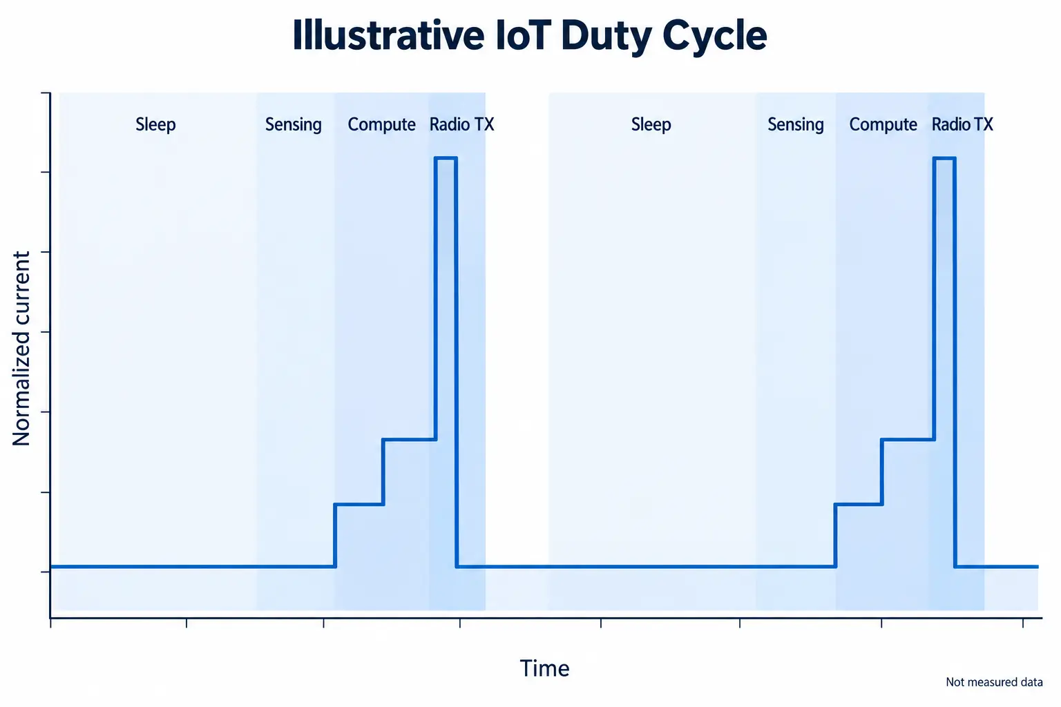
Create a time-based operating profile for one representative cycle. Measure at the battery terminals or a known point whose conversion losses can be accounted for. Chipset current figures are useful for early estimates, but the final profile must include regulators, sensors, LEDs, pull-ups, leakage, startup transients and firmware timing. [1] [3]
| Operating state | Record | Common omission |
|---|---|---|
| Deep sleep | Current and dwell time | Regulator and pull-up leakage |
| Sensor warm-up | Current, duration and repetition | Heater or analog settling time |
| Local processing | Current and duration | Flash write and clock transitions |
| Radio attach or scan | Current distribution and timeout | Poor-signal retries |
| Data transmission | Pulse current, width and count | Network-dependent tail time |
| Fault or update mode | Current and maximum duration | Firmware update and recovery behavior |
Use representative and adverse network conditions. Cellular and LPWAN devices may spend far longer attaching or retrying than a laboratory average suggests. For Bluetooth or Wi-Fi products, include scan, association and reconnection behavior rather than measuring only the payload burst. [1] [2]
3. Calculate Capacity and Usable Energy
For a discrete mission profile, the charge consumed in one cycle is:
FORMULA / Q_cycle = Σ(I_i × t_i) / 3600
where current is in milliamperes, time is in seconds and charge is in milliampere-hours. Average current follows from the same profile:
FORMULA / I_avg = Σ(I_i × t_i) / T_cycle
Charge-based arithmetic is convenient, but a constant-power load draws more current as battery voltage falls. If the regulator or load behaves approximately as a constant-power system, evaluate battery-terminal energy as well:
FORMULA / E_cycle = ∫ V_bat(t) × I_bat(t) dt
The required nominal capacity can then be screened as:
FORMULA / C_screen = Q_required / f_usable
Here, f_usable is the project-qualified usable fraction—not a universal 80% rule. If Q_required is derived from a measured battery-terminal waveform, regulator and conversion losses are already embedded in that measurement and should not be deducted again. In that case, f_usable should represent the accessible fraction of nominal capacity after device cutoff, pulse sag, temperature, expected aging, cell variation and the defined reserve requirement. If the starting data are measured on the load side instead, translate the load profile to battery-terminal charge or energy using measured or qualified conversion efficiency before applying f_usable. A pack can retain charge that the device cannot use because the voltage collapses below the system threshold during a pulse.
| Strong engineering input | Weak substitute |
|---|---|
| Measured battery-terminal waveform | Radio data-sheet peak alone |
| Complete operating-cycle timing | One “typical current” number |
| Minimum and maximum temperature | Room-temperature result only |
| Defined device cutoff and reset threshold | Nominal cell voltage only |
| Required runtime at an aging point | Beginning-of-life runtime only |
Capacity is therefore a result of the mission profile and usable-voltage window. Select the smallest capacity that satisfies the verified runtime and pulse requirements with the required production margin; do not choose capacity by enclosure volume alone. After fixing the electrical requirement, use the LiPo battery models page to screen candidate geometries by size and capacity.
4. Verify Peak Current and Voltage Sag
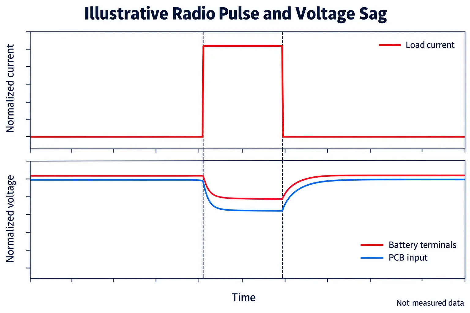
An IoT device can pass an average-current calculation and still reset during a short transmit burst. The voltage seen by the electronics depends on the cell, state of charge, temperature, protection circuit, tabs, connector, wire and PCB power path.
A first-order pulse estimate is:
FORMULA / ΔV_interconnect ≈ I_pulse × R_interconnect
This is a first-order screen for the resistive interconnect path; it is not a complete electrochemical model. Cell dynamic sag should be treated separately because it changes with pulse duration, state of charge, temperature, aging and transient response. Define the measurement boundary explicitly so the same wire, connector, PCM or PCB resistance is not subtracted twice. The system-level estimate is:
FORMULA / V_PCB,pulse ≈ V_OC − ΔV_cell,dynamic − ΔV_PCM/weld − ΔV_harness − ΔV_connector/PCB
FORMULA / V_PCB,pulse ≥ V_brownout + V_margin
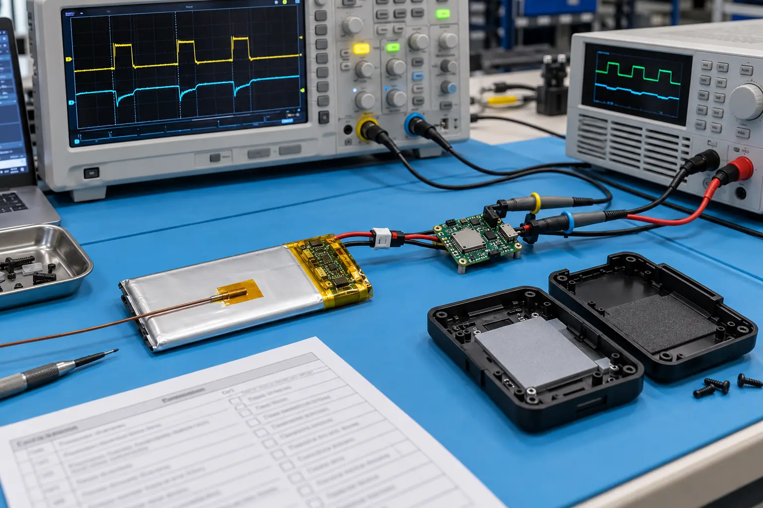
The release question is whether the predicted and measured PCB input voltage remains above the brownout threshold with the project-defined margin during the worst relevant pulse. Measure voltage and current simultaneously at the pack output and, when possible, at the PCB input. Use adequate oscilloscope bandwidth and time resolution for the pulse. Record the input-capacitor value, regulator mode and firmware state because a capacitor or converter may mask or reshape the battery pulse.
| Pulse test condition | Purpose |
|---|---|
| High and low state of charge | Reveals end-of-discharge reset risk |
| Room and minimum operating temperature | Captures cold resistance increase |
| New and aged cells | Checks life-dependent voltage sag |
| Strong and weak network conditions | Captures attach, retry and tail-current variation |
| Production-intent PCM and harness | Includes real resistance and trip behavior |
Do not infer pulse capability from capacity alone. Cell geometry, tab design and chemistry also matter. Use the LiPo battery C-rate guide for a broader explanation, then qualify the exact pack with the application waveform.
5. Match the Voltage Window and Charger
Treat the cell, charger, regulator and protection circuit as one electrical system. A nominal 3.7V label does not define the complete operating range.
| Item | Confirm |
|---|---|
| Maximum charge voltage | Cell chemistry and charger setting match |
| Device minimum input | Brownout and regulator dropout are known |
| PCM overcharge/overdischarge thresholds | Protection does not conflict with system behavior |
| Load during charging | Power-path and thermal behavior are acceptable |
| Recharge behavior | Deeply discharged or protected packs recover safely |
Do not substitute a 4.35V high-voltage cell for a conventional 4.2V cell without verifying the charger and system. Conversely, charging a high-voltage cell only to 4.2V changes available energy. See 4.2V vs 4.35V lithium battery charging for the design implications.
6. Design to Finished-Pack Dimensions
Model codes usually describe nominal cell dimensions, not the maximum assembled envelope. The finished pack can be longer, wider or locally thicker after adding the PCM, insulation, folded tabs, wires, connector, adhesive and tolerance stack.
| Mechanical input | What the battery drawing should show |
|---|---|
| Cavity dimensions and datum | Maximum finished length, width and thickness |
| PCB and enclosure keep-outs | PCM, tab and wire-exit zones |
| Assembly path | Insertion direction and allowable compression |
| Wire routing | Exit direction, bend radius and strain relief |
| Life-stage thickness / clearance | Clearance appropriate to qualified production variation, SOC, life and operating conditions |
Provide a 3D model or dimensioned cavity drawing when fit is critical. Avoid designing the enclosure exactly to a nominal pouch-cell number. Model-number conventions are useful for initial screening, while bare cell vs finished battery dimensions shows why assembly details change the final envelope.
7. Specify Protection, NTC and Ship Mode
Protection is part of the application design, not an accessory selected after the cell. Define the abnormal conditions, normal pulse current and charger behavior before choosing the PCM.
| Feature | Engineering question |
|---|---|
| Overcharge protection | Does the threshold suit the cell and charger? |
| Overdischarge protection | Will the trip point and release behavior suit the product? |
| Overcurrent/short-circuit protection | Can normal radio or motor pulses pass without nuisance trips? |
| NTC | What resistance, tolerance, beta value and temperature limits does the charger expect? |
| Ship mode | What current remains, and how is the pack awakened? |
For long-life IoT products, include PCM and monitoring-circuit quiescent current in the energy budget. A few microamperes matter when the device sleeps most of the time. Review the PCM/BMS selection guide and qualify the selected circuit with the final load.
8. Define the Connector and Harness
The connector specification must go beyond a series name. State the mating interface, pin count, pitch, polarity, wire gauge, wire length, wire exit direction and any latch or keying requirement.
| Harness variable | Risk if unspecified |
|---|---|
| Connector housing and terminal | Incorrect mating or contact rating |
| Polarity and pin numbering | Reverse connection and field failure |
| Wire gauge and length | Excessive pulse drop or routing conflict |
| Exit direction | Larger finished envelope or assembly interference |
| Strain relief | Fatigue at the tab or crimp |
For a mating sample, include clear photographs and the counterpart part number. The battery connector guide can help identify common families and mating details, but a production drawing should control the final configuration.
9. Account for Network, Temperature and Aging
Runtime and pulse performance are distributions, not single numbers. A useful qualification matrix includes the conditions that change current demand or internal resistance.
| Variable | Why it changes the result | Practical response |
|---|---|---|
| Weak network coverage | Longer attach, retry and transmit periods | Test realistic poor-signal scenarios |
| Low temperature | Higher cell resistance and lower usable energy | Test the minimum operating temperature |
| Aging and calendar time | Less capacity and greater voltage sag | Define an end-of-life acceptance point |
| Firmware update | Longer active time and repeated flash writes | Include update and recovery cycles |
| Component substitution | Different PCM or cell impedance | Require controlled change validation |
For a critical product, define acceptance limits for beginning of life and the intended aging point. Revalidate when the cell source, PCM, connector, wire, firmware power state, regulator or enclosure changes.
10. Worked Example: A 10-Minute IoT Reporting Cycle
Consider a sensor that wakes every 600 seconds. The example uses illustrative currents only; replace them with measurements from the actual board.
| State | Current | Duration | Charge per cycle | Notes |
|---|---|---|---|---|
| Deep sleep | 0.03mA | 591s | 17.73mA·s | Remaining cycle time |
| Sensor warm-up | 8mA | 3s | 24mA·s | Sensor dependent |
| Processing | 20mA | 2s | 40mA·s | Includes local compute |
| Radio transmission | 250mA | 4s | 1000mA·s | Network dependent |
| Total | — | 600s | 1081.73mA·s | Average current: 1.803mA |
For an idealized 1000mAh source, the charge-only calculation gives roughly 555 hours, or 23 days. If the radio state lasts only one second and sleep becomes 594 seconds, the cycle uses about 331.82mA·s, average current falls to about 0.553mA and the idealized result rises to roughly 75 days.
The comparison shows why radio timing and network behavior must be measured. Neither result is a production runtime promise: usable capacity, conversion efficiency, low-temperature behavior, self-discharge, aging and the device cutoff still have to be applied. The four-second case must also pass the pulse-voltage test near the end of discharge.
11. Diagnose Common Failures
| Symptom | Likely mechanisms | Next measurement |
|---|---|---|
| Reset during transmission | Voltage sag, harness drop, regulator response or PCM trip | Simultaneous pack and PCB voltage/current waveforms |
| Runtime is shorter than predicted | Incomplete duty cycle, poor network, leakage or early cutoff | Multi-cycle battery-terminal energy log |
| Pack does not fit | Nominal cell size used instead of finished dimensions | Production-intent pack and cavity measurement |
| Intermittent charging | Wrong NTC, connector contact or power-path interaction | Charger status, NTC and connector drop |
| Standby drain is excessive | PCM, regulator, gauge or wake leakage | State-by-state microamp current measurement |
| Prototype passes but production varies | Cell/PCM variation or uncontrolled substitution | Lot comparison against approved limits |
12. Validate Prototypes and Production
Prototype testing should reproduce the application rather than rely only on a bench discharge at constant current.
| Validation stage | Minimum evidence |
|---|---|
| Electrical prototype | Mission-profile current, pulse sag and cutoff behavior |
| Mechanical prototype | Finished dimensions, assembly path, routing and retention |
| Environmental check | Relevant temperature extremes and charging conditions |
| Aging check | Capacity and pulse margin at the defined life point |
| Production release | Approved drawing, BOM, limits and change-control triggers |
Use production-intent samples for the final validation. Confirm polarity, connector retention, protection operation, thermistor behavior and the exact finished envelope. The custom battery project process shows how requirements move through engineering review, production-intent samples and release control.
Product compliance depends on the market, equipment category, pack configuration and shipping route. IEC 62133-2 addresses safety requirements and tests for portable sealed secondary lithium cells and batteries. [4] UN Manual of Tests and Criteria subsection 38.3 governs transport testing for lithium cells and batteries. [5] Work with qualified compliance partners to determine the exact obligations for the final product; a component certificate does not automatically certify the host device.
13. Prepare an Engineering RFQ
An effective request lets the battery engineer evaluate the electrical, mechanical and production risks without repeated clarification.
| RFQ input | Preferred detail |
|---|---|
| Device and use case | Product function, environment and expected life |
| Runtime target | Hours/days between charges and life point |
| Mission profile | Current-versus-time data, including abnormal modes |
| Pulse requirement | Peak current, duration, repetition and minimum SOC |
| Voltage architecture | Charger, cutoff, brownout and regulator information |
| Mechanical envelope | Maximum finished dimensions, drawing and keep-outs |
| Pack configuration | PCM, NTC, connector, polarity, wire and labeling |
| Commercial plan | Prototype quantity, annual volume and schedule |
Use the RFQ inputs above to define the scope of custom battery engineering support. THOR Power can then assess cell geometry, protection, harness, finished dimensions and the validation plan as one pack specification.
Key Takeaways
- Base the battery choice on a measured, battery-terminal mission profile.
- Check energy and pulse voltage separately; average current does not prove radio-burst stability.
- Define the usable capacity fraction from the real cutoff, temperature, aging and load profile.
- Design the enclosure around the maximum finished pack, not the nominal pouch-cell code.
- Freeze the PCM, NTC, connector, wire and drawing before production qualification.
- Revalidate when firmware, radio behavior, pack components or mechanical constraints change.
Planning a Smart or IoT Device Battery?
Send the mission profile, pulse load, voltage window, finished battery space, connector, environmental limits and production quantity. THOR Power can review the electrical and mechanical pack requirements before samples are built.
14. Frequently Asked Questions
What is the best battery for a smart or IoT device?
There is no universal best capacity or cell format. The correct pack supports the measured mission cycle and worst pulse, fits the finished mechanical envelope, works with the charger and voltage thresholds, and can be produced consistently.
How do I calculate battery capacity for an IoT product?
Sum current multiplied by time for every operating state, convert the result to charge per cycle, multiply by the number of cycles in the required service interval, and divide by a project-qualified usable fraction. Also calculate energy if the load is closer to constant power.
Why does an IoT device reset during radio transmission?
The radio pulse may pull the PCB input below its brownout threshold because of cell impedance, low state of charge, cold temperature, PCM resistance, connector or wire drop, input capacitance or regulator dynamics. Capture voltage and current waveforms to locate the drop.
Does a higher mAh rating always increase runtime?
Not proportionally. Runtime also depends on the voltage window, pulse sag, conversion efficiency, temperature, self-discharge, aging and firmware behavior. A larger pack may help, but it must still meet fit and power requirements.
Can I replace a 4.2V LiPo cell with a 4.35V cell?
Only after verifying the charger, protection thresholds, system voltage limits and desired usable energy. The maximum charge voltage is a system-level requirement, not an interchangeable label.
How much peak current can a LiPo battery provide?
It depends on the specific cell, pulse duration, state of charge, temperature, age and resistance of the complete pack. Validate the actual production-intent assembly with the application waveform.
What limits standby life?
Deep-sleep current, regulator and pull-up leakage, PCM/gauge current, self-discharge, wake frequency, network retries and storage temperature can all dominate long standby periods.
What should I send a custom battery manufacturer?
Send the device use case, runtime target, measured mission profile, pulse requirement, voltage architecture, finished-space drawing, environmental range, connector/polarity details, prototype quantity and expected production volume.
Conclusion
A reliable IoT battery design connects four layers: mission-cycle energy, pulse-current stability, voltage compatibility and the finished mechanical pack. When these are measured and documented together, the battery specification becomes testable, the prototype is more likely to represent production, and enclosure or field failures can be found before tooling and certification commitments.
Public Technical References
- [1] Analog Devices, Greatly Improve Battery Power Efficiency for IoT Devices.
- [2] Nordic Semiconductor, nRF9160 current consumption scenarios and Online Power Profiler guidance.
- [3] Texas Instruments, TIDA-00484 energy-harvesting and battery-life reference design.
- [4] IEC, IEC 62133-2:2017 + AMD1:2021.
- [5] UNECE, Manual of Tests and Criteria, Revision 8 and Amendment 1, including lithium-battery transport provisions in subsection 38.3.
Author and Technical Review
| Role | Person | Scope |
|---|---|---|
| Author | Victor Xiong | OEM battery development, project definition and manufacturability |
| Technical reviewer | Dr. Maximilian Weber | Electrical boundaries, validation logic and production relevance |
Engineering boundary: Numerical examples in this article illustrate the method and are not guaranteed pack specifications. Final cell, PCM, connector, dimensions, operating limits and compliance route require project-specific engineering confirmation and production-intent validation.