LiPo Battery Standby Drain: Why Smart Devices Lose Charge While Off

Technically Reviewed By
Dr. Maximilian Weber
Chief Scientist
Dr. Maximilian Weber is THOR Power’s Chief Scientist and a senior expert in lithium battery technology. His technical review focuses on battery safety, performance optimization, energy density and custom battery solution development.
Last technical review: September 2026

Written By
Victor Xiong
President of OEM Division & Custom Battery Specialist
Victor Xiong holds a Master’s degree from The Chinese University of Hong Kong, Shenzhen. He leads THOR Power’s OEM Division and focuses on custom battery solutions for global device brands, product developers and industrial customers.
| Written By | Technically Reviewed By |
|---|---|
| Victor Xiong President of OEM Division and Custom Battery Specialist. Victor leads THOR Power custom battery development for smart devices, product developers and industrial OEM programs. | Dr. Maximilian Weber Chief Scientist. Dr. Weber reviewed this article for cell behavior, standby-current measurement, protection-circuit boundaries, storage-state assumptions and production validation logic. |
Quick Answer
A LiPo battery standby drain problem is usually a system current-budget problem, not simply a weak pouch cell. Separate LiPo self-discharge, battery quiescent current from the PCM, BMS or fuel-gauge circuit, and device sleep current. Then convert the measured current profile into storage-life loss, verify ship-mode wake behavior, and release the pack with defined post-storage reserve, open-circuit voltage and first-boot loaded-voltage requirements.
Four Approval Questions
Has the team measured cell-only, finished-pack and device-connected drain separately?
Does the off, sleep or ship-mode current include periodic wake bursts, wireless checks and indicator leakage?
Is the storage interval tied to a minimum post-storage open-circuit voltage, a first-boot loaded-voltage requirement and usable reserve, not only a nominal capacity label?
Can firmware, PCM/BMS settings, connector routing and production testing repeat the approved standby result?
Table of Contents
- Why power off is not always an electrical disconnect
- Separate cell self-discharge, pack quiescent current and device sleep current
- Convert microamps into a storage-life budget
- Measure standby current without disturbing the device
- Decide between sleep mode, ship mode and physical disconnect
- Why small custom LiPo batteries are more exposed
- Keep storage SOC and temperature separate from standby current
- Smart-device application priorities
- Put standby drain into the production specification
- What buyers should send in an RFQ
Key takeaways, conclusion, FAQ and technical references
1. Why Power Off Is Not Always an Electrical Disconnect
When a customer says the battery drains while off, the first question is not whether the cell is defective. In most smart devices, off usually means the screen and main processor are inactive. It does not always mean the battery is electrically isolated from the protection circuit, charger IC, real-time clock, wireless wake circuit, fuel gauge or leakage path on the device PCB.
That distinction matters because a healthy LiPo pouch battery can pass capacity testing and still arrive at the end user with too little voltage margin after warehouse storage. The product may fail first boot, reset during pairing, show a false low-battery warning or refuse charging because the protection threshold has already been crossed.
A good custom LiPo design therefore treats standby drain as a release requirement. Capacity, dimensions and connector choice are not enough. The battery specification must define the allowed drain path, storage duration, starting state of charge, temperature assumption, minimum post-storage voltage and the test method used to prove the result.
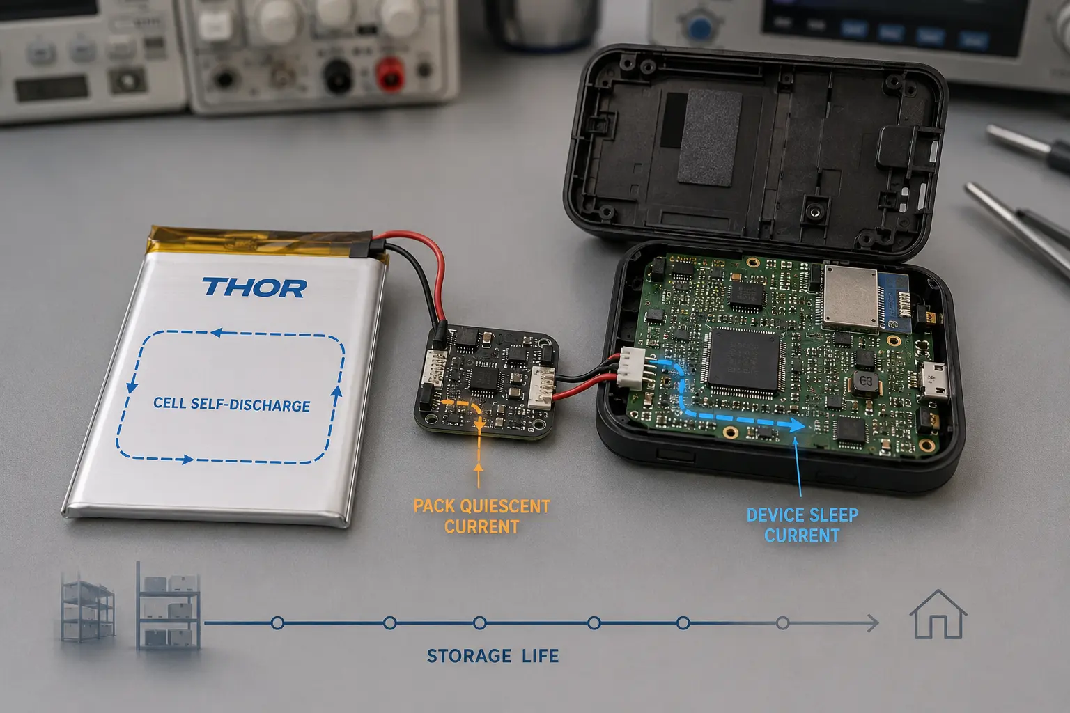
2. Separate Cell Self-Discharge, Pack Quiescent Current and Device Sleep Current
Standby loss has to be split into three different mechanisms. If they are measured together too early, the team may blame the cell, oversize the pack or change the PCM when the real issue is device firmware or a small always-on circuit.
| Drain path | How to isolate it | Engineering decision |
|---|---|---|
| Cell-only self-discharge | Store bare or sample cells at defined SOC, temperature and time, then compare open-circuit voltage and retained capacity. | Confirms whether the selected cell chemistry and supplier lot are suitable for the storage interval. |
| Pack quiescent current | Measure the finished pack with PCM, BMS, NTC, gauge or connector assembly installed, but disconnected from the device. | Shows whether protection, balancing, LEDs, pullups or gauge circuits consume too much current for shelf life. |
| Device sleep current | Measure the complete device in its real off, sleep or ship-mode state, including firmware and wake events. | Confirms whether the final product can survive distribution, storage and first-use conditions. |
Cell-only behavior is where LiPo self-discharge belongs. Pack-level standby is where battery quiescent current belongs. Device-level standby is where firmware, charger behavior and peripheral leakage belong. Keeping these buckets separate makes the corrective action much cleaner.
3. Convert Microamps Into a Storage-Life Budget
Microamp numbers look harmless until they are multiplied by time. A 100 uA always-on load consumes about 72 mAh in 30 days and about 216 mAh in 90 days. On a 5000 mAh pack that may be manageable; on a 300 mAh wearable cell it can remove a large share of the usable reserve before the customer opens the box.
Use a time-weighted average current when the device wakes periodically, then convert that average into storage loss:
Average standby current: Iavg = sum(Ii x ti) / T
Standby loss in mAh = Iavg (mA) x 24 x storage days
Qremaining = Qstart,usable – Qconnected – Qself-discharge
Release condition: Qremaining >= Qrequired + Qguard
Iavg should represent the complete repeating standby cycle, including baseline sleep current, scheduled wake events, wireless retries, status checks and other periodic bursts. Qremaining is the physical usable capacity left after storage; Qrequired is the energy needed for the defined first-use sequence, and Qguard is the project reserve for production spread, temperature, aging and measurement uncertainty.
| Average standby current | 30-day loss | 90-day loss | Illustrative impact |
|---|---|---|---|
| 10 uA | 7.2 mAh | 21.6 mAh | Low absolute loss, but still compare it with usable reserve and storage duration. |
| 50 uA | 36 mAh | 108 mAh | Can become material in sub-500 mAh packs or long storage intervals. |
| 100 uA | 72 mAh | 216 mAh | Requires explicit storage-life budgeting in small packs and standby-sensitive products. |
| 200 uA | 144 mAh | 432 mAh | Can dominate the available reserve in compact devices unless storage time is short or the pack is large. |
These current values are illustrative, not universal pass/fail thresholds. Their significance depends on usable battery capacity, storage duration, shipping SOC, temperature, first-boot load, minimum device voltage and the required project reserve. The budget should not assume that 100 percent of nameplate capacity is available. Production tolerance, aging, shipping SOC, low-temperature operation, cutoff voltage and minimum device voltage all reduce usable energy.
For products whose first boot includes a radio, motor, display or processor burst, storage-life reserve should be checked together with loaded-voltage margin. THOR Power's LiPo Battery Voltage Sag guide covers that separate peak-load failure mode.
4. Measure Standby Current Without Disturbing the Device
Many standby failures survive development because the measurement itself wakes the device or averages the wrong interval. A multimeter placed in series can introduce burden voltage, break the battery connection long enough to reset firmware, or miss periodic current bursts. A short reading also hides wireless check-ins, fuel-gauge updates and charger-status polling.
For a production-intent measurement, document the exact firmware version, battery SOC, device state, ambient temperature, sampling rate, measurement duration and wake-trigger condition. The test should capture both baseline sleep current and periodic bursts. If the device has multiple off states, record each state separately instead of reporting one generic standby number.
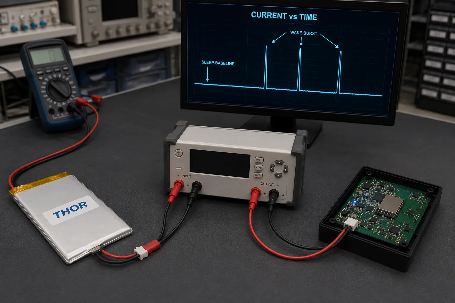
The most useful output is a time-current profile. It shows whether the product has a clean low-current baseline, whether wake bursts are expected, and whether the device returns to sleep after each event. This profile is much more useful than a single current value written on an RFQ form.
5. Decide Between Sleep Mode, Ship Mode and Physical Disconnect
Sleep mode, ship mode and physical disconnect solve different problems. Choosing the wrong one can reduce standby drain but create a wake-up, service or user-experience problem.
| State | Best use | Main validation risk |
|---|---|---|
| Sleep mode | Products that need fast wake, scheduled sensing or remote communication. | Average current can be higher than expected because firmware wakes periodically. |
| Ship mode | Products stored for weeks or months before first use. | Wake method must work after storage, low voltage and charger connection. |
| Physical disconnect | Devices that can tolerate a switch, pull tab or service action. | Mechanical access, user handling and waterproofing can become the limiting factors. |
A very low ship-mode current is valuable only if the product can wake reliably in the field. The validation plan should include wake after storage, charger insertion, button press, final enclosure assembly and low-temperature conditions if the device will be shipped or stored cold.
Engineering note: ship-mode current is IC- and architecture-specific. Some power-management devices are designed for extremely low battery-side current in ship mode, but the actual target must come from the selected IC datasheet and the complete device leakage path. Do not treat one vendor's ship-mode figure as a universal product requirement. [1]
6. Why Small Custom LiPo Batteries Are More Exposed
Standby drain hurts small packs first. A small custom LiPo battery may have only a few hundred milliamp-hours of usable capacity, while the device still needs protection, an NTC path, a connector and sometimes a fuel gauge. The absolute current may be small, but the percentage of capacity lost during storage can be large.
This is why thin wearables, trackers, sensors, handheld accessories and compact medical devices should not select a cell only by thickness and nominal capacity. The pack supplier needs to know the storage target, device sleep current, wake method and minimum operating voltage. If the pack is chosen before those values are known, the project can pass early samples and fail during pilot production or retail storage.
For teams comparing possible pouch formats, THOR Power keeps standard references for LiPo battery models and small-capacity LiPo batteries. These starting points are useful only after the electrical standby requirement is known.
7. Keep Storage SOC and Temperature Separate From Standby Current
Storage state of charge and temperature affect long-term cell behavior, but they are not the same as connected standby drain. A warm warehouse, high storage SOC or long storage time can accelerate capacity loss. A device leakage path consumes capacity even when the cell chemistry itself is behaving normally.
Do not merge these into one vague explanation such as battery aging. Instead, define storage SOC, storage temperature, storage duration and allowed connected-load drain as separate requirements. This gives purchasing, firmware, electrical engineering and battery manufacturing the same acceptance target.
8. Smart-Device Application Priorities
Different products tolerate standby drain differently. When evaluating a LiPo battery manufacturer for smart devices, buyers should expect questions about how the device sleeps, wakes, charges and ships before a cell size or protection circuit is recommended.
IoT sensors and trackers need long storage and low average current between reporting events. The validation should include wireless wake bursts and poor-signal retry behavior.
Wearables and compact consumer devices need very low standby current because small packs leave little reserve after storage, display checks and first pairing.
Portable medical and monitoring devices need predictable first-use readiness. For a custom pouch lithium battery used in a medical device, the supplier should confirm shelf-life reserve, labeling, charger behavior and production traceability.
Industrial handheld devices may have larger packs, but barcode engines, radios and standby accessories can create hidden loads if firmware states are not locked before production.
9. Put Standby Drain Into the Production Specification
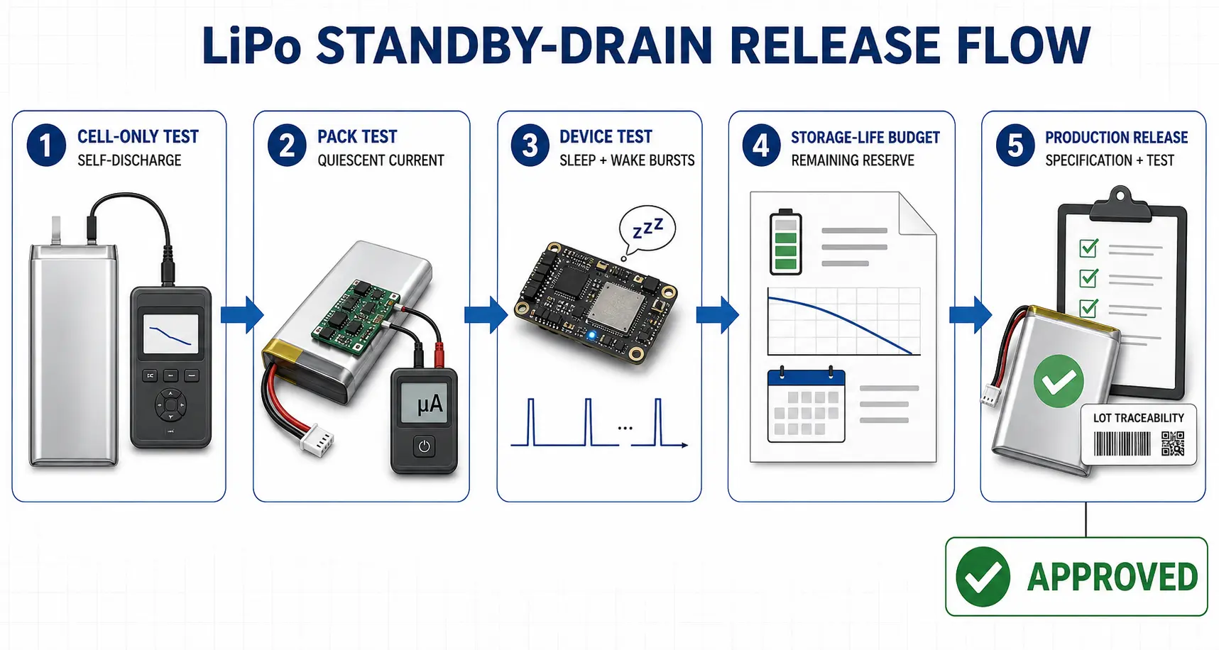
A standby-current target that stays in an engineer's test notebook is not enough. It must become part of the production-intent battery and device specification so future revisions do not quietly change the result.
A release-ready requirement should define:
Maximum average sleep current and the measurement window used to calculate it.
Maximum pack-only quiescent current with PCM, BMS, NTC, fuel gauge and connector assembly installed.
Required ship-mode entry method, exit method and acceptable wake time.
Starting SOC, storage temperature and storage duration, plus minimum post-storage open-circuit voltage and minimum first-boot loaded voltage under the defined startup profile.
Minimum remaining usable capacity after storage, expressed as Qremaining >= Qrequired + Qguard for the defined first-use sequence.
Firmware version, hardware revision and charger behavior used during validation.
Production test method, sample size and lot traceability for the approved configuration.
10. What Buyers Should Send in an RFQ
A stronger RFQ gives the battery supplier enough information to challenge the design before samples are built. For a standby-sensitive smart device, send more than voltage, capacity and size.
Target storage time before first use and expected shipping SOC.
Measured device sleep current, including whether the value includes periodic wake bursts.
Minimum device operating voltage and cutoff behavior under first-boot load.
Required protection functions, NTC value, connector type, wire length and polarity.
Charge method, charger IC behavior and whether the product needs ship mode.
Expected operating and storage temperature range.
Pilot-production validation plan, including sample quantity and pass/fail limits.
With those inputs, a supplier can decide whether the problem needs a larger pouch cell, a lower quiescent-current protection circuit, a firmware change, a true ship mode, a different connector arrangement or a tighter final-test rule.
Planning a Smart Device LiPo Battery Pack?
Send the storage target, device sleep-current profile, minimum operating voltage, connector requirement, charger behavior and enclosure constraints. A qualified LiPo battery manufacturer for smart devices should review the standby-current budget before recommending cell size, protection design or ship-mode strategy. THOR Power can define a production-intent battery-pack validation plan.
Talk to a Battery Engineer
Key Takeaways
LiPo battery standby drain is a system budget issue, not just a cell-capacity issue.
Separate cell self-discharge, pack quiescent current and device sleep current before choosing the corrective action.
Microamp loads become meaningful when multiplied by 30, 60 or 90 days of storage.
Ship mode helps only when wake behavior is validated after storage and low-voltage conditions.
Small custom LiPo batteries need stricter standby-current limits because they have less reserve capacity.
The approved standby result must be tied to firmware, hardware, battery configuration and production test limits.
Conclusion
If a smart device loses charge while it is off, the best response is not to guess at a larger battery. Build a standby-drain map, measure each loss path, convert the current into a storage-life budget, and validate the final battery-to-device configuration under production-intent conditions. That is how a LiPo pouch battery moves from a sample that works on a bench to a product that still wakes up after shipping, storage and first use.
FAQ: LiPo Battery Standby Drain
Why does my battery drain while off?
Most smart devices still have connected circuits when they appear off. Protection ICs, fuel gauges, chargers, real-time clocks, wireless wake circuits, LEDs or PCB leakage can consume current until the pack reaches a low-voltage limit.
Is LiPo self-discharge the same as battery quiescent current?
No. LiPo self-discharge is cell behavior during storage. Battery quiescent current is current consumed by electronics connected to the cell, such as a PCM, BMS, fuel gauge or charger circuit.
How much capacity does 50 uA use in one month?
A 50 uA load is 0.05 mA. Over 30 days it consumes about 36 mAh before accounting for cell self-discharge or the required project reserve.
Why does standby drain matter more for a small custom LiPo battery?
The same current removes a larger percentage of capacity from a small pack. A 36 mAh monthly loss is minor for a 5000 mAh pack but significant for a 200 mAh to 500 mAh wearable or sensor battery.
What is ship mode?
Ship mode is a low-current storage state designed to disconnect or greatly reduce the load before the product reaches the customer. It must include a reliable wake method such as charger insertion, button press or controlled host signal.
Should I solve standby drain by choosing a larger LiPo pouch battery?
Not first. A larger pack may add reserve, but it does not remove the root cause. Measure the drain path first, then decide whether the solution is lower quiescent-current electronics, firmware correction, ship mode, physical disconnect or more capacity.
What information should I send when sourcing a LiPo battery for a smart device?
Send the sleep-current profile, storage target, shipping SOC, minimum operating voltage, charge method, connector and wire requirements, NTC requirement, enclosure limits and validation target. These inputs let the supplier design the pack around real standby behavior.
Technical References
- Texas Instruments. BQ25120A battery charge management IC product page and datasheet. https://www.ti.com/product/BQ25120A
- Texas Instruments. BQ27441-G1 system-side Li-Ion/Li-Polymer fuel gauge product page and datasheet. https://www.ti.com/product/BQ27441-G1
- Analog Devices. Build a Charge Pump with Ultra-Low Quiescent Current (Iq). https://www.analog.com/en/resources/design-notes/build-a-charge-pump-with-ultralow-quiescent-current-iq.html
Reference scope: the TI and Analog Devices sources illustrate low-quiescent-current, fuel-gauge and ship-mode design principles. They do not define a universal standby-current target for every smart device.
Compliance Context
- International Electrotechnical Commission. IEC 62133-2:2017 lithium systems safety standard. https://webstore.iec.ch/en/publication/32662
- UNECE. UN Manual of Tests and Criteria, Revision 8 and Amendment 1, including subsection 38.3 lithium battery transport testing. https://unece.org/transport/dangerous-goods/rev8-files
- UL Solutions. Battery Safety Testing and Certification. https://www.ul.com/services/battery-safety-testing
Compliance scope: IEC 62133-2, UN 38.3 and UL battery-safety services relate to safety, transport or certification context. They do not define universal standby-current, self-discharge or storage-life limits and are not the basis of the equations in this article.
Related Engineering Guides
- What Size LiPo Battery Fits My Device?
- How to Choose a PCM or BMS for a Custom Battery Pack
- Custom LiPo Battery Size Guide
- Battery Pack Thermal Management Guide



Dr. Maximilian Weber is THOR Power's Chief Scientist and a senior expert in lithium battery technology. His technical review focuses on battery safety, performance optimization, energy density and custom battery solution development.
Last technical review: September 2026

Victor Xiong holds a Master's degree from The Chinese University of Hong Kong, Shenzhen. He leads THOR Power's OEM Division and focuses on custom battery solutions for global device brands, product developers and industrial customers.