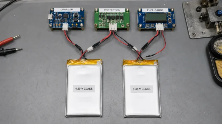
LiPo Battery Overcharge Protection: A 4.20 V Charger and a 4.25 V-Typical PCM


Technical reviewer: Dr. Maximilian Weber
Chief Scientist at THOR Power. Reviews battery safety boundaries, charger and protection IC coordination, worst-case analysis methodology, and evidence scope for design release.

Author: Victor Xiong
President, OEM Division & Custom Battery Specialist. Leads OEM battery programs for device brands, product developers and industrial customers.
ENGINEERING CASE NOTE | CASE-PCM-001 | PROJECT STATUS: ENGINEERING REVIEW
Why a 4.20 V charging target and a 4.25 V-typical, 4.20 V-minimum PCM threshold require a worst-case coordination review—not an automatic threshold increase.
Quick Answer for OEM Teams
A 4.20 V constant-voltage charger and a LiPo battery pack with a PCM overcharge detection threshold of 4.25 V typical and 4.20 V minimum do not automatically create repeated overcharge-protection trips. They also do not demonstrate a guaranteed separation between normal charging and the backup protection boundary.
The outcome depends on the charger’s guaranteed upper regulation limit, the voltage at the protection IC sensing point, the PCM’s actual detection threshold, how long an overvoltage condition persists, and the IC’s release and recovery behavior. Those values must be taken from the exact components and verified in the complete pack.
Raising the PCM threshold to approximately 4.28–4.30 V may create more nominal separation from a 4.20 V charger. It also allows a higher cell voltage before the backup protection responds during a qualifying fault. The correct sequence is therefore to confirm whether an unwanted trip occurs, identify the cause, and compare corrective options against the cell manufacturer’s charging limit and the applicable safety requirements.
Contents
- 1. Case Facts and Evidence Status
- 2. The Customer Question
- 3. What Was Known and What Was Not
- 4. Why Matching Nominal Values Do Not Predict a Protection Trip
- 5. The Margin Must Be Demonstrated as a Complete Stack
- 6. Why a Higher PCM Threshold Is Not an Automatic Fix
- 7. Three Engineering Options
- 8. What GB 31241-2022 Establishes
- 9. Recommended Validation Plan
- 10. Current Project Outcome
- 11. What OEM Teams Should Send for Review
- 12. Conclusion
- 13. Frequently Asked Questions
- 14. Technical References
1. Case Facts and Evidence Status
| Case field | Public record |
|---|---|
| Customer | Anonymized European OEM |
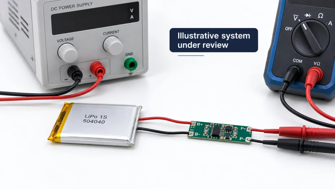
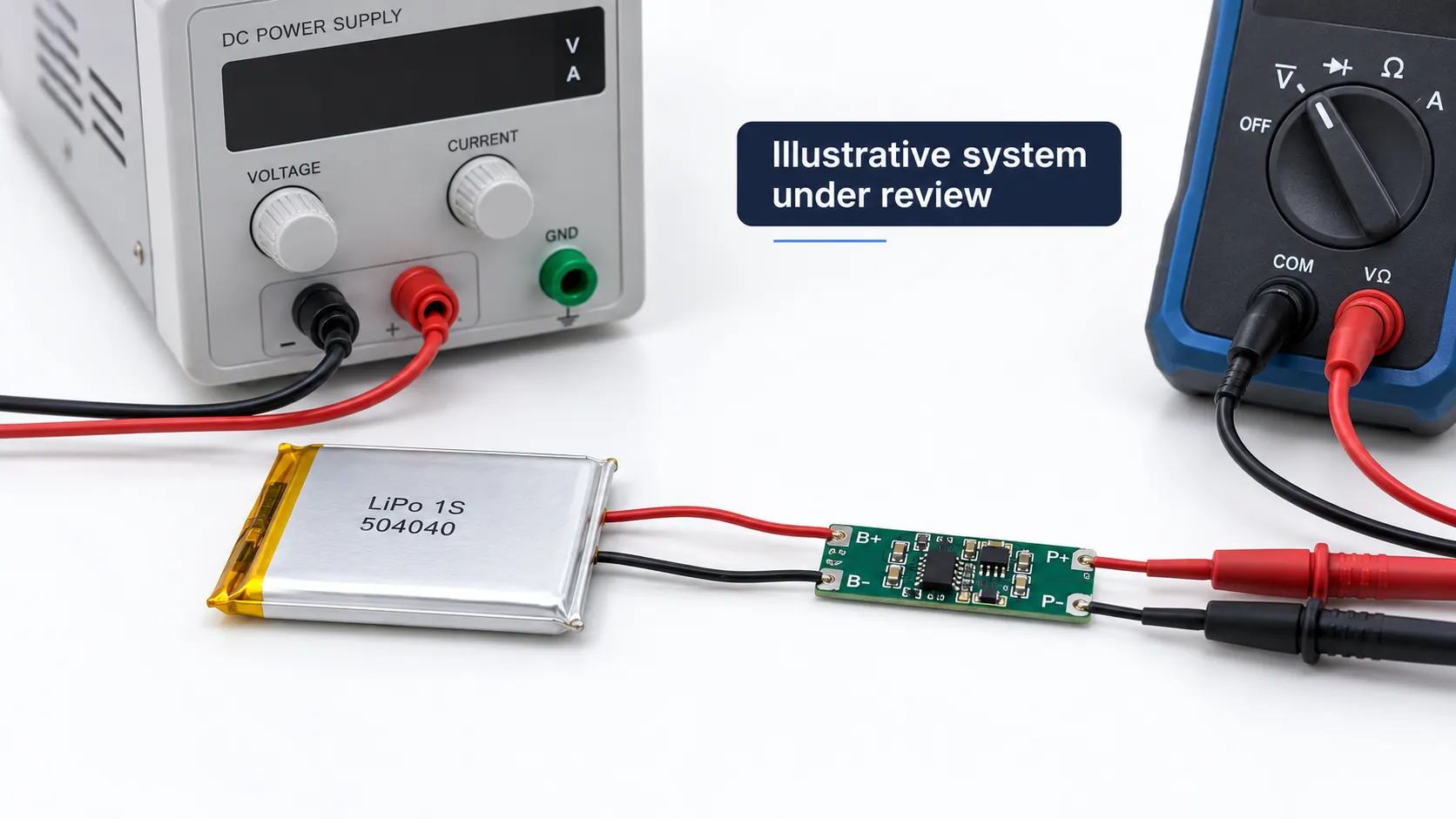
| Battery configuration | 1S 504040 lithium-ion polymer pouch-cell pack |
| Engineering question | Coordination of a 4.20 V charger with a PCM specified at 4.25 V typical and 4.20 V minimum overcharge detection |
| Project stage | Engineering review |
| Evidence status | Document-backed project question; no published measurement or final release record. |
| Outcome status | No verified nuisance trip, final PCM selection, or completed validation result is reported. |
2. The Customer Question
During a real battery-pack engineering review, a European OEM asked whether normal charging could trigger the pack’s overcharge protection. The 504040 pouch-cell pack was intended to use a 4.20 V charger. The PCM specification under review listed an overcharge detection voltage of 4.25 V typical and 4.20 V minimum.
The concern was understandable: if a production protection IC operated at the lower permitted boundary, could the end of a normal charge be interpreted as an overvoltage condition? One proposed response was to select a PCM with a typical detection threshold around 4.28–4.30 V and a minimum threshold of at least 4.25 V.
That proposal appears to create more voltage separation, but nominal numbers alone cannot show whether the original configuration would trip or whether the proposed threshold would provide an acceptable fault boundary. The review therefore had to separate known project inputs from information that was not yet available.
3. What Was Known and What Was Not
| Item | Known from the project question | Not confirmed in the public record |
|---|---|---|
| Cell format | 504040 pouch cell in a 1S LiPo pack | Exact cell manufacturer, revision, and approved upper charge limit |
| Charger | 4.20 V nominal target | Guaranteed accuracy, temperature behavior, ripple, transient response, and feedback point |
| PCM threshold | 4.25 V typical and 4.20 V minimum | Exact protection IC, maximum value, temperature drift, and production distribution |
| Protection timing | A delay is relevant to the decision | Exact detection delay, release delay, hysteresis, and recovery conditions |
| Observed behavior | A possible nuisance trip was questioned | No correlated cell-voltage and protection-output waveform was available |
| Final decision | A higher threshold was proposed | No released component or completed validation result is claimed |
4. Why Matching Nominal Values Do Not Predict a Protection Trip
A charger marked 4.20 V does not hold exactly 4.200 V under every input, temperature, load, and production condition. The engineering value needed here is not the nominal target but the guaranteed operating envelope from the exact charger specification. For a related explanation of cell voltage classes and charger compatibility, see the 4.20 V vs. 4.35 V lithium battery charger compatibility guide.
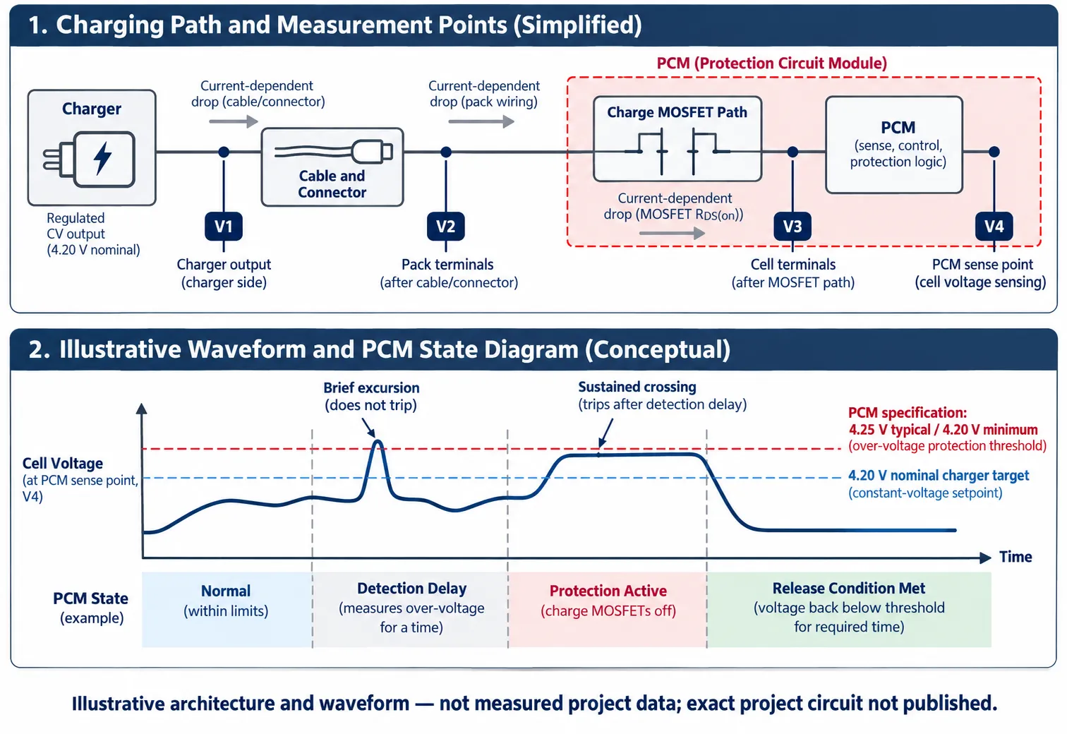
The voltage also depends on where it is measured. Charger output, pack terminals, cell terminals, and the voltage sensed by the protection IC can differ because of circuit topology, wiring, connector resistance, PCB traces, MOSFETs, and current-dependent voltage drop. As charge current tapers, some of those drops change. A conclusion based on the wrong measurement point may therefore describe a voltage that the protection IC never sees.
For a protection event to occur, the sensed voltage normally has to cross the actual detection threshold and remain there long enough to satisfy the selected IC’s detection logic. A short transient and a sustained overvoltage condition are not equivalent. The relevant delay is component-specific and must come from the controlled datasheet for the actual IC.
Recovery is equally important. Depending on the design, protection may release after the cell falls below a specified voltage, after the charger is removed, after a load is detected, or only after another defined condition. Without the exact release logic, it is not possible to predict whether a trip would be momentary, latched, or repeatedly cycled near the end of charge.
Need a Charger–PCM Coordination Review?
Send the charger specification, PCM datasheet, and any end-of-charge waveform. THOR Power can help identify the missing evidence before you change the protection threshold.
5. The Margin Must Be Demonstrated as a Complete Stack
The minimum PCM threshold and maximum charger output cannot be reviewed as two isolated numbers. A useful worst-case assessment includes every contributor that can move the operating point or the protection boundary.
| Stack item | Evidence needed | Why it matters |
|---|---|---|
| Cell charge limit | Controlled cell specification | Defines the permitted normal charging boundary |
| Charger upper limit | Guaranteed tolerance over input and temperature | Defines the highest normal regulation value |
| Ripple and transient | Waveform at relevant measurement points | Shows excursions that a static meter may miss |
| Sense-point difference | Circuit review and measured voltage drop | Confirms what the protection IC actually detects |
| PCM threshold | Exact min, typical, and max values | Defines the guaranteed protection range |
| Threshold drift | Temperature and operating-condition limits | Prevents room-temperature assumptions from becoming release criteria |
| Detection delay | Exact timing specification | Separates brief excursions from qualifying faults |
| Release behavior | Release voltage, delay, and charger/load conditions | Determines restart and repeated-transition behavior |
| Measurement uncertainty | Instrument accuracy and test method | Prevents a small calculated gap from being treated as proven margin |
If any of these values is missing, the correct conclusion is that the coordination margin has not yet been demonstrated. Substituting a convenient charger tolerance or a generic protection-IC delay may make the calculation look complete without making it specific to the product.
6. Why a Higher PCM Threshold Is Not an Automatic Fix
The charger should control normal charging within the cell manufacturer’s approved voltage range. The PCM provides backup protection when an abnormal condition crosses its qualified threshold for the required time. Moving that threshold higher does not increase the cell’s permitted normal charge voltage; it changes when backup protection is expected to intervene. For the broader component-selection framework, see the PCM/BMS selection guide.
A higher threshold may be appropriate in a coordinated design, but only after the cell limit, charger envelope, PCM tolerance, delay, recovery, and applicable fault tests have been reviewed together. Choosing 4.28–4.30 V merely because it sits farther from 4.20 V can exchange one unverified concern for a different unverified safety margin.
7. Three Engineering Options
| Option | When it may be appropriate | Evidence required before release |
|---|---|---|
| Validate the existing combination | No nuisance trip has been demonstrated and the components may already be coordinated | Exact documents, end-of-charge waveform, protection-output correlation, temperature coverage, and repeat testing |
| Improve normal-charge control | The charger exceeds its intended envelope or produces problematic ripple or transients | Revised charger configuration, confirmed sense point, updated tolerance stack, and complete-pack retest |
| Select a different protection IC | The existing threshold tolerance, delay, or recovery cannot meet the system requirement | Cell-maker limits, guaranteed IC values, fault analysis, production-intent samples, and applicable safety validation |
The preferred option is the one that produces stable normal charging while maintaining a justified backup-protection boundary. For a broader discussion of protection architecture, see the lithium-ion battery safety engineering guide. The part with the highest threshold is not automatically the best part, and the part with the lowest threshold is not automatically the safest.
8. What GB 31241-2022 Establishes
GB 31241-2022 is China’s current safety technical specification for lithium-ion cells and batteries used in portable electronic equipment. The official standard record shows that it took effect on January 1, 2024. Its overvoltage-charge protection requirements apply to defined test configurations and conditions.
The standard should not be reduced to a universal statement that every single-cell PCM must use one normal-operation trip threshold. A real compliance decision must use the controlled standard text, the applicable clause, the declared charging limits, and the complete battery or product configuration. In this case, 4.25 V typical and 4.20 V minimum are values from the PCM specification under review, not a universal threshold attributed to the standard.
9. Recommended Validation Plan
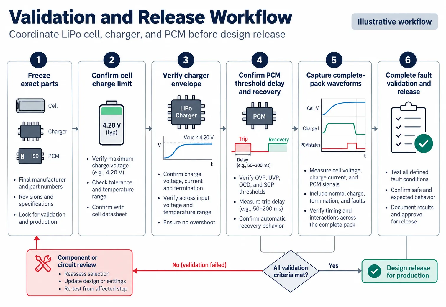
Freeze the exact cell, charger, PCM, connector, and circuit revisions. Record datasheet versions and the production-intent bill of materials. For a step-by-step view of how this process fits into a full custom battery development program, see the project workflow guide.
Define the measurement points before testing. At minimum, distinguish charger output, pack terminals, cell terminals, and the protection IC sense point where accessible and safe.
Measure the constant-voltage phase under the approved input-voltage and temperature range. Record voltage, current, ripple, and relevant transients instead of relying on a single steady meter reading.
Correlate cell voltage with the charge-control or protection output. This distinguishes a real PCM trip from charger regulation, contact resistance, measurement artifacts, or another circuit state.
Repeat the test across representative samples and lots. A single golden sample cannot demonstrate production margin.
Evaluate abnormal charging and recovery using a qualified safety procedure. Confirm the trip boundary, delay, release behavior, and post-fault state without improvising hazardous abuse tests on a normal bench.
Release only the complete configuration. Any change to the cell, charger, protection IC, sensing path, firmware, or assembly requires documented change control and appropriate revalidation. For the wider sample-to-release workflow, see the battery pack prototype testing and final-device validation guide.
10. Current Project Outcome
The available project record supports the need for a coordinated worst-case review. The design decision remains open until the charger envelope, relevant voltage waveforms, protection timing and recovery behavior, and the approved cell charge limit are documented.
The key lesson is that neither matching nominal values nor selecting a higher nominal threshold closes the design review. The missing evidence must be obtained before the protection boundary is changed.
11. What OEM Teams Should Send for Review
- Exact cell datasheet and revision
- Charger IC or module model, configuration, guaranteed voltage accuracy, ripple, and transient information
- PCM or protection IC model and complete datasheet
- Battery and charger schematic or a marked-up block diagram showing sensing points (see connector, wire and PCM/BMS customization for reference)
- End-of-charge voltage and current waveform, including the protection output if available
- Operating temperature, input-voltage range, charging states, and observed recovery behavior nnn
- Pack connector type and wire gauge (refer to the battery connector guide for standard options)
- Target market, product category, and applicable safety or certification requirements
12. Conclusion
A 4.20 V charger paired with a PCM specified at 4.25 V typical and 4.20 V minimum deserves a documented coordination review. The nominal values do not prove that protection will activate during each full charge, but they also do not prove that a safe and repeatable margin exists.
The best engineering response is to verify the exact charger envelope, the voltage seen by the protection IC, the threshold and timing of the selected PCM, the cell manufacturer’s charging limit, and the system’s fault and recovery behavior. Stable normal charging and effective backup protection must be demonstrated together.
Need a Charger–PCM Coordination Review?
Send the cell datasheet, charger tolerance, PCM specification, and any end-of-charge waveform. THOR Power can help identify the missing evidence before you change the protection threshold.
13. Frequently Asked Questions
Can a 4.20 V charger trigger a PCM with a 4.20 V minimum threshold?
It is possible under some conditions, but it is not automatic. The result depends on the actual sensed voltage, the threshold of the selected IC, detection delay, transients, and the recovery logic.
Should the PCM threshold be increased to 4.28 V or 4.30 V?
Not solely to eliminate a theoretical overlap. A higher threshold may reduce nuisance-trip risk, but it also moves the backup intervention point. The change must be justified against the exact cell, charger, protection architecture, and validation requirements.
Does GB 31241-2022 require every LiPo PCM to trip at 4.25 V ± 0.05 V?
That should not be assumed. The applicable standard clause, product configuration, charging limits, and complete battery behavior must be reviewed. The threshold for a selected PCM comes from its controlled component specification.
Why is detection delay important?
An overvoltage condition generally must persist long enough to meet the selected IC’s detection logic. The exact delay is component-specific; a generic value should not be used to release a design.
Will charging restart automatically after overcharge protection?
Not necessarily. Release can depend on voltage, timing, charger removal, load detection, or other IC-specific conditions. Use the exact datasheet and verify recovery in the complete pack.
14. Technical References
- GB 31241-2022 official Chinese National Standards record — China’s current safety technical specification for lithium-ion cells and batteries in portable electronic equipment; effective January 1, 2024. Does not by itself prescribe a single overcharge threshold for all PCM designs.
Related Engineering Guides
Project evidence note. The threshold values discussed above originate from the controlled PCM specification reviewed for the anonymized project. Manufacturer and customer-identifying details are not published. Final design approval must use the exact cell, charger, and protection-component documents.