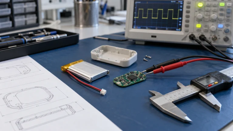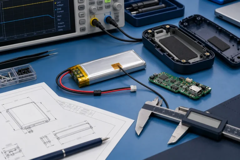
How to Maximize Usable Energy in a Small Custom LiPo Battery


Technical reviewer: Dr. Maximilian Weber
Chief Scientist at THOR Power. Reviews battery engineering content for technical accuracy, test boundaries and production relevance.

Author: Victor Xiong
OEM Division President at THOR Power, focused on custom lithium battery development and manufacturing for device programs.
A cavity-first guide to cell geometry, pack overhead, usable energy and production validation.
A compact battery is not simply a large battery scaled down. In a small device, fixed features such as the pouch seal, folded tabs, protection circuit module, insulation, wire exit and connector can consume a large share of the available envelope before the electrochemical body is considered. A 3 mm end stack occupies about 6.4% of a 47 mm cavity length but only 3% of a 100 mm cavity. That ratio is not a capacity prediction, but it shows why small packs must be designed as complete assemblies.
This guide explains how OEM teams can increase qualified usable energy inside a fixed device cavity without confusing nominal model size, finished battery size, catalog capacity and runtime under the real load. The objective is not the highest possible mAh at any cost. It is the highest capacity that can be manufactured consistently, installed safely and used by the device across its required temperature and life conditions.
Table of Contents
- Quick Answer
- Define the Finished Battery Envelope
- Recover Space From Pack Overhead
- Use Cell Geometry to Match the Cavity
- Size the Battery for Usable Energy and Pulse Stability
- Case Study: THOR 502030 for an Austrian Device Project
- Validate the Production-Intent Battery
- Prepare an Engineering RFQ
- Frequently Asked Questions
- Technical References
1. Quick Answer
Maximizing capacity in limited space begins with the finished battery envelope, not a requested catalog mAh value. The practical sequence is:
- Freeze the worst-case usable cavity on each axis, including local keep-out zones and the assembly path.
- Allocate space to the PCM, folded tabs, insulation, wire bend and connector before selecting the cell body.
- Use the flexible width or length axis to recover electrochemical volume when thickness is fixed.
- Calculate the energy the device can actually use and verify the worst pulse near the low end of charge.
- Approve production-intent samples and a revision-controlled finished battery drawing before releasing the enclosure.
There is no universal capacity per cubic centimetre, clearance allowance or swelling allowance that can be reused across projects. Chemistry, electrode design, charge voltage, current demand, packaging architecture, measurement conditions and life requirements all affect the result.
2. Define the Finished Battery Envelope
Start with the minimum usable cavity rather than the nominal CAD volume. Enclosure tolerances, PCB parts, ribs, screw bosses, adhesives, foam and installation access can all reduce the space that the battery may occupy. Record the maximum permitted finished battery thickness, width and length separately. A candidate with a smaller total volume can still fail if one hard axis or one local feature exceeds its limit.
| Mechanical term | Meaning | Use in the project |
|---|---|---|
| Nominal cell code | Approximate pouch body size used for model identification | Candidate discovery only |
| Maximum bare cell envelope | Released cell body limit under defined conditions | Cell-level review |
| Main finished-pack body envelope | Cell plus PCM, tab folds, insulation, tape and label within the primary body boundary | Primary rectangular cavity screen |
| Harness / connector local envelope | Wire exit, bend corridor, housing, local protrusions and mating access | Model as a separate controlled local volume |
| Complete installed battery envelope | Main pack body plus all controlled local protrusions and required service clearances | Final enclosure and assembly approval |
| Assembly margin | Remaining space after worst-case battery and device stack-up | Set by the project and assembly method |
The finished drawing should show both the main pack-body envelope and controlled local high points. A PCM may overlap the pouch body in length but create a thicker region over the tabs. A wire may be excluded from the main rectangular body while still requiring a controlled bend corridor. Final enclosure approval must consider the complete installed battery envelope, not one generic allowance added to all three axes.
For the detailed measurement and tolerance method, use the LiPo Battery Dimensions Guide and the Finished Battery Size guide. This article focuses on how to recover qualified capacity after the mechanical boundary is defined. If no standard geometry can meet that boundary without compromising power, life or manufacturability, move to a custom LiPo battery engineering review rather than forcing the enclosure around a catalog cell.
3. Recover Space From Pack Overhead
In a small pack, capacity may be limited by the arrangement around the cell rather than by the pouch chemistry. Protection electronics, insulation and the connector do not necessarily shrink in proportion to capacity. Their placement should be decided early enough that the cell can use the remaining space efficiently.
| Pack feature | How it consumes space | Engineering response |
|---|---|---|
| End-mounted PCM | Extends length and may create a local thickness step | Use when width is hard and end length is available |
| Side-mounted PCM | Consumes width and changes the contact area | Use only when side width and pressure conditions permit |
| Folded tabs and welds | Create concentrated length and thickness | Define fold direction, insulation and weld zone on the drawing |
| Wire exit | Requires routing volume and a bend corridor | Freeze exit side, gauge, length and permitted bend direction |
| Connector | Consumes a local pocket and mating access | Choose the exact housing and mating part before release |
| Tape, label and foam | Add thickness at overlaps and local zones | Measure the final assembly rather than the bare pouch |
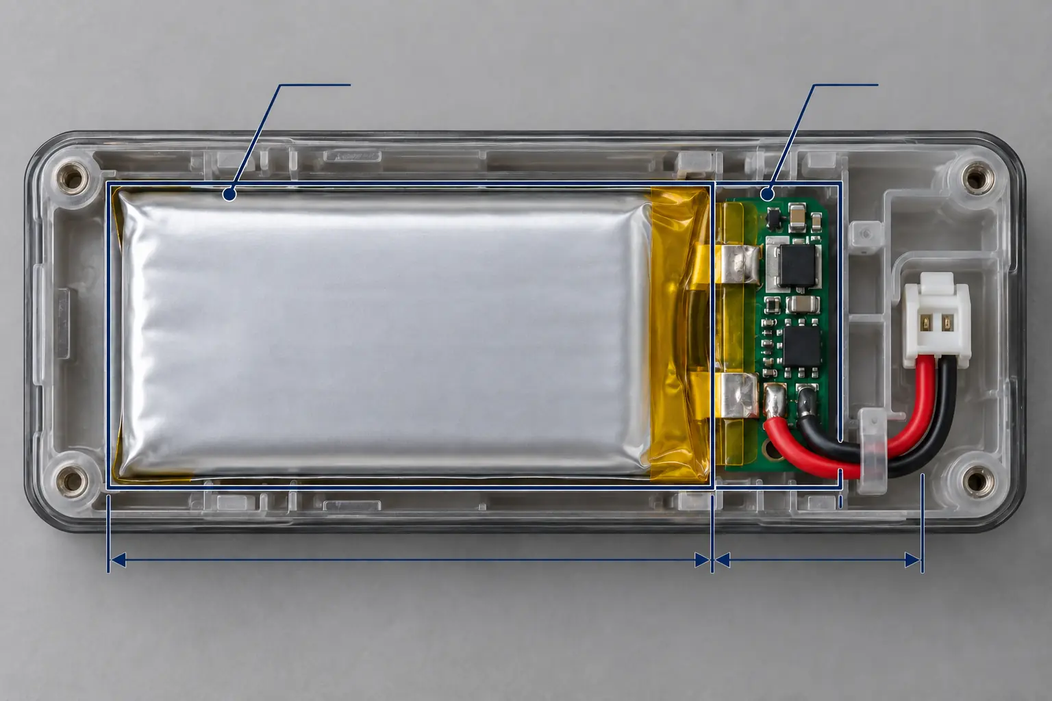
Engineering priority: Before requesting a more aggressive cell design, check whether changing the PCM location, tab fold, connector or wire route returns useful volume to the cell body. Packaging optimization may create capacity opportunity without increasing the device envelope.
When the device connector is not fixed, use the current Battery Connector Types Guide to define the mating series, pitch, pinout, wire gauge and polarity before the pack geometry is frozen.
4. Use Cell Geometry to Match the Cavity
The same nominal capacity can be built in very different thickness, width and length combinations. Those shapes are not automatically electrochemically equivalent, but they demonstrate why the correct pouch family should be selected from the cavity inward. A thin product may accept a wide cell. A pen-shaped device may need a narrow but thicker cell. Trying to minimize all three axes at once can force unnecessary compromises in power, life or manufacturability.
Two listed THOR Power 500mAh models illustrate the geometry choice. Both have a nominal energy of approximately 1.85Wh, but they target different enclosure shapes. The dimensions below are catalog screening values. The project drawing remains the approval document.
| Model | Bare cell size | Illustrative cell + PCM screening envelope | Geometry use |
|---|---|---|---|
| THOR 303450 | 3 × 34 × 50 mm | 3 × 34 × 52 mm | Very thin and wide cavity |
| THOR 701555 | 7 × 15 × 55 mm | 7 × 15 × 57 mm | Narrow, elongated cavity |
Screening note: The cell + PCM envelope above does not include project-specific wire, connector, local high points or service clearances unless explicitly stated. Final fit is controlled by the released finished-pack drawing.
A hypothetical cavity measuring 3.3 × 35 × 54 mm can screen the 303450 geometry but cannot accept a 7 mm-thick 701555. A narrow cavity measuring 7.3 × 16 × 59 mm reverses the result because the 303450 is too wide. This is an axis-by-axis screening exercise only; tolerance, local PCM height, wires, connector and service margin still require review.
Model references: THOR 303450 and THOR 701555. Browse the small capacity LiPo catalog to compare other aspect ratios.
5. Size the Battery for Usable Energy and Pulse Stability
A higher mAh value does not guarantee more useful runtime. The device can use only the energy delivered above its cutoff voltage and within the permitted temperature and current limits. At low state of charge or low temperature, voltage sag during a radio transmission, motor start or sensor pulse can trigger the device cutoff before the rated capacity is exhausted. Aging can increase resistance and reduce both available capacity and pulse margin.
Mission energy: Measure battery-terminal voltage and current over the complete operating cycle and calculate the energy used by the real duty profile. If the measurement is made at the battery terminals, conversion losses are already included and should not be deducted a second time.
Nominal energy target: Set the rated energy high enough to cover mission energy after applying a qualified usable-energy fraction and the project design margin. The usable fraction must reflect the actual cutoff voltage, load, temperature and defined life point rather than a universal percentage.
Higher energy loading can also trade against rate capability. Research comparing high-power and high-energy lithium-ion cell designs shows that the two objectives can require different electrode and component choices. Thick-electrode studies likewise show that added loading can increase energy potential while increasing ion-transport limitations and under-utilization at higher rates. These mechanisms explain why a higher-capacity candidate must still pass the application load; they are not performance specifications for a THOR model. [2] [3] [4] [5]
Evaluate continuous current, peak current, pulse duration, lowest state of charge, temperature, PCM threshold, wire and connector resistance, heat and device cutoff together. A compact pack that passes nominal capacity but fails the worst pulse is not an improvement.
Charge voltage is a separate system decision. Review 4.2V and 4.35V Lithium Battery Charger Compatibility before considering a higher-voltage platform. The cell, charger, protection thresholds, regulator and fuel gauge must all support the selected maximum voltage.
6. Case Study: THOR 502030 for an Austrian Device Project
An Austrian customer needed more runtime but could not enlarge the battery cavity. The available cell body was in the 502030 size class, approximately 5 × 20 × 30 mm. The original project baseline was 220mAh. Enlarging the pouch was not practical, so the engineering work focused on using the existing space more effectively.
THOR Power refined the electrode formulation and loading balance together with the sealing and packaging process to use the fixed envelope more efficiently. The reported project-specific configuration reached 290mAh within the customer’s fixed envelope. Within the project comparison, the change from 220mAh to 290mAh represents a 31.8% capacity increase. The project-specific capacity-test method and release conditions remain controlled engineering records, so this figure should not be treated as a standardized cross-cell benchmark. The optimized configuration was developed to address the agreed project energy target within the fixed space.
| Project item | Baseline | Optimized project result |
|---|---|---|
| Cell size class | 502030 envelope | 502030 envelope |
| Capacity | 220mAh | 290mAh |
| Relative increase | Reference | 31.8% |
| Engineering work | Existing project configuration | Electrode formulation, loading balance, sealing and packaging process refined within the fixed envelope |
| Customer benefit | Insufficient energy margin | Project energy target addressed within the fixed space |
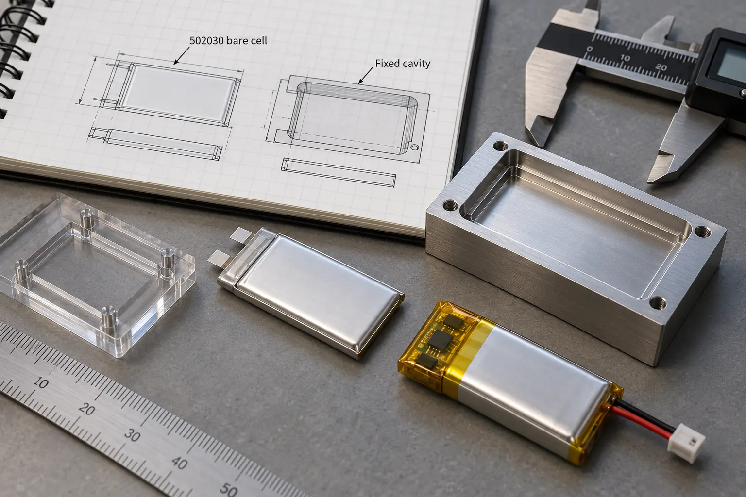
This result is a project-specific first-party engineering case. It does not mean that every 502030 cell can be changed to 290mAh or that capacity can be increased by 31.8% without trade-offs. Electrode loading, chemistry, process window, charge voltage, discharge requirement, cycle life and dimensional tolerance must be validated together. The current catalog THOR 502030 is a separate standard 250mAh reference configuration; the Austrian project used a custom configuration and its released specification remains project-controlled.
See the standard THOR 502030 3.7V 250mAh product detail page for the current catalog reference configuration. Custom project values should always be identified separately from the catalog specification.
7. Validate the Production-Intent Battery
One hand-selected sample can demonstrate feasibility, but it cannot establish a production distribution. Final approval should use the intended cell construction, PCM, wire, connector, insulation, label and assembly process. Record the drawing and bill-of-materials revision so later changes trigger the correct review.
| Validation stage | Minimum evidence before release |
|---|---|
| Mechanical | Maximum finished dimensions, local high points, wire route, connector pocket, assembly path and fit in representative enclosures |
| Capacity and energy | Capacity test conditions, usable energy above device cutoff and results at the defined temperature and life point |
| Load performance | Continuous and peak current, voltage sag, PCM behavior, connector drop and temperature rise at relevant state of charge |
| Charging | Exact maximum cell voltage, charger accuracy, charge current, protection thresholds, NTC behavior and gauge settings |
| Life | Capacity, resistance, pulse margin and dimensions at the agreed cycle or storage point |
| Production | Controlled drawing, BOM, measurement method, acceptance limits, traceability and change triggers |
Thickness deserves particular attention because a pouch cell is not a rigid machined block. State of charge, temperature, rest time, measurement method, production variation and life stage can change the measured result. Define the maximum production-intent thickness under agreed conditions instead of applying one universal swelling allowance. Keep normal life-stage dimensional allowance separate from abnormal swelling or abuse behavior.
Use Battery Pack Prototype Testing and Validation to plan drawing review, sample inspection, electrical testing and production release.
8. Prepare an Engineering RFQ
A useful RFQ gives the supplier enough information to optimize the complete pack rather than guess at a catalog replacement. Send:
- Minimum usable cavity or maximum finished battery thickness, width and length, including local keep-out zones
- Hard and flexible axes, assembly direction and permitted wire exit
- Required runtime, device cutoff and measured operating cycle
- Continuous current, peak current, pulse width, repetition and lowest state of charge of interest
- Charge voltage, charge current, regulator range and fuel-gauge requirements
- PCM, NTC, connector mating part, wire gauge, length, polarity and label requirements
- Operating, charging and storage temperatures plus the defined life target
- Prototype quantity, annual forecast, target markets and documentation requirements
Ready for an engineering review? Send the cavity and load requirements to THOR Power. The engineering team can screen standard geometries and determine whether layout optimization or a validated custom LiPo battery is justified. Use the custom battery inquiry form to submit the project requirements.
Planning a Small Custom LiPo Battery for a Fixed Cavity?
Send the usable cavity, load profile, cutoff voltage, pulse current, connector, PCM and life requirements. THOR Power can screen standard geometries and determine whether layout optimization or a validated custom configuration is justified.
9. Frequently Asked Questions
Can LiPo capacity be estimated from dimensions alone?
No. External thickness, width and length are useful for screening, but capacity also depends on chemistry, electrode loading, collectors, separator, seals, voltage class and design margins. Compare released cell specifications rather than applying one mAh-per-cubic-centimetre rule.
Does a smaller pack with the same mAh have higher measured energy density?
Not automatically. A smaller rectangular envelope may produce a higher nominal energy-per-envelope screening value, but measured cell or pack Wh per litre requires consistent energy tests and a clearly defined volume boundary.
Does the highest mAh candidate give the longest runtime?
Only if the device can use the added charge. Cutoff voltage, pulse sag, temperature, conversion efficiency and aging can make part of the nominal capacity inaccessible.
Can the PCM be moved to create more cell space?
Sometimes. End, side or back placement can change which axis is consumed, but electrical resistance, insulation, pressure, wire routing and manufacturability must be rechecked.
Can every 502030 battery be increased to 290mAh?
No. The Austrian result came from a project-specific custom configuration and controlled project comparison. It must not be treated as a universal catalog specification or applied without validating chemistry, power, charging, life, dimensions, production consistency and the project-specific capacity-test method.
What should be approved before production?
Approve the finished battery drawing, bill of materials, capacity and load-test conditions, charger compatibility, environmental and life criteria, measurement method, acceptance limits and change-control requirements.
10. Technical References
- [1] International Electrotechnical Commission. IEC 61960-3:2017. Secondary lithium cells and batteries for portable applications. Annex A covers dimensions of cells with a laminate film case. IEC official publication.
- [2] Lain, M. J.; Brandon, J.; and Kendrick, E. “Design Strategies for High Power vs. High Energy Lithium Ion Cells.” Batteries, 2019, 5(4), 64. DOI: 10.3390/batteries5040064.
- [3] Xie, W.; Zhang, Z.; and Gao, X. “Understanding the limitations of thick electrodes on the rate capability of high energy density lithium ion batteries.” Electrochimica Acta, 2024, 493, 144396. DOI: 10.1016/j.electacta.2024.144396.
- [4] Imediegwu, C.; Shaffer, M. S. P.; Ryan, M. P.; and Panesar, A. “Modelling optimum thickness and architecture for lithium ion battery cathodes.” Journal of Power Sources, 2024, 614, 235005. DOI: 10.1016/j.jpowsour.2024.235005.
- [5] Li, D.; Lv, Q.; Zhang, C.; Zhou, W.; Guo, H.; Jiang, S.; and Li, Z. “The Effect of Electrode Thickness on the High Current Discharge and Long-Term Cycle Performance of a Lithium Ion Battery.” Batteries, 2022, 8(8), 101. DOI: 10.3390/batteries8080101.
Evidence boundary: The cited publications explain general battery design and measurement principles. They are not THOR Power product specifications. Final capacity, dimensions, current, charge voltage, life and compliance requirements must be confirmed for the exact project configuration.