
Lithium-Ion Battery Safety Engineering Guide: Charging, BMS Protection, Thermal Runaway and OEM Risk Control

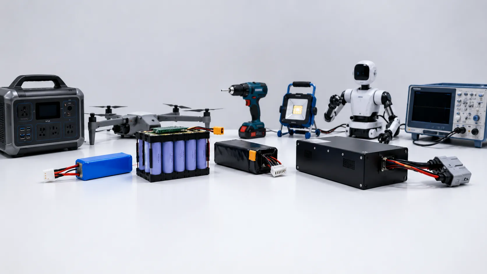
Lithium-ion batteries power compact electronics, medical and monitoring devices, power tools, robotics, industrial equipment, backup systems and many products that need rechargeable energy in a compact package. Their value is real: high energy density, flexible formats and chemistries that can be optimized for runtime, power, cycle life or thermal stability.
That same versatility creates a common safety mistake: treating lithium-ion as if it described one standardized battery. It does not. Lithium-ion is a family of rechargeable electrochemical systems. A pouch cell, cylindrical cell or prismatic cell may use different cathode materials, separators, electrolytes, current collectors, internal safety devices and operating limits. Two packs with the same nominal voltage and capacity can behave very differently under high current, fast charging, cold temperatures, mechanical stress or abnormal conditions.
For OEM and ODM projects, lithium-ion battery safety depends on the complete energy system rather than a single cell, BMS or certificate. A reliable design must connect cell chemistry and format with the real load profile, charging method, series-parallel configuration, protection thresholds, temperature sensing, interconnections, enclosure, heat path, manufacturing control, end-product behavior and documentation scope.
This guide is the system-level hub for THOR Power’s battery safety series. It explains the major causes of lithium-ion battery failure and thermal runaway, including overcharge, short circuit, internal defects, low-temperature charging, lithium plating, cell imbalance, poor thermal design, mechanical damage, aging and incompatible chargers or firmware. It also explains what a BMS can and cannot do, how safety priorities change by chemistry and cell format, and what OEM buyers should verify before approving a custom lithium-ion battery pack.
Product teams evaluating a pack can begin with THOR Power’s custom lithium-ion battery pack solutions, then confirm the final chemistry, cell model, protection architecture and production controls against the actual device requirements.
Quick Answer for OEM Buyers
Lithium-ion batteries can be used safely when the exact cell chemistry and model are operated within validated voltage, current, temperature and mechanical limits inside a properly engineered system. Safety depends on coordinated charging control, BMS logic, fusing, sensors, interconnections, thermal management, enclosure design, device firmware, manufacturing traceability and change control. No single component can compensate for a mismatched or poorly integrated battery architecture.
For product developers and purchasing teams, the highest risk is often hidden in an apparently successful prototype. A pack may reach the target voltage and runtime while the selected cell cannot support pulse current, the charging profile sits outside the cell approval sheet, the BMS sensor misses the hottest location, the enclosure traps heat, or the certification report does not cover the production configuration. These gaps create late redesign, failed compliance review, unstable mass production and avoidable field-quality risk.
1. What Is a Lithium-Ion Battery?
A lithium-ion battery stores and releases energy by moving lithium ions between a positive electrode and a negative electrode through an electrolyte while electrons travel through the external circuit. Most commercial rechargeable lithium-ion cells use a graphite-based negative electrode, but the positive-electrode chemistry, electrolyte formulation, separator and cell construction vary by model.
The name “lithium-ion” does not identify the physical shape of the cell. Lithium-ion cells may be manufactured as flexible aluminum-laminate pouches, cylindrical metal cans or prismatic housings. The name also does not define one nominal voltage, one charging limit or one current rating. Those values must come from the exact cell approval sheet.
In practical battery-pack engineering, the chemistry influences voltage, energy density, thermal response and life characteristics, while the form factor influences mechanical support, venting, interconnection and heat transfer. The final product must be designed around both.
2. Lithium-Ion Is a Battery Family, Not a Single Chemistry
Commercial lithium-ion products may use lithium cobalt oxide, nickel-manganese-cobalt systems, nickel-cobalt-aluminum systems, lithium iron phosphate or manufacturer-specific blends. Each option has a different balance of energy, power, cycle life, nominal voltage, cost and thermal behavior. General chemistry comparisons can guide the first discussion, but safety limits must always be confirmed at cell-model level.
| Chemistry Direction | Typical Application Direction | Safety Interpretation |
|---|---|---|
| LCO and related high-energy systems | Compact consumer electronics and small portable products | High energy in a small volume can be useful, but charge voltage, heat and mechanical protection require close control. Exact cell data must govern the design. |
| NMC / NCA and related blends | Portable equipment, tools, robotics and other energy-or-power applications | Available in models optimized for energy or current. Selecting by capacity alone can create excessive voltage sag and heat. |
| LiFePO4 / LFP | Industrial, backup-power and energy-storage applications, plus selected portable products | Often offers higher thermal stability and long cycle life, but it still requires correct charging, BMS protection, enclosure design and abnormal-condition validation. |
| Manufacturer-specific or emerging variants | Application-dependent | Nominal chemistry names do not replace the approval sheet. Charge limits, temperature range, current capability and safety evidence remain model-specific. |
This article acts as the broad lithium-ion safety hub. For pouch-cell details, use LiPo Battery Safety as the deeper spoke. For cylindrical-cell sourcing, wrap, venting, welding and propagation risks, use 18650 Battery Safety. This separation keeps the articles from competing for the same search result while giving buyers a clear path from broad safety questions to format-specific engineering details.
3. Are Lithium-Ion Batteries Safe?
Yes, lithium-ion cells and battery packs can be used safely when the exact cell chemistry and model are selected for the application, operated inside approved voltage, current, temperature and mechanical limits, and integrated with suitable charging, protection, thermal, mechanical and manufacturing controls. The technology is widely used because it can deliver reliable rechargeable power when the complete system is engineered correctly.
However, lithium-ion cells contain stored electrochemical energy and typically use combustible organic electrolyte. Severe overcharge, internal or external short circuit, excessive current, high temperature, mechanical damage, manufacturing defects or incompatible charging can generate heat faster than the cell can dissipate it. NREL summarizes potential cell-level heat sources as external short circuit, overcharge, external heating, penetration, crush, internal short circuit and other out-of-spec operation; at pack level, propagation, BMS malfunction and poor design add further hazards.
The correct question is therefore not whether “lithium-ion” is safe as a category. The correct question is whether the complete battery system keeps every cell inside a validated operating window, detects foreseeable abnormal conditions early enough, interrupts external energy where possible and limits the consequence if a cell develops an internal fault.
4. How to Define a Safe Lithium-Ion Battery Pack Specification
A safe lithium-ion battery project should begin with the operating conditions of the final device, not with a generic request for voltage and capacity. The specification must connect the energy requirement with current demand, charging behavior, thermal conditions, mechanical constraints and certification route before a production sample is approved.
The following table can be used as a project-start checklist. Unknown information does not always prevent prototyping, but it increases the probability that the first quotation or sample is based on assumptions that later require redesign. If the product requires a non-standard shape, connector, wire length, communication function or protection layout, use an early custom battery engineering review before the enclosure, charger and tooling are locked.
| Specification Item | What to Define | Why It Matters for Safety |
|---|---|---|
| Chemistry and cell model | Approved manufacturer, model, chemistry, form factor, charge profile, current rating and temperature limits | Lithium-ion is a family. Safety and performance depend on the exact cell, not the chemistry name alone. |
| Voltage and series count | Nominal voltage, maximum charge voltage, discharge cutoff and number of series groups | Series count determines total voltage, sensing architecture, balancing and insulation requirements. |
| Capacity and parallel count | Runtime target, usable capacity window and number of cells in parallel | Parallel design changes current sharing, available fault current and the energy involved if one cell fails. |
| Current profile | Standby, average, continuous, peak and regenerative current; pulse duration and duty cycle | Average current can hide motor start, radio transmission, inrush, stall or charging-backflow conditions. |
| Charging method | Input source, charge current, termination logic, temperature policy and power-path behavior | The charger must match the selected cell and device operating mode; a BMS is not a normal charge controller. |
| Protection architecture | BMS/PCM thresholds, MOSFET rating, balance function, fuse strategy, contactor logic and NTC inputs | Protection must match the configuration and real fault energy, not only the nominal pack voltage. |
| Mechanical and thermal design | Cell support, compression, insulation, vent path, heat sources, cooling and enclosure material | Pack layout controls local pressure, hot spots, vent-gas direction and cell-to-cell propagation. |
| Environment and life | Ambient range, humidity, vibration, expected cycles, storage state of charge and service interval | A design that works at room temperature may become unsafe or unreliable in cold, heat, moisture or long-term standby. |
| Documentation and change control | UN 38.3, safety standards, SDS/MSDS, BOM lock, report holder and production-change approval | Documentation is meaningful only when it covers the final model, configuration and shipment route. |
Engineering Insight
Treat a lithium-ion battery as an electrochemical, electrical, thermal and mechanical system. The safe operating window is defined by the exact cell model and then narrowed by the real pack configuration, charger, enclosure, device behavior, aging allowance and production tolerances.
5. Safety Depends on the Complete Battery System
A cell may be well manufactured and still be unsafe in an unsuitable pack. Conversely, a sophisticated BMS cannot correct a cell that is charged beyond its approved voltage, compressed incorrectly, exposed to excessive heat or replaced with a different model after validation.
| Safety Layer | Primary Responsibility | Evidence an OEM Buyer Can Request |
|---|---|---|
| Cell | Chemistry, separator, electrolyte, internal design, quality and approved operating limits | Cell approval sheet, lot traceability and model-specific test evidence |
| Interconnections | Welds, tabs, busbars, wires, connectors and current path | Temperature-rise data, conductor specification and joint verification |
| Protection electronics | Voltage, current and temperature monitoring; balancing; current interruption | BMS specification, thresholds, sensor map and functional test report |
| Charger and power path | Normal charge profile, adapter faults, charging while operating and backflow | Charge curves, fault tests and charger compatibility evidence |
| Mechanical and thermal system | Support, spacing, compression, insulation, cooling, vent path and enclosure | Drawings, thermal map and abnormal-condition assessment |
| Device and firmware | Load peaks, shutdown behavior, communications, user replacement and field diagnostics | End-product test results and firmware-controlled limits |
| Manufacturing and service | Incoming control, assembly process, final test, traceability, storage and change control | Work instructions, inspection records, serial mapping and corrective-action process |
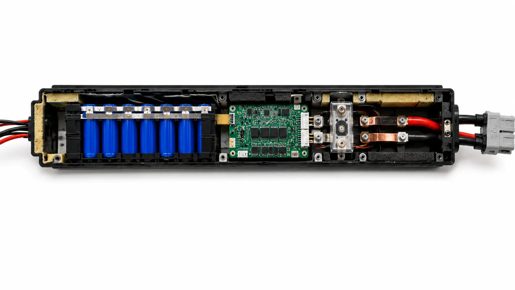
6. What Causes a Lithium-Ion Battery to Fail or Enter Thermal Runaway?
Short answer: A lithium-ion battery fails or enters thermal runaway when an electrical, thermal or mechanical fault pushes a cell past its safe limits. Typical triggers are overcharging or a wrong charge voltage, over-discharge, internal short circuits from defects or damage, external short circuits, and excessive heat. The specific risk profile depends on the cell chemistry (for example NMC versus LFP) and format, but in most real failures several weaknesses combine rather than one acting alone.
1. Selecting the Wrong Chemistry or Cell Model
A cell can be high quality and still be wrong for the application. A high-energy cell may not support repeated pulse current. A high-power cell may sacrifice runtime without adding value to a low-load product. A cell optimized for room-temperature portable electronics may not be appropriate for an outdoor, high-temperature or long-standby product.
The approved charge voltage, maximum current, cutoff voltage and temperature limits must be taken from the exact model documentation. Substituting a similar-looking cell after sample approval can change heat generation, cycle life, protection behavior and certification scope.
2. Overcharge or an Incorrect Charging Profile
Overcharge can drive the cell outside its stable electrochemical range, generate heat and gas, and increase the probability of internal failure. The charger must control voltage, current and termination according to the cell approval sheet. A nominal 3.6 V or 3.7 V label is not enough to define the correct upper voltage or charge current.
In a multi-series pack, total voltage can appear normal while one weak or imbalanced group reaches an unsafe voltage. Series-group monitoring and suitable balancing are therefore important where the configuration requires them. Protection thresholds should be coordinated with normal charger control so the BMS remains an independent safety layer rather than the routine charge terminator.
3. Severe Over-Discharge and Unsafe Recharge
Discharging below the approved minimum voltage can create permanent cell damage, increase imbalance and make subsequent charging less predictable. A deeply discharged pack should not be automatically forced back into service by a generic charger or bypass procedure.
The BMS recovery policy, pre-charge or low-voltage recovery current, cell-voltage verification and service instructions must be defined for the exact cell and product. Packs with abnormal self-discharge, reversed groups, swelling, leakage or repeated low-voltage shutdown require investigation rather than repeated reset.
4. External Short Circuit, Overload or Undersized Current Paths
A short circuit can be caused by damaged insulation, conductive debris, crushed wiring, reversed polarity, failed connectors, water ingress or an internal device fault. High current can rapidly heat cells, busbars, welds, wires, MOSFETs and connectors.
A complete short is not required to create a hazard. If the cell, conductor cross-section, connector or BMS is undersized, normal operation can produce local hot spots. Peak current, pulse duration, duty cycle, motor stall and inrush conditions must be measured in the final device rather than estimated from average power.
5. Internal Short Circuits and Latent Cell Defects
Internal shorts may originate from metallic contamination, electrode burrs, separator damage, internal misalignment, mechanical deformation or aging-related changes. These failures are difficult because a cell may pass open-circuit-voltage and capacity checks before failing later under charge, vibration or heat.
NREL notes that some field safety incidents originate from internal shorts that were not detectable or predictable at the point of manufacture. This is why cell manufacturing quality, formation, aging, self-discharge monitoring, incoming screening and pack-level consequence mitigation must work together.
6. Fast Charging and Low-Temperature Lithium Plating
Charging current that is acceptable at one temperature or state of charge may become excessive at another. At low temperature or high charge rate, lithium ions may be deposited as metallic lithium on the graphite anode instead of being safely inserted into the electrode structure. This lithium plating can accelerate degradation, increase impedance and contribute to internal-short risk.
A 2024 DOE/OSTI study describes lithium plating as an important performance, longevity and safety concern during real-world fast charging, with susceptibility affected by charge rate, operating temperature, cell design and degradation level. A safe control strategy may reduce charge current, delay charging or stop charging below a validated temperature threshold. The threshold must be model-specific.
7. High Temperature, Poor Cooling and Heat Accumulation
Cells generate heat from electrical resistance and electrochemical processes during charging and discharging. High current, aging and low state of charge can increase losses. In tightly packed modules, the hottest internal cell or connection may be much warmer than the enclosure surface.
Thermal design should evaluate the highest realistic ambient temperature, simultaneous charging and operation, blocked airflow, nearby processors or motors, enclosure material and the full duty cycle. NASA guidance notes that high storage temperature and high state of charge during storage adversely affect battery performance and life. Long exposure to heat can also reduce safety margin by accelerating aging and gas generation.
8. Cell Imbalance and Unequal Current Sharing
Series groups do not age identically. A lower-capacity group reaches charge and discharge limits first, while total pack voltage may hide the problem. In parallel groups, small differences in internal resistance and interconnection resistance can cause uneven current sharing and localized heating.
Recent modeling work has highlighted busbar interconnection resistance as an important factor affecting imbalance in lithium-ion modules and packs. Cell matching, symmetrical current paths, group-level sensing, balancing and conservative operating limits help control these effects.
9. Mechanical Damage, Compression, Swelling or Inadequate Support
Lithium-ion cells must be restrained without being crushed, pierced, bent or exposed to sharp enclosure features. Cylindrical cells require protection of wraps, terminals and vent regions. Pouch cells need controlled support for normal dimensional change and must not be trapped by concentrated pressure. Prismatic cells require suitable compression and accommodation of expansion according to the manufacturer.
Drops, vibration, fasteners, enclosure ribs and service tools can create damage that is not visible externally. Mechanical validation should use the final pack orientation and enclosure, including transport and end-product loads.
10. Moisture, Contamination and Connector or Wiring Faults
Water ingress, condensation, conductive dust, loose hardware and metallic debris can create leakage paths, corrosion or short circuits. Connector faults can also reverse polarity, connect the wrong charger or expose live contacts during service.
Battery enclosures, seals, conformal protection where appropriate, cable routing, strain relief, connector keying and cleanliness controls should reflect the real operating environment. Protection against moisture does not remove the need to evaluate venting and pressure release.
11. Incompatible BMS, Charger, Firmware or Device Integration
A battery pack can use suitable cells and still fail if the surrounding electronics are mismatched. The charger controls normal charging, the BMS monitors and interrupts abnormal electrical conditions, and device firmware may manage power demand, temperature derating or shutdown.
These layers must be validated together. A BMS threshold set too low may cause nuisance shutdowns; set too high, it may fail to protect the cell. A temperature sensor far from the hot spot may respond too late. Regenerative energy, USB power-path behavior, motor braking and operation while charging can create current flows not visible during a simple stand-alone pack test.
For custom protection thresholds, NTC configuration, wire gauge, connector selection and communication requirements, review connector, wire and PCM/BMS customization as part of the complete pack architecture.
12. Aging, Reuse, Component Substitution and Weak Change Control
Capacity loss is only one sign of battery aging. Internal resistance, self-discharge, gas generation and current-sharing behavior can also change. A pack that still powers the device may run hotter or reach voltage limits earlier than when new.
Reused cells, mixed service histories and partial cell replacement introduce uncertainty that cannot be resolved by appearance alone. In production, unauthorized changes to cells, MOSFETs, connectors, busbars, insulation or firmware can invalidate prior test results. Approved bills of material, lot traceability, revision control and supplier-change approval are essential safety controls.
7. How Thermal Runaway Develops in a Lithium-Ion Cell
Thermal runaway is a self-accelerating failure condition in which internal heat generation exceeds the cell’s ability to release heat. The initiating event may be electrical, thermal, mechanical or internal. Early signs can include abnormal temperature rise, voltage change, swelling, pressure increase, venting, odor, smoke or unusual sound, but the sequence varies by chemistry, construction and trigger.
As temperature rises, protective interfacial layers and electrolyte components can begin to decompose, gas may be generated, the separator may shrink or fail, and internal reactions can release additional heat. If the process becomes self-sustaining, disconnecting the external charger or load may no longer stop the temperature rise. NREL describes the progression from abuse conditions through exothermic reactions, gas generation and venting to rupture, flame or ejecta, with behavior dependent on chemistry, electrolyte, separator and other design factors.
Early detection is valuable but difficult. A 2024 NIST study demonstrated an acoustic model for detecting early-stage thermal-runaway events under controlled single-cell tests, illustrating the growing interest in signals beyond voltage and surface temperature. Such research does not mean every commercial pack requires acoustic monitoring; it shows that internal failure can evolve before traditional external indicators become decisive.
Important Limitation
Do not copy a thermal-runaway onset temperature, charging cutoff or emergency threshold from a generic article or research paper directly into a production BMS. Thermal response varies with chemistry, cell model, state of charge, age, trigger method, sensor location and pack confinement. Model-specific testing and an application risk assessment are required.
8. Why Cell-to-Cell Propagation and Vent Gas Are Pack-Level Risks
A single-cell failure can heat neighboring cells through direct contact, radiation, hot gas, flame, ejecta and heated interconnections. The consequence depends on cell energy, spacing, holders, barriers, cooling paths, enclosure volume and vent direction. Gas released before or during thermal runaway may also accumulate or ignite outside the initiating cell.
NREL research on compressible foams for pouch-cell modules found that pack designs require both structural support and thermal management and evaluated ways to reduce cascading thermal runaway. The broader engineering lesson is that a material or air gap cannot be treated as a universal solution. The whole propagation path must be evaluated.
State of charge affects the energy available during failure. NIST experiments on externally heated 18650 and 21700 cells found that higher state of charge shortened the available intervention window under the tested conditions. For products stored for long periods, charge strategy, thermal shutdown and early fault detection should therefore be considered together.
Concerned about thermal runaway in your Li-ion pack? Get a free safety review.
Talk to a Battery Engineer9. What a Lithium-Ion BMS Can and Cannot Do
A battery management system is a critical safety and control layer, but it is not a guarantee that a pack is safe. The design must match the cell model, series-parallel configuration, current profile, charger and temperature environment.
| BMS Function | What It Can Help Control | Important Limitation |
|---|---|---|
| Cell/group voltage monitoring | Detect overcharge, over-discharge and imbalance | Cannot prove the absence of an internal defect or measure every local electrode condition |
| Current monitoring and interruption | Limit overload and short-circuit exposure | MOSFETs, contactors, shunts and fuses must be rated for real fault energy and interruption conditions |
| Temperature monitoring | Suspend charge or discharge outside validated limits | Sensors detect only their locations; poor placement can miss internal or connector hot spots |
| Balancing | Reduce voltage drift between series groups | Cannot restore a damaged, mismatched or severely aged cell group |
| State estimation and communications | Support runtime, derating, diagnostics and controlled shutdown | Algorithms depend on accurate models, calibration and firmware behavior |
| Event logging and fault recovery | Improve service diagnosis and controlled restart | Unsafe automatic recovery can repeatedly energize a damaged pack if the fault logic is poorly defined |
The BMS should be treated as one layer in a defense-in-depth design that also includes a suitable cell, charger control, fusing or current interruption, sensor placement, insulation, thermal design, mechanical protection, manufacturing quality and end-product validation.
10. How Modern Lithium-Ion Battery Packs Reduce Fire Risk
Application-Matched Cell and Chemistry Selection
Use the exact approved cell model from a traceable source. Confirm voltage limits, current capability, charge rate, temperature range, expected life and applicable test evidence. Select chemistry and form factor according to the actual load, environment, enclosure and safety priorities rather than a single capacity number.
Controlled Charging and Power-Path Design
Use a charger or charging circuit designed for the selected cell and series count. Validate constant-current/constant-voltage behavior, termination, recharge, timer, adapter faults, operation while charging and low-temperature policy. Coordinate charger control with independent BMS protection.
BMS, Fuses and Current Interruption
Implement overcharge, over-discharge, over-current, short-circuit and temperature protection appropriate to the pack. Multi-series packs normally require group-level monitoring and balancing. Higher-energy systems may require fuses, contactors, pre-charge or cell-level current-limiting measures based on the risk assessment.
Temperature Sensing and Thermal Management
Place sensors where they can detect the hottest expected cells, connections or electronics. Evaluate heat generation and temperature uniformity under the real duty cycle, ambient temperature, enclosure and charging behavior. Apply derating or shutdown rules validated with the exact cell.
Mechanical Support, Insulation and Vent Management
Use holders, foam, compression structures, fish-paper or equivalent barriers, protected busbars, strain relief and clearance from sharp edges. Accommodate cell expansion and keep intended vent paths clear. Direct hot gas and ejecta away from neighboring cells, wiring and user-accessible areas.
Validated Interconnections and Wiring
Select tabs, nickel or copper conductors, busbars, wires and connectors for continuous current, peak current, vibration and temperature rise. Qualify welding or joining parameters and verify joint quality through visual, resistance, pull-force or destructive sampling appropriate to the process.
End-Product and Firmware Validation
Test the battery in the final device. Motor stalls, radio transmission, processors, regenerative current, charging while operating and enclosure heat can create stresses absent from a bench pack test. Verify shutdown, fault recovery, communications and charger compatibility.
Manufacturing Traceability and Change Control
Record cell lots, BMS and firmware versions, weld programs, key inspection results and finished-pack serial numbers. Lock safety-critical materials and components after approval. Require engineering review before substitutions or process changes.
A controlled battery pack production process helps maintain cell screening, assembly, protection testing, aging and final inspection from approved samples through mass production.
11. Lithium-Ion Battery Safety Review: Failure Mode and Design Response
| Failure Mode | Engineering Response | Evidence an OEM Buyer Can Request |
|---|---|---|
| Wrong cell or chemistry | Approved cell model, application review and locked sourcing route | Cell approval sheet, load profile review, approved BOM and change-control record |
| Overcharge or imbalance | Correct charger, group-level monitoring, balancing and conservative thresholds | Charge curve, BMS specification, threshold verification and abnormal-charge test |
| Low-temperature or excessive fast charging | Temperature-dependent current limits and validated charge policy | Charge map, NTC specification, low-temperature test and firmware logic |
| Short circuit or overload | Current-rated cell, conductors, protection, fuse strategy and connector | Peak-current data, short-circuit response, conductor specification and thermal test |
| Internal defect | Controlled cell source, screening, traceability and consequence mitigation | Lot records, incoming criteria, aging/self-discharge method and fault-analysis process |
| Mechanical damage or swelling | Support, compression, clearances, strain relief and enclosure validation | Mechanical drawings, drop/vibration results and inspection criteria |
| Thermal hot spot | Sensor placement, heat paths, derating and worst-case thermal validation | Thermal map, temperature-rise report and sensor-location drawing |
| Cell-to-cell propagation | Spacing, barriers, vent path, enclosure strategy and pack-level evaluation | Risk assessment and propagation or abnormal-condition test evidence where required |
| Production substitution | BOM lock, revision control and customer-approved change process | Approved parts list, revision history, deviation record and revalidation plan |
12. How Chemistry and Cell Format Change Safety Priorities
Safety comparisons should not be reduced to a simple ranking. Chemistry affects reaction behavior and voltage, while format affects mechanical support, interconnection count, heat flow and venting. The exact model and pack design remain decisive.
| Cell Format | Typical Engineering Advantage | Format-Specific Safety Priority |
|---|---|---|
| Pouch cells | High packaging efficiency and flexible dimensions | Need uniform support, swelling allowance, tab protection, edge insulation and controlled compression. See the dedicated LiPo safety guide. |
| Cylindrical cells | Rigid can, modular configuration and often directional venting | Need wrap and terminal insulation, validated welding, clear vent regions and propagation control across many cells. See the 18650 safety guide. |
| Prismatic cells | Fewer larger cells and efficient module assembly | Need suitable compression, terminal protection, busbar design, enclosure stiffness and management of greater energy per cell. |
LiFePO4 is part of the lithium-ion family, not a separate non-lithium technology. It is often selected for its cycle life and thermal stability, especially in industrial and backup applications, but it can still be damaged by overcharge, short circuit, poor BMS design or unsuitable installation. Our LiFePO4 battery safety guide examines this chemistry in greater depth.
13. Application-Specific Lithium-Ion Battery Safety Priorities
Small Electronic and Portable Devices
Wearables, GPS trackers, IoT devices and compact electronics often use small pouch cells and charge from USB or embedded adapters. Safety priorities include correct single-cell charging, tab and edge protection, swelling allowance, low standby leakage, connector polarity and temperature control in compact enclosures.
For these products, review the device requirements together with small electronic device battery applications rather than selecting a pouch cell only by dimensions and capacity.
Power Tools, Robotics and High-Current Equipment
Motor-driven products create pulse current, inrush, stall, regenerative energy, vibration and repeated charging. The cell power rating, current path, welds, connector, MOSFETs, temperature sensors and firmware shutdown must be evaluated as one system. Protection thresholds should tolerate valid pulses without allowing sustained overload.
High-current projects can use the power tool battery pack engineering guide to define voltage platform, continuous and peak current, cell format, BMS and mechanical interface.
Security, Monitoring and Industrial Equipment
These products may spend long periods in standby, operate outdoors or remain connected to a charger. Self-discharge, long-term state of charge, enclosure temperature, moisture, backup switchover, connector reliability and service intervals may be more important than headline discharge current.
Backup Power and Energy Storage
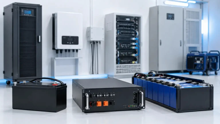
Higher-energy backup and storage systems require coordinated cell, module, BMS, contactor, fuse, thermal-management and enclosure strategies. Stationary applications may also require installation-level fire, electrical and system standards beyond cell or pack tests. Our home energy storage battery safety guide examines these residential and backup-power risks in depth.
For LFP-based backup and storage projects, browse our in-stock energy storage battery models and confirm the final compliance route before mass production.
14. Which Standards Apply to Lithium-Ion Cells and Battery Packs?
The applicable standard depends on whether the product is portable, industrial, stationary, medical, appliance-based, information-technology equipment or another regulated category. A report for one cell, pack or configuration cannot automatically be transferred to a different cell model, series-parallel arrangement, BMS or enclosure.
IEC 62133-2:2017+A1:2021 covers portable sealed secondary lithium cells and batteries under intended use and reasonably foreseeable misuse. IEC 62619:2022 addresses secondary lithium cells and batteries for industrial applications, including stationary applications. The UN Manual of Tests and Criteria, Sub-section 38.3, provides transport test requirements for lithium cells and batteries. UN 38.3 supports shipment compliance; it is not a complete end-product safety certification.
UL Solutions identifies UL 1642 for lithium cells and UL 2054 for household and commercial battery packs among the standards used in battery safety testing, with additional standards selected by end-product application. The final certification route should be confirmed with the customer, test laboratory or market-access specialist before tooling and mass production.
| Reference | Primary Purpose | Buyer Reminder |
|---|---|---|
| UL 1642 | Lithium-cell safety evaluation | Cell-level evidence does not replace pack or end-product evaluation. |
| UL 2054 | Household and commercial battery packs | Scope and acceptance depend on the battery and final product. |
| IEC 62133-2 | Portable sealed secondary lithium cells and batteries | Confirm exact edition, model coverage and national adoption. |
| IEC 62619 | Industrial secondary lithium cells and batteries, including stationary applications | Consider for industrial, UPS, AGV, telecom and related applications where applicable. |
| UN 38.3 | Transport testing for lithium cells and batteries | Required for shipping pathways but not a complete product safety approval. |
| Application-specific standards | Medical devices, appliances, ICT equipment, tools, mobility or energy storage | Select by final device, installation and target market, not by battery chemistry alone. |
Buyers can review THOR Power’s battery certificates and compliance documents while confirming that the report holder, tested model, cell, BMS and configuration match the production battery.
15. Common OEM Mistakes in Lithium-Ion Battery Pack Projects
Selecting by Voltage and Capacity Alone
Two packs can share the same voltage and capacity while using cells with very different current limits, temperature ranges, cycle life and thermal behavior. The load profile and charger must be reviewed before a cell is approved.
Treating the BMS as the Charger
The BMS is normally an abnormal-condition protection layer, not the primary controller for every charge cycle. Repeatedly charging until the BMS trips can stress cells and create inconsistent termination.
Using One Temperature Sensor in the Easiest Location
A convenient sensor on the enclosure or BMS may not detect the hottest internal cell, connector or MOSFET. Sensor placement must follow the thermal map and fault scenarios.
Approving a Sample Without Locking Safety-Critical Parts
The cell model, BMS revision, MOSFET, NTC, connector, wire, conductor, insulation and firmware should not change without engineering review. An externally identical pack can behave differently after one internal substitution.
Using a Certificate From a Similar Battery
Similar voltage or capacity does not prove report coverage. UN 38.3, IEC, UL and customer approvals must be checked against the exact model and configuration.
Designing the Enclosure Before the Battery Architecture
Late changes to cell format, support, vent path, sensor location or wire exit can force enclosure redesign or reduce safety margins.
Testing the Battery Without the Final Device
Bench tests may miss motor stalls, charging while operating, firmware faults, processor heat, regenerative current, connector misuse and enclosure temperature.
Ignoring Aging and Storage Conditions
A pack validated when new may run hotter after resistance increases. Long storage at high state of charge or temperature can accelerate degradation and should be included in life planning.
16. How OEM Buyers Should Evaluate a Lithium-Ion Battery Pack Supplier
A supplier should be evaluated by its engineering review, evidence and production controls rather than only by pack price, claimed capacity or a generic certificate. Buyers should ask for the following:
- Exact cell manufacturer, model and approved sourcing route, including lot identification and change-control rules.
- Cell approval sheet covering charge voltage, discharge cutoff, current capability, temperature range and applicable test evidence.
- Incoming-control methods for appearance, open-circuit voltage, internal resistance, capacity, self-discharge or batch consistency according to project risk.
- Series-parallel design, group-monitoring and balancing strategy where applicable.
- BMS protection thresholds, MOSFET or contactor rating, fuse strategy, NTC value and sensor placement.
- Conductor sizing, connector rating, joining-process qualification, insulation standards and joint-verification methods.
- Thermal validation using the real load profile, charger, enclosure, ambient range and aging allowance.
- Mechanical validation for support, compression, drop, vibration, wire exits and service access.
- Sample testing in the customer’s device before the charger, enclosure and certification route are frozen.
- Pack serial numbers, cell-lot mapping, BMS and firmware revision, final test records and corrective-action process.
17. What to Send Your Battery Supplier Before Sample Development
A battery supplier can recommend a safer and more stable solution when the first inquiry includes real engineering context. The following information reduces assumptions and shortens the path from quotation to a production-representative sample:
- Device type, target market, operating environment and expected safety, transport or end-product standards.
- Nominal voltage, maximum charge voltage, cutoff requirement and preferred series-parallel arrangement if already defined.
- Runtime target, standby current, average current, continuous current, peak current, pulse duration and regenerative current where relevant.
- Battery-space drawing, enclosure material, cell orientation, support method, ventilation or vent path, heat sources and wire exit.
- Charging input, charge current, adapter specification, USB or dock behavior, power-path design and whether the product operates while charging.
- Connector model, wire length, polarity, NTC requirement, communication protocol, BMS functions and labeling needs.
- Ambient and storage temperature range, humidity, vibration, expected cycle life, standby period and service interval.
- Sample approval criteria, final-device test conditions, expected quantity and components that must remain unchanged for mass production.
Teams with drawings or an existing prototype can request a battery solution and attach the current load profile, battery space, charger information and target-market requirements.
18. How THOR Power Supports Safer Custom Lithium-Ion Battery Pack Projects
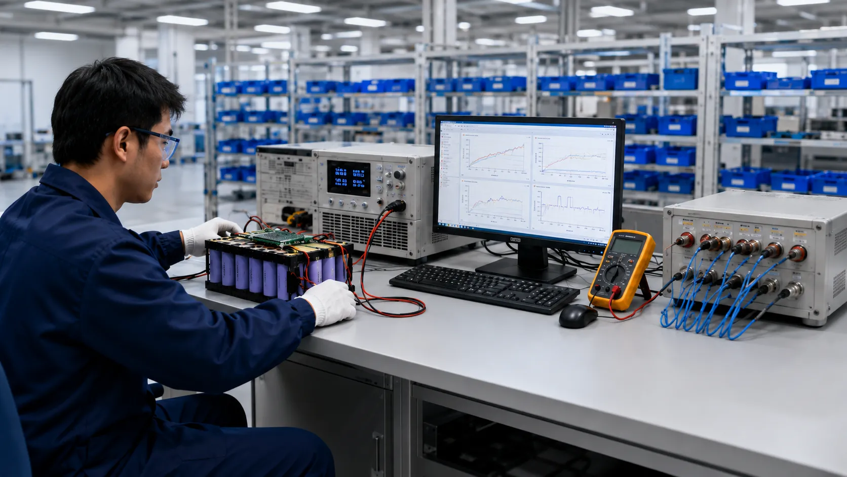
THOR Power supports custom lithium-ion battery pack development across compact pouch batteries, cylindrical-cell packs, industrial packs and LiFePO4 backup or energy-storage solutions. The engineering review begins with the application rather than a preselected catalog battery.
The project workflow is designed to close the gap between a working prototype and stable production: requirement review, chemistry and cell-model selection, series-parallel design, PCM/BMS matching, connector and wire confirmation, pack-structure review, sample build, final-device testing, documentation review and mass-production control.
For approved projects, THOR Power can help define controlled items such as cell model, lot rules, BMS and firmware version, MOSFET rating, fuse, NTC value and location, connector, wire gauge, conductor material, insulation, support or foam, enclosure interface, labeling, packaging and final test items. These details matter because batteries that look identical externally can behave differently after an internal component or process changes.
Before recommending a pack direction, the review covers battery chemistry, voltage, capacity, continuous and peak current, pulse duration, charger, temperature range, available space, connector, wire, PCM/BMS, mechanical support, insulation, operating environment, certification needs and production feasibility.
Production quality controls can include cell appearance and batch review, open-circuit-voltage and internal-resistance checks, capacity verification according to project requirements, cell matching, joining inspection, insulation and polarity checks, PCM/BMS functional testing, charge-discharge validation, aging and final electrical inspection.
For transport documentation, THOR Power can support UN 38.3 and SDS/MSDS planning according to the exact battery model and shipment requirements. Market-specific safety and end-product certification scope should be confirmed for the final battery and device before certification claims are published.
The objective is not to suggest that one chemistry, BMS or certificate eliminates every risk. The objective is to build multiple, verifiable safety layers into cell selection, charging, electrical protection, thermal and mechanical design, device integration and manufacturing control from the beginning.
19. When to Involve THOR Power
The best time to involve THOR Power is before the enclosure, charger, connector and certification route are fully locked. Early review gives the development team more freedom to balance runtime, current capability, dimensions, heat, cycle life, documentation, cost and long-term supply.
If the product already has a prototype, provide the load profile, battery space, charger details, target market and current pack design. THOR Power can review whether the direction is suitable or whether a different chemistry, form factor, BMS or structural solution should be considered.
Planning a Custom Lithium-Ion Battery Pack?
Send us your application, load profile, runtime target and space constraints. Our engineers will recommend the right chemistry, cell format, configuration and BMS protection — with samples, UN38.3/MSDS support, and stable mass production.
Talk to a Battery EngineerKey Takeaways
- Lithium-ion is a family of chemistries and cell formats; it is not a complete battery specification.
- The exact cell model, charging profile, current demand, temperature range and pack configuration must be reviewed together.
- A BMS is essential in many packs, but it cannot replace correct cell selection, charger control, thermal design, mechanical protection or manufacturing quality.
- Fast charging and low-temperature charging require model-specific limits because lithium plating can reduce life and increase safety risk.
- Internal shorts may not be predictable through simple incoming checks, so pack-level consequence mitigation and traceability remain important.
- Temperature sensors must be placed according to real hot spots; one convenient sensor may not represent the complete pack.
- Pouch, cylindrical and prismatic cells create different mechanical, interconnection and venting priorities.
- UN 38.3, IEC 62133-2, IEC 62619, UL 1642 and UL 2054 serve different purposes. Documentation must match the exact model and end product.
- The safest custom lithium-ion battery pack is designed around the real device, charger, enclosure, environment, life requirement and mass-production controls.
Conclusion
Lithium-ion batteries remain one of the most capable rechargeable power technologies available to product developers, but their broad name should not be confused with automatic safety or interchangeability. Safe performance depends on the exact chemistry and cell model, correct charging, coordinated BMS and current interruption, reliable interconnections, temperature control, mechanical protection and disciplined production.
The most important shift for OEM buyers is to evaluate the complete battery architecture. A cell can pass cell-level testing and still be integrated into an unsafe pack. A pack can also pass a short bench test while failing under the final device’s heat, pulse current, charger behavior or service conditions.
Early engineering review provides the best opportunity to balance energy, power, dimensions, cycle life, compliance, cost and long-term supply without creating late-stage redesign risk. THOR Power supports this process with application review, cell and chemistry selection, PCM/BMS integration, connector and structure customization, sample testing, documentation planning and production quality control. Explore our lithium-ion battery pack solutions to start the conversation with a concrete product direction.
FAQ: Lithium-Ion Battery Safety
What makes a lithium-ion battery pack safe enough for an OEM product?
A suitable pack uses the exact cell model inside approved voltage, current, temperature and mechanical limits, then adds compatible charging, protection electronics, thermal design, insulation, enclosure support, manufacturing control and final-device validation. The term lithium-ion alone does not prove that a battery is suitable for a specific device.
When can a lithium-ion cell vent, ignite or rupture?
Severe abuse or defects can lead to forceful venting, ignition or rupture. Initiating conditions can include overcharge, short circuit, external heat, mechanical damage, internal defects, incompatible charging, lithium plating and unsafe pack integration. Good engineering reduces both the probability and the consequence of these failures.
How is a LiPo pouch cell related to lithium-ion battery safety?
Lithium-ion is the broader rechargeable battery family. LiPo commonly refers to lithium-ion cells made in a flexible pouch format and, in commercial usage, does not automatically identify a different cathode chemistry. Pouch-cell safety depends heavily on swelling allowance, support, tab protection, edge insulation and compression control.
Is a BMS enough to make a lithium-ion battery pack safe?
No. A BMS is one safety layer. It cannot replace correct cell selection, charger control, conductor sizing, fusing strategy, sensor placement, thermal management, mechanical protection, production quality or change control. Most multi-cell rechargeable lithium-ion packs still require a PCM or BMS appropriate to the configuration and application.
What charger information should an OEM provide before sample development?
Provide input source, charge voltage, charge current, termination method, adapter behavior, USB or dock details, operation while charging, low-temperature policy and any power-path or backflow conditions. A connector that fits does not prove electrical compatibility.
Is fast charging safe for lithium-ion batteries?
Fast charging can be safe when the cell is designed for the charge rate and the control system adjusts current according to temperature, state of charge and cell limits. Excessive charge rate, especially at low temperature, can promote lithium plating, heating and accelerated aging.
Why is charging a cold lithium-ion battery risky?
At low temperature, lithium transport and insertion into the graphite anode become more difficult. If charging current is too high, metallic lithium can plate on the anode. The safe response may be to reduce current, preheat or stop charging, depending on the cell model.
Can an old lithium-ion battery become less safe?
Aging can increase internal resistance, heat generation, imbalance and self-discharge even before the battery stops working. A safe life strategy should include capacity and temperature limits, service criteria, fault logging where appropriate and replacement instructions.
How should buyers compare NMC, NCA and LiFePO4 safety?
Compare them by exact model data and application context, not by chemistry label alone. LiFePO4 often provides higher thermal stability and long cycle life, but it still needs correct charging, BMS design, enclosure validation and compliance planning.
Which warning signs can suggest a lithium-ion battery is entering a dangerous condition?
Warning signs may include abnormal temperature rise, swelling, odor, smoke, venting, voltage change, unusual sound or repeated protection trips. These signs are not always present or early enough. Possible triggers include short circuits, overcharge, excessive current, external heat, mechanical damage, lithium plating and latent manufacturing defects.
Is UN 38.3 the same as IEC 62133-2, IEC 62619 or UL certification?
No. UN 38.3 addresses transport testing. IEC 62133-2 addresses portable sealed secondary lithium cells and batteries, while IEC 62619 covers industrial secondary lithium cells and batteries. UL 1642 and UL 2054 address different cell and battery-pack safety scopes. Additional end-product standards may apply.
How should an OEM choose a lithium-ion battery pack manufacturer?
Evaluate cell sourcing, engineering review, charging and BMS capability, thermal and mechanical design, joining and insulation controls, sample testing, traceability, documentation support, change control and long-term production consistency. Do not evaluate safety only by price, capacity or a generic certificate.
References
- NREL. Defining the State of Safety (SOS) for Lithium-Ion Batteries in EVs: A Discussion.
- NREL. Large Lithium Ion Battery Technology and Application R&D.
- NIST (2024). Development of a Robust Early-Stage Thermal Runaway Detection Model for Lithium-Ion Batteries.
- DOE/OSTI (2024). Advancing Li-Plating Detection: Motivating a Multi-Signal Approach.
- NASA. Guidelines on Lithium-Ion Battery Use in Space Applications.
- NREL. Integration Issues of Cells into Battery Packs.
- NREL / OSTI. Compressible Battery Foams to Prevent Cascading Thermal Runaway in Li-Ion Pouch Batteries.
- DOE/OSTI. Physics-Based Analysis of Cell Imbalances and Aging in Lithium-Ion Modules and Packs.
- International Electrotechnical Commission. IEC 62133-2:2017+A1:2021.
- International Electrotechnical Commission. IEC 62619:2022.
- UNECE. UN Manual of Tests and Criteria, Revision 8 — Sub-section 38.3.
- UL Solutions. Battery Certification Services for Cell Manufacturers.
- UL Solutions. Battery Safety Testing and Certification.
- Tam et al., NIST / Applied Thermal Engineering (2026). Examining Safe Intervention Windows for 18650 and 21700 Lithium-Ion Batteries under Heat Interruption Experiments.


Dr. Maximilian Weber is THOR Power's Chief Scientist and a senior expert in lithium battery technology. His technical review focuses on battery safety, performance optimization, energy density and custom battery solution development.
Last technical review: July 2026

Victor Xiong holds a Master's degree from The Chinese University of Hong Kong, Shenzhen. He leads THOR Power's OEM Division and focuses on custom battery solutions for global device brands, product developers and industrial customers.