High-Power LiPo Applications

Custom High-Discharge LiPo Batteries for High-Power Applications

THOR Power develops custom high-discharge LiPo batteries for drones, UAVs, RC models, robotics, jump starters and other high-power portable equipment. Each battery is engineered around the actual continuous current, peak load, pulse duration, voltage, size, weight and connector requirements of your device.

High Discharge Custom Size Lightweight Design Peak Current Review OEM / ODM

Final discharge capability is confirmed according to the actual load, battery configuration and sample validation — not C-rate alone.

High-Discharge LiPo Basics

What Is a High-Discharge LiPo Battery?

A high-discharge LiPo battery, also commonly described as a high-rate or high C-rate LiPo battery, is designed to deliver higher current than a standard energy-focused pouch cell while maintaining acceptable voltage stability and temperature behavior under load.

For drones, UAVs, RC models, robotics and other motor-driven equipment, battery capacity alone does not determine whether a cell can power the device successfully. The battery must also be able to supply the required continuous current and peak current without excessive voltage sag, temperature rise or premature protection cutoff.

C-rate is a useful starting point for estimating discharge current, but it should not be treated as the only design parameter. Two LiPo batteries with the same capacity can behave very differently under the same load because of differences in cell chemistry, electrode design, internal resistance, tabs, pack configuration and thermal conditions.

For an OEM project, the finished battery must therefore be evaluated as a complete electrical system — from the pouch cell and welding tabs to the PCM or BMS, wire gauge, connector and the actual load profile of the device.

High C-rate does not automatically mean the battery is suitable for your device.

The required current, how long that current lasts, the acceptable voltage drop, operating temperature and battery dimensions must all be considered before a final cell or pack configuration is selected.

01
Continuous Current Current the battery must sustain during normal operation.
02
Peak Current Short-term load during startup, acceleration or power bursts.
03
Pulse Duration How long the battery must maintain the requested peak load.
04
Thermal Behavior Voltage sag, internal resistance and temperature rise under load.
Capacity vs Power

High Capacity Does Not Mean High Discharge Capability

Battery capacity tells you how much charge a cell can store. It does not tell you how much current that battery can safely and repeatedly deliver. A 5,000mAh LiPo designed for long runtime may have very different electrical behavior from a 5,000mAh LiPo engineered for high-power loads. If runtime and stored energy are the primary design goals, explore our large-capacity LiPo batteries.

Example 01
Same battery capacity: 5,000mAh / 5Ah
5A Equivalent to 1C
Moderate Continuous Load

A 5A continuous load on a 5Ah battery corresponds to a 1C discharge rate. Many energy-focused LiPo designs can operate in this general range, subject to the actual cell specification and pack design.

Example 02
Same battery capacity: 5,000mAh / 5Ah
25A Equivalent to 5C
High Continuous Load

At 25A continuous current, the project becomes much more dependent on cell resistance, electrode design, tabs, welding, temperature rise and the current capability of the entire battery pack.

Example 03
Same battery capacity: 5,000mAh / 5Ah
50A Peak Equivalent to 10C peak
High Peak-Power Demand

A 50A peak load requires evaluation of both current magnitude and pulse duration. A short acceleration pulse and a long high-current event can impose very different electrical and thermal stresses.

!
These values describe the load requirement — not a guaranteed battery rating.

A calculation such as 5Ah × 10C = 50A does not mean that every 5,000mAh LiPo battery can safely deliver 50A. The real current capability must be confirmed from the selected cell, discharge time, acceptable voltage sag, temperature rise and finished pack design.

What Changes as the Required Current Increases?

Higher current affects much more than the pouch cell itself. The complete current path must be designed around the real load.

01 Cell Design Chemistry, electrode structure and internal resistance influence usable discharge performance.
02 Tabs & Welding Current must pass through cell tabs and welded connections without excessive resistance or heating.
03 PCM / BMS Protection circuitry must support the required continuous and peak current without nuisance cutoff.
04 Wire & Connector Wire gauge and connector contact resistance become increasingly important as current rises.
05 Thermal Behavior Voltage drop, heat generation and enclosure conditions must be checked under realistic operating loads.
The correct starting point is your device load — not the battery capacity alone.

For a custom high-discharge LiPo project, THOR Power evaluates continuous current, peak current, peak duration, battery size, voltage, weight and thermal conditions together before recommending the cell and pack configuration.

High-Power Applications

High-Discharge LiPo Battery Applications

High-discharge LiPo batteries are especially useful where a device requires a combination of high current, low weight, compact dimensions and rapid power delivery. The correct battery design depends on the actual load profile rather than the application name alone.
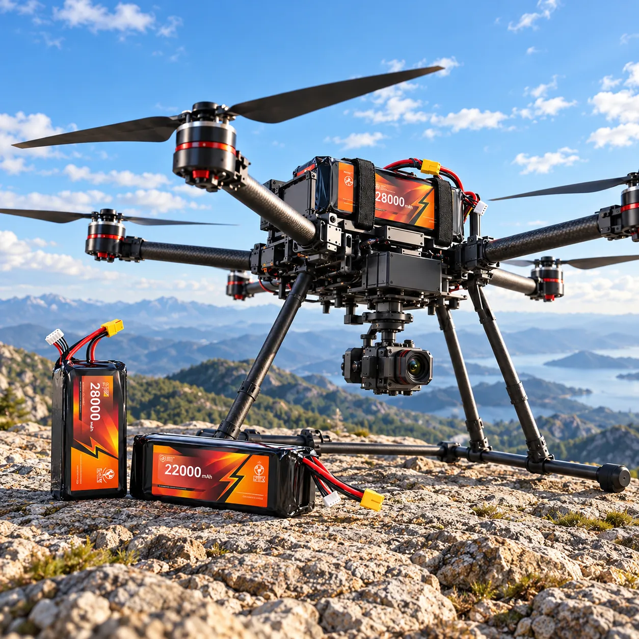
RC / FPV Image High-discharge LiPo batteries for RC models and FPV systems
02
Burst + Continuous

RC Models & FPV Systems

RC cars, aircraft and FPV systems can create large transient loads during rapid acceleration and throttle changes. A suitable RC LiPo battery must deliver repeated current bursts while maintaining usable voltage.

Engineering Focus
  • Acceleration and burst current
  • Voltage sag during throttle changes
  • Pack weight and installation space
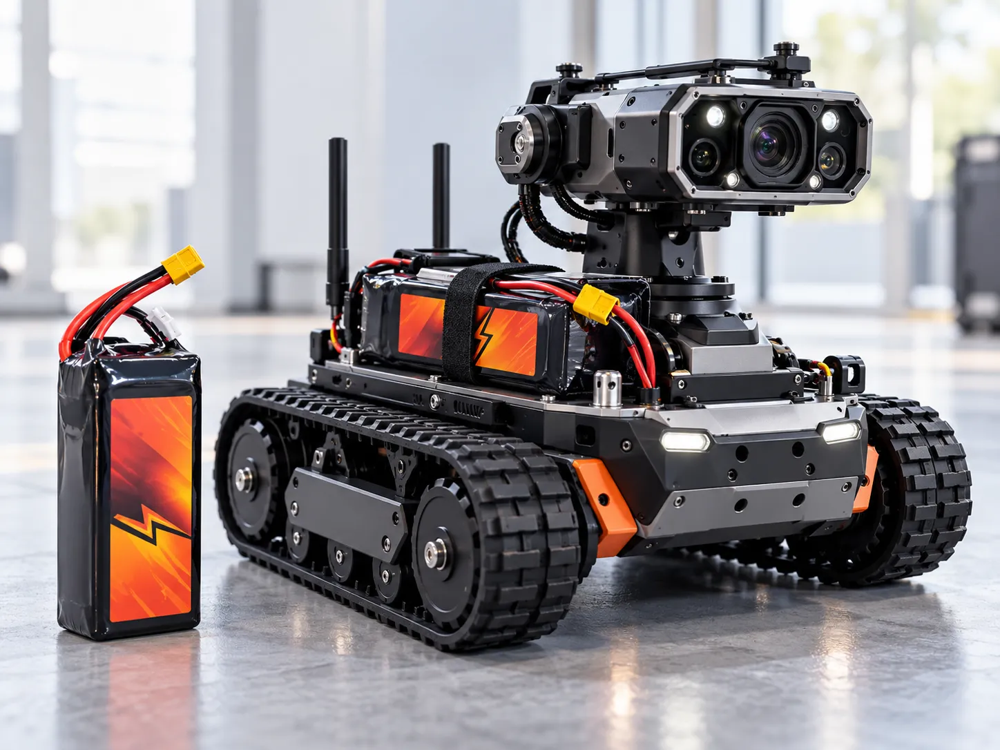
Robotics Image High-discharge LiPo battery for mobile robotics and inspection robots
03
Motor-Driven

Robotics & Mobile Robotic Systems

Mobile and inspection robots often combine sustained electrical demand with short startup or acceleration peaks. The battery should be designed around the real motor load and operating duty cycle.

Engineering Focus
  • Motor startup and acceleration current
  • Continuous operating load and runtime
  • Peak duration and thermal environment
Jump Starter Image High-discharge LiPo battery used in an automotive jump starter system
04
High-Pulse Load

Automotive Jump Starter Batteries

Portable jump starters require very high current for short periods. The design must consider pulse duration, internal resistance, voltage sag and the complete high-current path , not peak current alone.

Engineering Focus
  • Short-duration high pulse current
  • Pulse duration and recovery interval
  • Low-resistance tabs, wiring and terminals
Beyond Standard Categories

Other High-Power Portable Equipment

Pumps · Actuators · Portable Motors · Industrial Electronics · Emergency Equipment

Not every high-current project fits a standard application category. If your equipment has an unusual load profile, voltage requirement or mechanical constraint, the battery can be reviewed as a custom high-power project.

Review Required Parameters
The application name is only the starting point.

Two drones or two robots can require completely different batteries. For engineering review, provide the continuous current, peak current, peak duration, voltage, battery space and target runtime of the actual device.

Get a Battery Solution
Engineering Factors

What Determines Whether a LiPo Battery Can Handle Your Load?

A high-discharge LiPo battery should not be selected from C-rate alone. Real capability depends on how continuous current, peak current, pulse duration, voltage sag, internal resistance and temperature behave under the actual operating conditions of your device.

Start With the Current the Device Actually Needs

For high-power equipment, the first question is not simply “What C-rate do you need?” It is how much current the device draws, when it draws that current, and how long the demand lasts.

A
Continuous Current

This is the current the battery must support during sustained normal operation while maintaining acceptable voltage and temperature.

Example: a mobile robot drawing 12A during normal movement.
↑
Peak Current

Motors, propellers and actuators can demand substantially more current during startup, takeoff or acceleration than during steady operation.

Typical situations: drone takeoff, RC acceleration or motor startup.
ms
Peak Duration

Peak current has little engineering meaning without time. A 30A load for 0.2 seconds and a 30A load for 10 seconds create very different electrical and thermal stress.

Always specify both peak current and approximate peak duration.

High-Discharge Capability Depends on the Entire Current Path

A high-power pouch cell alone does not create a high-power finished battery. Every component between the cell and the device must support the required current with acceptable resistance and temperature rise.

01 LiPo Cell
→
02 Cell Tabs
→
03 Welding
→
04 PCM / BMS
→
05 Wire & Connector
→
06 Device Load
!
The weakest component can limit the entire battery pack.

A suitable high-discharge cell can still be limited by an undersized wire, high-resistance connector, weak weld or protection circuit that cannot support the required continuous or peak current.

✓
Design around the real load profile — not a C-rate label.

For engineering review, the most useful inputs are continuous current, peak current, peak duration, operating voltage, battery dimensions, weight limit and operating temperature. These provide a stronger basis for selecting the correct LiPo cell and pack architecture than capacity or C-rate alone.

Battery Selection

Standard LiPo vs High-Discharge LiPo vs 18650/21700

High-current devices do not all require the same battery architecture. The best choice depends on the balance between power demand, available space, weight, runtime, mechanical structure and pack configuration. High-discharge pouch cells are especially useful where both high power and flexible geometry are important, while cylindrical cells can be a strong option for structured multi-cell battery packs.

Energy & Size Focus

Standard LiPo

Best suited to compact electronics where custom dimensions, lightweight construction and energy density are more important than very high discharge current.

Common Fit IoT devices, trackers, compact medical electronics, wearables and other space-constrained products.
Power + Flexible Geometry

High-Discharge LiPo

Designed for applications that require stronger continuous or peak current while retaining the low weight and customizable flat form factor of pouch-cell technology.

Common Fit Drones, UAVs, RC systems, robotics, jump starters and specialized high-power portable equipment.
Structured Pack Design

High-Drain 18650 / 21700

Cylindrical cells are well suited to standardized pack structures, especially where multiple cells can be arranged in series and parallel to achieve the required voltage, capacity and current.

Common Fit Power tools, industrial equipment, larger robotic systems and structured multi-cell battery packs.
Design Requirement Standard LiPo High-Discharge LiPo High-Drain 18650 / 21700
Flexible Battery Dimensions Excellent for thin, compact and custom-shaped spaces. Excellent where custom pouch dimensions and high power are both required. Cell diameter and length are fixed; pack geometry depends on cell arrangement.
High-Current Capability Generally intended for low-to-moderate loads depending on the selected cell. Designed specifically for stronger continuous and peak-current requirements. High-drain cylindrical cells can provide strong current in properly engineered pack configurations.
Power-to-Weight Priority Good where energy density and low mass are priorities. Strong fit for weight-sensitive high-power applications. Depends on cell count, holders, interconnects and overall pack structure.
Pack Structure Single pouch cell or custom series / parallel pouch pack. Single or multi-cell pouch configuration optimized around load and weight. Well suited to modular series / parallel pack construction.
Drone / UAV Suitable mainly for lower-power or compact aerial electronics. Typical high-power choice where low weight and rapid current delivery matter. Possible for some platforms, but geometry and pack weight must be evaluated carefully.
Robotics Suitable for compact robots with moderate current demand. Strong option for compact or weight-sensitive motor-driven systems. Strong option for larger structured robotic battery packs.
Power Tools Usually not the primary choice for high-load tool applications. Possible for specialized designs where pouch geometry is useful. Common solution for structured high-current tool battery packs.

A Better Way to Choose the Battery Architecture

Start with the engineering constraints of the device rather than selecting a cell format first.

01
Define the Load Identify continuous current, peak current, peak duration and operating voltage.
02
Define the Mechanical Limits Confirm maximum battery dimensions, weight limit and available enclosure geometry.
03
Select the Cell Architecture Compare pouch and cylindrical solutions based on the combined electrical and mechanical requirements.
There is no universally “best” battery format.

The correct solution depends on the project. If thin geometry, low weight and high discharge are the dominant constraints, a high-discharge LiPo may be appropriate. If the device can accommodate a structured cylindrical pack, high-drain 18650 or 21700 cells may offer a better system architecture.

OEM / ODM Engineering

Custom High-Discharge LiPo Battery Design Options

A custom high-discharge LiPo battery is more than a pouch cell. THOR Power can configure the electrical specification, cell architecture, current path, protection system and mechanical interface around the actual requirements of your device.
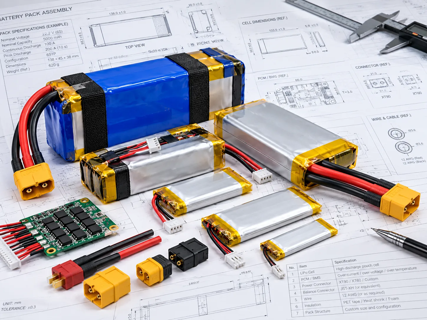
Custom Pack Engineering Image
Custom high-discharge LiPo battery pack with high-current wiring and connectors
Engineered as a Complete Pack

The Cell Is Only One Part of the Design

Final battery performance depends on how the cell, pack structure, protection components and electrical interface work together inside the actual device.

V/A
Electrical Configuration Voltage, capacity, continuous current and peak load.
S/P
Cell & Pack Architecture Cell dimensions, series / parallel layout and pack orientation.
A→
High-Current Interface Tabs, welding, wire gauge, connector and balance wiring.
T°
Protection & Thermal PCM/BMS, current thresholds, NTC and operating temperature.
V/A

Electrical Requirements

Nominal Voltage Single-cell or multi-series configuration matched to the device.
Capacity / Runtime Balanced against available space, runtime, weight and power demand.
Continuous Current Sustained discharge capability matched to the normal device load.
Peak Current Short-term requirement during startup, acceleration or load peaks.
Peak Duration Pulse time reviewed together with current and thermal behavior.
S/P

Cell & Pack Architecture

Cell Dimensions Thickness, width and length selected around the available space.
Series Configuration Multi-series layouts for higher operating voltage.
Parallel Configuration Parallel cells where additional capacity or current is required.
Pack Orientation Cell placement, wire exit and pack geometry adapted to the enclosure.
Weight Target Important for drones, UAVs, RC systems and mobile robotics.
A→

High-Current Connection Path

Cell Tabs Tab design selected around the expected current.
Welding Interconnect resistance and mechanical reliability reviewed.
Wire Gauge Sized for current, wire length, voltage drop and installation.
Connector Current-rated connector matched to the device interface. See our Battery Connector Guide .
Balance Lead Balance wiring available for multi-series charging architectures.
T°

Protection & Thermal Design

PCM / BMS Protection architecture matched to voltage, current and pack layout.
Overcurrent Setting Threshold selected to allow legitimate device peaks.
NTC / Temperature Temperature sensing integrated where required by the system.
Insulation Protective materials selected for the mechanical environment.
Operating Temperature Ambient and device temperatures included in engineering review.
Custom Design Process

Electrical Requirements and Mechanical Constraints Must Be Designed Together

Higher current can affect cell size, pack structure, wiring, connectors and temperature. A practical design balances these constraints rather than maximizing one specification alone.

01 Device Load Voltage, continuous current, peak current and pulse duration.
→
02 Mechanical Space Maximum thickness, width, length and battery weight.
→
03 Battery Architecture Cell selection, series / parallel layout and current path.
→
04 Sample Validation Verify fit, voltage behavior, current delivery and temperature.
Customization should solve the device problem — not simply change the battery label.

THOR Power provides custom battery solutions covering cell dimensions, voltage, capacity, series / parallel configuration, current capability, PCM/BMS, NTC, wire gauge, connector, balance lead, insulation, wire exit direction and OEM labeling . Final specifications are confirmed through engineering review and sample validation before mass production.

Engineering Review

What We Need to Design Your High-Discharge LiPo Battery

A useful engineering review does not require a complete battery specification. Start with what you already know about the device. For high-power projects, load current, available battery space, voltage and runtime give us the strongest starting point.

A
Start with the three critical load parameters
Continuous Current Peak Current Peak Duration

“30A” alone is not enough. We need to know whether that current is continuous, intermittent or a short startup pulse.

A/V
Group 01

Application & Electrical Load

01
Application Drone, UAV, RC system, robot, jump starter, motor-driven equipment or another high-power device.
02
Continuous Current Critical Current normally required during sustained operation.
03
Peak Current & Duration Critical Maximum current and how long each peak lasts, for example 30A for 2 seconds.
mm
Group 02

Battery Space & Energy

04
Maximum Battery Dimensions Maximum thickness × width × length, including installation clearance where known.
05
Nominal Voltage Required system voltage or existing 1S / 2S / 3S / 4S pack configuration.
06
Capacity / Runtime Target Target mAh / Wh or expected operating time under the real load.
I/O
Group 03

Interface & Operating Conditions

07
Connector & Wire Connector model, polarity, wire gauge and wire length. Photos or drawings are also useful.
08
Charging Method Charger voltage, charge current and existing charging / balancing architecture.
09
Operating Temperature Expected ambient temperature and nearby device heat.
OEM
Group 04

Mechanical & Project Requirements

10
Weight Limit Maximum preferred battery weight, especially for mobile or aerial equipment.
11
Protection Requirements PCM/BMS, NTC, balance leads or other monitoring requirements.
12
Estimated Order Quantity Prototype quantity and expected production volume.
Example Engineering Request

A Useful RFQ Can Be Very Short

You do not need a finished battery specification. A short message containing the core electrical and mechanical requirements is enough for an initial engineering review.

Application Mobile inspection robot
Voltage 7.4V nominal / 2S
Battery Space Maximum 100 × 60 × 14mm
Continuous Load 8A
Peak Load 15A for approximately 3 seconds
Runtime Target Approximately 60–90 minutes
Connector To be confirmed
Do not have every parameter yet?

That is not a problem. Send the information already available — device drawings, battery compartment dimensions, motor or controller specifications, existing battery photos or connector details. The remaining parameters can be clarified during engineering review.

Have a high-discharge battery project?

Send the available dimensions, voltage and load requirements. We will review the project before recommending a cell or pack configuration.

Get a Battery Solution
Development Process

From Load Requirements to Sample Validation

A high-discharge battery project should move from real device requirements to verified sample performance before production. The goal is not simply to build a battery that matches nominal specifications, but to confirm that the finished pack performs correctly under the actual device load.

Stage 1 · Define

Define the Electrical and Mechanical Requirements

The project starts with the device, available battery space and actual current profile — not with a battery model number.

01
Requirement Review

Confirm application, voltage, battery space, runtime, continuous current, peak current and peak duration.

02
Cell Selection

Evaluate suitable pouch-cell dimensions, discharge characteristics, internal resistance and chemistry.

03
Pack Design

Define series / parallel layout, protection, tabs, wiring, connector and mechanical arrangement.

Stage 2 · Build & Validate

Prototype, Test and Verify the Battery in the Real System

This is the critical stage where the proposed battery architecture is converted into measurable sample performance.

04
Prototype Build

Produce engineering samples using the proposed electrical and mechanical configuration.

Engineering Sample
05
Load Testing

Check voltage behavior, current delivery, protection response and temperature rise under representative operating loads.

Critical Verification
06
Device Validation

Confirm mechanical fit, runtime and electrical performance inside the actual device or prototype system.

Customer Validation
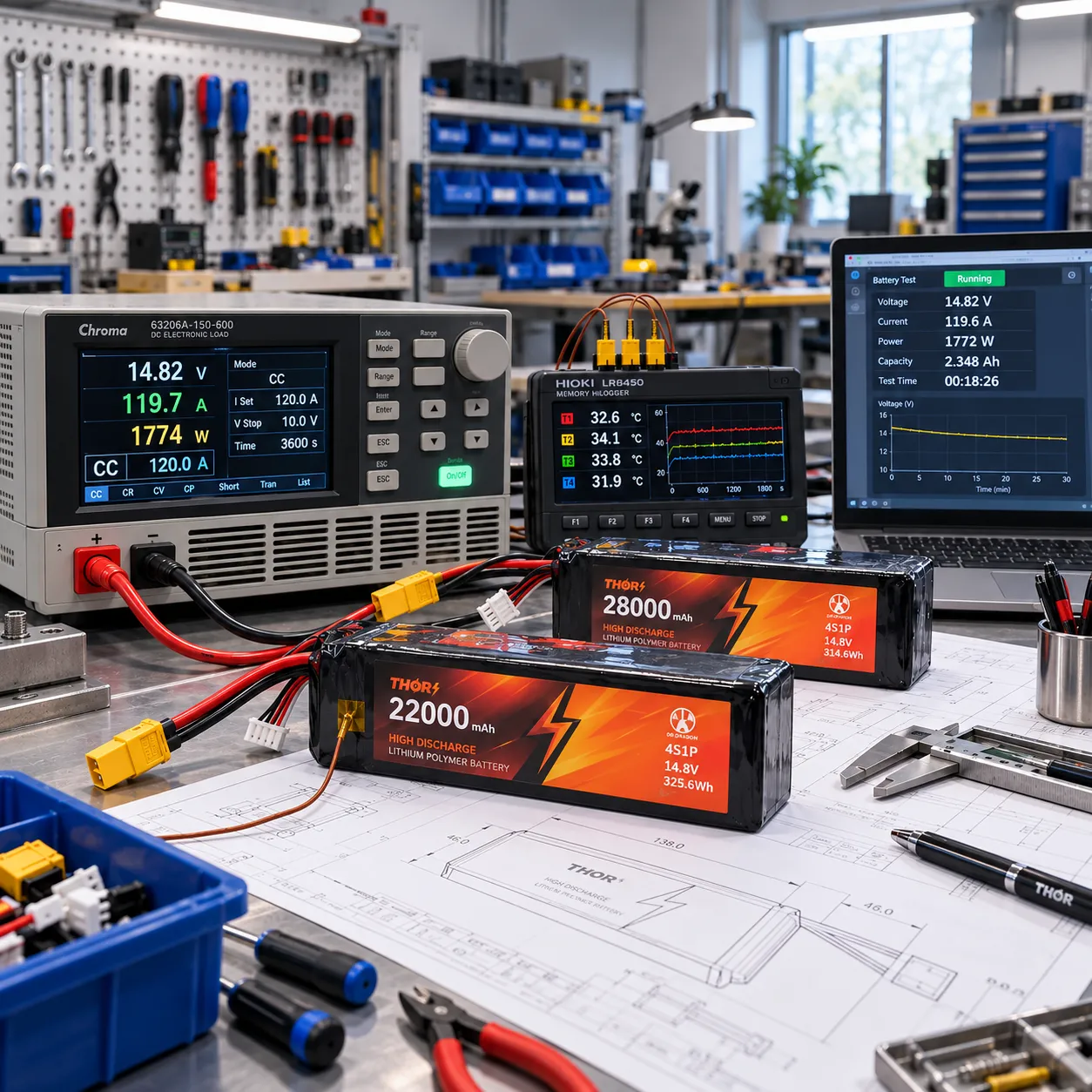
Load Testing / Sample Validation Image
High-discharge LiPo battery prototype undergoing electrical load and temperature testing
Sample Verification

What Should Be Checked During Sample Validation?

A sample must be evaluated as part of the complete device system, not only as an isolated battery.

mm
Mechanical Fit Finished size, wire exit and connector position fit the enclosure.
V
Voltage Stability Voltage remains usable during normal and peak loads.
A
Current Delivery Required continuous and peak current are delivered without unwanted cutoff.
T°
Temperature Rise Cell, PCM/BMS, wiring and connector temperatures remain acceptable.
h
Runtime Operating time is checked under the intended device duty cycle.
I/O
Interface Reliability Connector, polarity, wiring and charging interface work correctly.
DEV
Bench testing is important, but the real device is the final reference.

Enclosure temperature, motor control, repeated acceleration, wire length and controller cutoff behavior can change battery performance. We therefore recommend customer-side validation in the actual device before production.

How Custom Battery Projects Work →
07
Stage 3 · Production Release Sample Approval Comes Before Mass Production

Once the sample is confirmed for dimensions, voltage behavior, current capability, thermal performance, connector interface and actual device operation, the specification is locked and transferred into controlled production requirements. This sample-first process reduces avoidable engineering changes after volume production begins.

FAQ

High-Discharge LiPo Battery FAQ

These are common engineering questions that arise when evaluating high-current LiPo battery projects. The correct answer depends on the actual device load, battery space, operating environment and mechanical constraints.

What C-rate do I need for a drone or UAV battery?

There is no single C-rate that is correct for every drone or UAV. Start with the aircraft's continuous current, maximum peak current and peak duration, then evaluate voltage sag, battery weight and temperature under the real flight load.

C-rate is useful as a reference, but it should not replace actual current and load-duration data.

Current (A) = Capacity (Ah) × C-rate
What is the difference between continuous current and peak current?

Continuous current is the current the battery must sustain during normal operation. Peak current is a higher short-term load that may occur during motor startup, acceleration, takeoff or another transient event.

Peak current should always be specified together with its approximate duration. A 30A pulse lasting 0.2 seconds creates very different stress from a 30A load lasting 10 seconds.

Why does battery voltage drop under a high-current load?

Voltage sag occurs because the cell and the complete current path have electrical resistance. As current increases, voltage drop also becomes more significant. The cell, tabs, welds, PCM/BMS, wires and connectors can all contribute.

Excessive voltage sag can reduce motor performance or cause the device or protection circuit to reach its low-voltage cutoff sooner than expected.

Why can a LiPo battery become hot during high-power operation?

High current increases resistive heating in both the cell and the electrical path. The basic relationship is P = I²R, so temperature rise becomes increasingly important as current increases.

High-discharge testing should therefore consider the complete battery system, including the cell, protection circuit, wire, connector and the thermal environment inside the device.

Can a high-discharge LiPo battery be customized in size, voltage and capacity?

Yes. Pouch-cell technology provides substantial flexibility in thickness, width, length, capacity and pack configuration. Series or parallel architectures can also be evaluated where higher voltage, capacity or current capability is required.

The final design must balance battery space, weight, runtime, current demand and thermal performance. See our custom LiPo battery solutions for the broader OEM/ODM design scope.

Should I use a high-discharge LiPo battery or 18650 / 21700 cells?

The better architecture depends on the device. High-discharge LiPo cells are especially useful where low weight, flat geometry and custom dimensions are important.

High-drain 18650 or 21700 cells can be a strong alternative where the product can accommodate a structured cylindrical multi-cell pack. The decision should be based on the combined electrical and mechanical requirements rather than cell format alone.

Can the connector, wire, PCM/BMS and NTC be customized?

Yes. Depending on the project, THOR Power can configure the connector type, polarity, wire gauge, lead length, PCM/BMS, overcurrent threshold, NTC, balance lead and wire exit direction.

Connector selection should consider both mechanical compatibility and current capability. For common connector options and engineering considerations, see our Battery Connector Guide .

What information do you need to customize a high-discharge LiPo battery?

Start with the information already available: battery space, voltage, continuous current, peak current, peak duration and target runtime. Connector, wire, temperature and protection requirements can then be refined during engineering review.

See the Engineering Requirements section above for the complete project checklist.

Still Not Sure Which High-Discharge LiPo Battery Fits Your Project?

Send your application, available battery space, voltage, continuous current, peak current, peak duration and target runtime. THOR Power can review the actual load and recommend a suitable cell or pack direction for sample validation.

Talk to a Battery Engineer