
LiFePO4 Battery Safety Engineering Guide: BMS, Cell Balancing, Compression and Energy Storage Risk Control

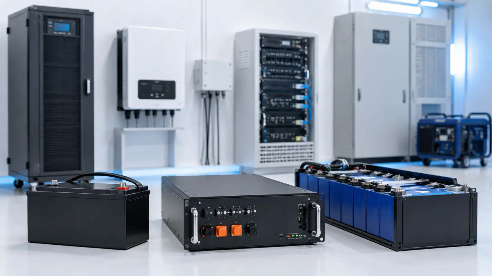
LiFePO4, or lithium iron phosphate, has become one of the most widely selected lithium-ion chemistries for backup power, solar systems, UPS equipment, industrial devices and energy storage. It is often chosen specifically for safety, thermal stability and long cycle life.
That reputation is largely deserved, but it has also created a dangerous simplification: the belief that an LFP battery cannot fail, cannot burn and does not require the same engineering discipline as other lithium-ion systems. In real OEM and energy-storage projects, most LiFePO4 safety problems do not begin inside the cathode material. They begin in the system: an incompatible series count and charger, imbalance hidden by the flat voltage curve, charging below freezing, an inverter connected without precharge, parallel modules joined at different states of charge, or prismatic cells constrained without a validated compression structure.
This guide is the LiFePO4 spoke of THOR Power’s battery safety series. It explains why LFP is generally more thermally stable, where the chemistry advantage ends, and which failure mechanisms dominate real LFP projects: incorrect voltage architecture, cell imbalance under an apparently normal pack voltage, low-temperature charging and lithium plating, prismatic-cell swelling and compression, parallel-pack equalization current, inverter inrush, contactor and precharge design, thermal runaway gas release and energy-storage compliance. It also shows what OEM buyers should verify before approving a custom LiFePO4 battery pack.
Teams evaluating an LFP project can begin with THOR Power’s custom lithium-ion and LiFePO4 battery pack solutions and then match the final pack to the real charger, inverter, load, enclosure and certification route.
Quick Answer for OEM Buyers
LiFePO4 is generally one of the more thermally stable commercial lithium-ion chemistries, but chemistry alone does not determine system safety. Safe performance depends on the exact cell model, correct series voltage and charger, group-level monitoring, cell balancing, low-temperature charge control, appropriately rated current interruption, prismatic-cell support or compression, thermal and gas management, installation conditions and controlled production changes.
A common procurement mistake is to treat an LFP pack as a direct replacement for a lead-acid battery or another “48 V” battery. The voltage window, charger behavior, state-of-charge estimation, fault current, terminal design and protection architecture can be different enough to cause repeated BMS shutdowns, inverter faults, premature aging or a safety event even when the nominal voltage and capacity appear compatible.
1. What Is a LiFePO4 Battery?
A LiFePO4 battery is a lithium-ion battery that uses lithium iron phosphate as the positive-electrode material. Commercial cells usually pair the LFP cathode with a graphite-based negative electrode and a non-aqueous electrolyte. The chemistry commonly has a nominal cell voltage around 3.2 V to 3.3 V, while the exact charge and discharge limits depend on the cell manufacturer and model.
LFP cells are manufactured in prismatic, cylindrical and pouch formats. Large prismatic cells are common in energy storage and industrial packs because fewer cells can create a high-capacity module. Cylindrical LFP cells may be selected for vibration resistance or modular assembly, while pouch LFP cells can support thinner custom shapes. The chemistry name does not define the mechanical requirements of each format.
LFP also has a relatively flat voltage plateau across much of its usable state-of-charge range. This is useful for stable equipment voltage, but it makes state-of-charge estimation and early imbalance detection more difficult when the design relies only on pack voltage.
2. Why LiFePO4 Is Generally More Thermally Stable
The olivine phosphate structure in LFP uses strong phosphorus-oxygen bonding and is generally less prone to release oxygen at elevated temperature than many layered nickel- or cobalt-rich cathode materials. This contributes to lower heat release and a higher resistance to self-accelerating cathode decomposition under comparable conditions. Modern reviews describe stability and safety as central advantages of LFP chemistry.
This advantage should be interpreted as a larger engineering margin, not immunity. The graphite anode, separator and organic electrolyte remain capable of exothermic reaction. A cell can still vent combustible gases, rupture or enter thermal runaway under overcharge, severe heat, internal short circuit or mechanical abuse. At pack and installation level, many cells can create high total energy even when each cell is comparatively stable.
Important Distinction
“More thermally stable” does not mean “cannot burn.” LFP chemistry can reduce the likelihood or severity of some failure pathways, but the final risk is determined by cell capacity, state of charge, abuse mechanism, enclosure, propagation path, released gases, ignition sources and system response.
3. Are LiFePO4 Batteries Safe?
Yes. LiFePO4 batteries can be used safely and are widely selected for applications where thermal stability, long cycle life and predictable power delivery are important. Their chemistry can offer a meaningful safety advantage compared with many high-nickel or cobalt-rich lithium-ion systems.
The correct safety statement, however, is conditional: an LFP cell must remain inside its approved electrical, thermal and mechanical operating region and be integrated into a battery system that detects and controls foreseeable faults. Sandia safety guidance emphasizes that lithium-ion batteries of any size and capacity can have thermal-runaway risk; risk management, rather than a claim of zero risk, is the safety objective.
An LFP battery can still fail through overcharge, external or internal short circuit, charging below the approved temperature, excessive current, mechanical damage, moisture, loose terminals, failed switching devices, unsuitable compression, propagation from an adjacent cell or exposure to an external fire.
4. How to Define a Safe LiFePO4 Battery Pack Specification
An LFP project should begin with the complete operating window of the product, not a generic request such as “12 V 100 Ah” or “48 V rack battery.” Series count, maximum charge voltage, inverter limits, current, charge temperature, communication, mechanical structure and compliance must be confirmed before the pack configuration is approved.
For non-standard voltage, housing, connector, communication or BMS requirements, request an early custom battery engineering review before the inverter, charger, enclosure or installation drawings are locked.
For LFP backup or energy-storage projects, compare energy storage battery model options early, then confirm series count, inverter voltage window, BMS, precharge, compression and compliance scope through an engineering review.
| Specification Item | What to Define | Why It Matters for Safety |
|---|---|---|
| Cell model and format | Approved manufacturer, cell model, prismatic/cylindrical/pouch format, capacity, current limits and temperature range | LFP chemistry does not make all cells interchangeable. Mechanical support, terminals, compression and safety evidence are model-specific. |
| Series count and voltage window | Nominal voltage, maximum charge voltage, discharge cutoff, inverter input range and number of series groups | A “48 V” LFP battery is often 15S or 16S. The full-charge voltage may exceed the limit of equipment designed around a different chemistry. |
| Capacity and parallel architecture | Runtime target, usable energy, parallel cells or modules, expected depth of discharge and redundancy | Parallel design changes current sharing, equalization current, available fault energy and isolation strategy. |
| Continuous, peak and inrush current | Average load, motor or inverter surge, pulse duration, regenerative current and DC-link capacitor inrush | The BMS, fuse, contactor, busbar and connector must survive real transients without nuisance trips or unsafe interruption. |
| Charging strategy | Charge voltage, current, termination, low-temperature cutoff, heating logic and solar/charger behavior | LFP must be charged with a model-appropriate profile. Low-temperature charging can produce lithium plating. |
| BMS and balancing | Per-cell sensing, over/under-voltage thresholds, passive or active balancing, temperature inputs, communications and fault recovery | The flat voltage curve can hide imbalance until the top or bottom of charge. Group-level monitoring is essential. |
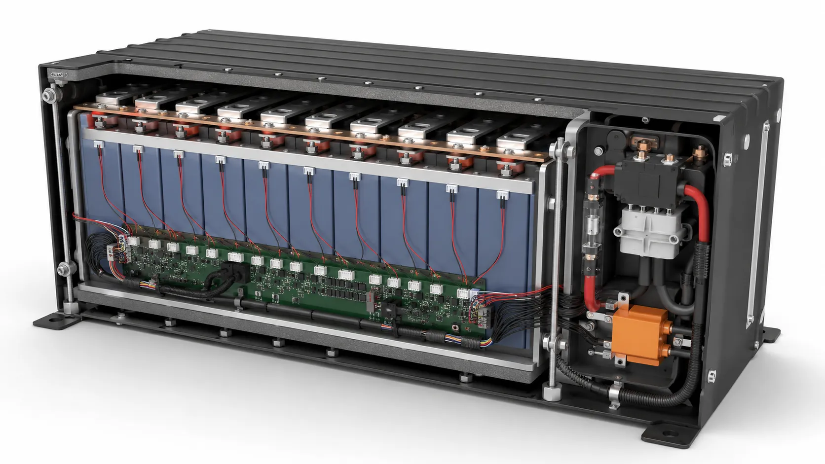
| Mechanical support and compression | Cell orientation, manufacturer compression guidance, end plates, pads, clearances, terminal loads and enclosure stiffness | Large prismatic cells change dimension during cycling. Too little or too much constraint can create mechanical and electrical problems. |
| Protection and switching | Fuse, contactor or MOSFET rating, precharge, manual disconnect, service isolation and fault-current coordination | Large LFP packs can deliver very high short-circuit current even when nominal voltage is moderate. |
| Thermal and gas management | Sensor map, heat paths, enclosure ventilation, vent direction, gas detection and separation from ignition sources | An LFP event may involve significant vent gas even if flame behavior is less severe than some other chemistries. |
| Documentation and installation | UN 38.3, IEC/UL scope, installation standard, report holder, BOM lock and field commissioning requirements | Cell or pack reports do not automatically cover the complete ESS, inverter or installation. |
Engineering Insight
Treat “LiFePO4” as the chemistry layer of the specification, not the complete design. The project is safe only when the cell, voltage architecture, charger, BMS, switching, mechanical support, enclosure, communications and installation are compatible as one system.
5. The Flat Voltage Curve: A Safety and Diagnostic Challenge
An LFP cell maintains a relatively stable voltage through much of its usable state-of-charge range. This is one reason LFP systems provide steady output, but it also means that a small voltage difference in the middle of the cycle may represent a significant difference in state of charge. Pack voltage alone can therefore be a weak indicator of cell balance.
Near the upper and lower ends of the state-of-charge range, cell voltage changes more rapidly. A weak, low-capacity or mismatched series group can reach the over-voltage threshold first during charging or the under-voltage threshold first during discharge. The BMS then shuts down even though the remaining groups still have available capacity.
Reliable designs use per-group voltage sensing, defined matching criteria, suitable balancing, calibrated state-of-charge estimation and end-of-charge behavior that gives the balancing system sufficient time without holding cells unnecessarily at the upper voltage limit.
Composite Engineering Case 1: A “48 V” Inverter That Could Not Accept a 16S LFP Pack
Project symptom: A product team specified a 48 V, 100 Ah LFP battery for an inverter with a maximum DC input of 56 V. The 16S pack was nominally 51.2 V but required a model-specific full-charge voltage near 58 V. The inverter reported over-voltage or the BMS disconnected near the top of charge.
Hidden engineering risk: The nominal voltage label hid an incompatibility between series count, charger voltage and inverter input range. Repeated hard BMS interruption also made charging behavior unstable.
Engineering response: Review the exact inverter voltage window, charger profile and BMS thresholds before selecting 15S or 16S. Use compatible equipment or redesign the voltage architecture instead of lowering the charge limit without validating capacity, balancing and cell-life consequences.
Buyer lesson: Never approve an LFP pack by the words “12 V,” “24 V” or “48 V” alone. Confirm nominal, maximum and minimum voltage at both battery and equipment level.
6. What Causes a LiFePO4 Battery to Fail or Enter Thermal Runaway?
Short answer: LiFePO4 is one of the more thermally stable lithium-ion chemistries, but it can still fail under abuse. The main causes are overcharging or an incorrect charge voltage, over-discharge, internal or external short circuits, mechanical damage and low-temperature charging that causes lithium plating. LFP typically has a higher thermal-runaway onset temperature and does not release oxygen the way nickel-based cells do, so failures tend to be less violent — but vent gas and heat are still hazards, so BMS protection and pack design remain essential.
1. Incorrect Series Count, Charger Voltage or Voltage Thresholds
The maximum charge voltage of a pack is the cell upper voltage multiplied by the number of series groups, subject to the limits approved for the exact cell. A charger designed for lead-acid batteries, another lithium-ion chemistry or a different series count may overcharge the LFP pack, terminate too early or repeatedly drive the BMS into hard cutoff. You can verify series-voltage and capacity math quickly with our battery calculators before locking the architecture.
BMS thresholds should provide abnormal-condition protection and coordinate with normal charger control. Using the BMS as the routine charge terminator can create cell stress, contactor cycling and inconsistent balancing. The charger, inverter and BMS must share a compatible voltage window.
2. Cell Imbalance Hidden by Normal Pack Voltage
In a multi-series LFP pack, total voltage can look acceptable while one cell is already near overcharge and another remains significantly lower. The flat plateau makes this particularly easy to miss if commissioning checks only total voltage.
Imbalance can originate from cell capacity differences, internal resistance, unequal self-discharge, temperature gradients, wiring resistance or replacement of one cell in an aged pack. Balancing is a corrective tool, not a substitute for cell matching and root-cause analysis.
Composite Engineering Case 2: A 12.8 V Pack That Shut Down at the Top of Every Charge
Project symptom: A four-series LFP pack showed normal total voltage during most of the cycle, but the BMS repeatedly stopped charging. Logged cell data showed one group reaching the over-voltage threshold while another remained hundreds of millivolts lower.
Hidden engineering risk: The total pack voltage concealed capacity and self-discharge differences. A small passive balancer could not correct the imbalance during the available charging time.
Engineering response: Verify cell capacity, internal resistance, self-discharge and connection resistance. Correct the abnormal group, review matching criteria and select a balancing strategy suitable for the pack size, duty cycle and maintenance interval.
Buyer lesson: A BMS trip is a symptom. Repeatedly resetting the pack without reviewing cell-level data can allow imbalance to worsen.
3. Low-Temperature Charging and Lithium Plating
LFP batteries can often discharge at low temperature within model-specific limits, but charging is more restrictive. At low temperature, lithium transport into the graphite anode slows. If current is too high, metallic lithium can plate on the anode rather than intercalate safely.
Lithium plating can reduce capacity, increase internal resistance and create deposits that contribute to internal-short risk. DOE research on fast charging identifies plating as a major limitation, with susceptibility affected by charge rate, temperature, cell design and state of health. The correct response may be to block charging, reduce current or preheat the pack according to validated cell data.
Composite Engineering Case 3: Outdoor Solar Backup Charged Below Freezing
Project symptom: A solar backup battery installed outdoors continued to accept charge at approximately -10 °C because the generic BMS used only a low discharge-temperature limit. The system initially worked, but later showed reduced capacity, growing imbalance and abnormal swelling.
Hidden engineering risk: Low-temperature charging created a lithium-plating risk that was not prevented by over-voltage or over-current protection. A single sensor near the BMS did not represent the coldest cells.
Engineering response: Use multiple sensors where necessary, implement a model-specific low-temperature charge cutoff, coordinate the solar charger with BMS status and add controlled heating or delayed charging if the application requires winter operation.
Buyer lesson: “The battery still charges” does not prove the charge is safe. Temperature-dependent current control must be part of the normal charging strategy.
4. Over-Discharge, Reversal and Unsafe Recovery
A weak LFP group can reach the under-voltage limit before the rest of the pack. Continued discharge, bypassing the BMS or repeatedly forcing recovery can damage the cell and increase imbalance. Severe over-discharge may also contribute to copper dissolution and internal failure during subsequent recharge.
Recovery logic should verify individual group voltage, temperature and abnormal self-discharge. Packs with a reversed group, swelling, leakage or repeated under-voltage shutdown require investigation rather than automatic return to service.
5. External Short Circuit, Loose Terminals and Excessive Current
Large LFP cells and modules can deliver very high fault current because of their low internal resistance and high capacity. A loose busbar, improperly torqued terminal, undersized conductor, reversed cable or conductive tool can create intense local heating, arcing or fire without requiring a cell thermal-runaway event.
The current path must be designed from the cell terminals through busbars, fuse, contactor, connectors and external cables. Torque specifications, locking methods, insulation covers, creepage and clearance, tool control and service procedures are important production and installation controls.
6. Inverter Inrush, Failed Precharge or Contactor Stress
Inverters and motor controllers often contain large DC-link capacitors. Connecting a battery directly can produce a high inrush current that causes connector arcing, BMS MOSFET trips, fuse stress or contactor welding. The normal operating current may be far lower than this connection transient.
Higher-energy LFP systems commonly use a precharge path that limits current while the downstream capacitance rises toward pack voltage, followed by controlled closure of the main contactor. Precharge resistance, power rating, timing, feedback and failure detection must match the actual inverter capacitance and system voltage. Defining these connection transients early is part of a structured custom battery project process.
Composite Engineering Case 4: A Rack Battery That Tripped Only When Connected to the Inverter
Project symptom: The 51.2 V battery passed charge-discharge tests on an electronic load but immediately triggered over-current protection when connected to the customer’s inverter. Repeated connection attempts created visible connector arcing.
Hidden engineering risk: The test plan did not include DC-link capacitor inrush. The BMS MOSFET and connector were being asked to interrupt a transient much higher than the steady load.
Engineering response: Measure inverter input capacitance and inrush, implement a controlled precharge circuit, coordinate contactor sequencing and verify fuse and connector ratings under connection and fault conditions.
Buyer lesson: A battery can pass steady-state testing and still be incompatible with the final equipment. Connection transients belong in the validation plan.
7. Parallel Modules at Different State of Charge
Connecting two LFP modules in parallel at different voltages can create a large equalization current limited mainly by internal resistance, cables and contact resistance. The current may bypass normal load assumptions and can damage connectors, fuses or switching devices.
Parallel systems need a defined connection sequence, acceptable voltage difference, branch fusing, current-sharing design, communication and isolation strategy. A pack should not be hot-plugged into an energized bus merely because the nominal voltage is the same.
Composite Engineering Case 5: Two Healthy Modules Damaged During Parallel Connection
Project symptom: A second 16S module was connected to a live DC bus after storage. Both modules were individually functional, but their states of charge differed. The connector sparked and one branch fuse opened.
Hidden engineering risk: The project treated the modules as identical voltage sources and did not control equalization current or verify voltage difference before connection.
Engineering response: Specify maximum connection-voltage difference, use branch protection and controlled precharge or contactor sequencing, and ensure the BMS or system controller manages parallel-module admission and current sharing.
Buyer lesson: Parallel redundancy adds system complexity. Each module needs isolation and connection rules, not only an individual BMS.
8. Internal Short Circuit and Latent Cell Defects
Internal shorts can originate from contamination, burrs, separator damage, electrode misalignment, mechanical deformation or aging. Incoming voltage and capacity checks cannot prove that every hidden defect is absent. High-quality cell sourcing, formation and aging records, self-discharge screening and traceability reduce risk but do not eliminate it.
The pack must therefore limit the consequence of an initiating cell failure through spacing, barriers, thermal paths, gas management, current interruption and system-level monitoring appropriate to the application.
9. Prismatic-Cell Swelling, Compression and Structural Error
Large prismatic LFP cells change thickness and generate force during normal cycling and aging. Research on commercial prismatic LFP/graphite cells confirms that swelling force varies with state of charge, cycling and mechanical conditions. The module must accommodate these forces without allowing excessive movement or applying uncontrolled pressure.
Too little support can allow cell movement, terminal fatigue and loss of thermal contact. Excessive or uneven compression can deform the case, load the separator or terminals and create localized stress. Compression values should come from the cell manufacturer’s guidance or validated module testing, not a generic rule copied from another cell size.
Composite Engineering Case 6: A Prismatic Pack That Fit the CAD Model but Distorted After Cycling
Project symptom: The enclosure was designed around the nominal cell dimensions with rigid side walls and no defined compression pads or expansion allowance. After cycling, the case bowed, busbars were loaded and terminal seals showed mechanical stress.
Hidden engineering risk: The design treated the cell as a dimensionally fixed block. Normal reversible expansion and long-term irreversible swelling were converted into uncontrolled structural force.
Engineering response: Use manufacturer-defined compression guidance, rigid end plates, compliant insulating pads, suitable clearances and a structure that distributes force uniformly while protecting terminals and vent areas. Validate at temperature and end-of-life conditions.
Buyer lesson: Mechanical integration is part of battery safety. “It fits” is not the same as “it remains safe through life.”
10. High Temperature, Poor Cooling and Uneven Cell Temperature
LFP cells generate heat during charge and discharge. High current, aging, connection resistance and poor airflow can create hot spots even when the chemistry is thermally stable. Temperature differences also accelerate imbalance because cell resistance and capacity vary with temperature.
Thermal validation should include the hottest ambient, full charge and discharge current, simultaneous operation of electronics, blocked airflow, enclosure heat and expected aging. Sensors should be placed near predicted hot cells, terminals, contactors and BMS power devices rather than only where wiring is convenient.
11. Moisture, Condensation and Installation Faults
Stationary and outdoor LFP systems may experience condensation, dust, insects, corrosion or cable damage. Moisture can create leakage paths on the BMS, reduce insulation resistance or corrode terminals. Installation errors can include reversed polarity, inadequate cable protection, poor grounding, blocked ventilation and placement near heat or ignition sources.
The battery enclosure, connectors, sealing, drainage, insulation monitoring where applicable, installation clearances and maintenance instructions must reflect the actual environment. Cell-level safety cannot compensate for an unsafe field installation.
12. Aging, Second-Life Cells and Uncontrolled Substitution
LFP is known for long cycle life, but aging still changes capacity, internal resistance, self-discharge and swelling behavior. A pack may remain operational while becoming less balanced or running hotter under the same load. Sandia research emphasizes that safety effects depend on aging history and the metric being evaluated.
Second-life or mixed-history cells require an application-specific qualification process. Replacing one cell in an aged welded or bolted series string can create mismatch. In production, substituting a cell, BMS component, contactor, busbar or insulation material without re-evaluation can invalidate previous tests even if the external pack appears unchanged.
7. How Thermal Runaway Develops in a LiFePO4 Cell
Thermal runaway is a self-accelerating condition in which internal heat generation exceeds heat dissipation. The trigger can be overcharge, external heating, internal short circuit, mechanical damage or another cell failure. LFP often requires more severe abuse to reach runaway than many layered-oxide chemistries, but once the internal reactions become self-sustaining, removing the external load may not stop the process.
Large-capacity LFP studies show that trigger method matters. Research comparing overcharge and overheating in 86 Ah LFP cells found differences in vent timing, gas behavior and thermal-runaway development. The practical implication is that one test method cannot represent every field fault, and system design should consider electrical, thermal and mechanical initiators.
State of charge remains important because it affects the stored energy and reaction potential. A pack used for backup may spend long periods near high state of charge. Charge-voltage strategy, thermal environment, early warning and maintenance therefore matter even when the battery is rarely cycled.
Important Limitation
Do not publish or program a universal “LiFePO4 thermal-runaway temperature.” Onset, venting, ignition and peak behavior vary with cell model, capacity, state of charge, age, trigger, enclosure and test method. Use model-specific data and system-level validation.
8. Vent Gas Can Be a Serious Hazard Even Without Sustained Flame
An LFP cell can vent a substantial quantity of gas before or during thermal runaway. Experimental studies of high-capacity LFP cells report combustible and toxic gas mixtures whose composition and volume depend on cell design and abuse condition. Gas can accumulate inside cabinets, rooms or containers and later ignite when it reaches an electrical arc, hot surface or other ignition source.
This creates an important misconception: observing limited flame at the cell does not prove the installation has low fire or explosion risk. Venting, gas dispersion, enclosure volume, ventilation, detection, pressure relief and separation from ignition sources must be considered at system and installation level.
For stationary energy storage, large-scale fire and propagation testing is used to evaluate how a representative system behaves when thermal runaway occurs. UL 9540A is a test method for assessing thermal-runaway fire propagation and associated hazards in battery energy storage systems.
Worried about vent gas or cell failure in your LFP pack? Get a free safety review.
Talk to a Battery Engineer9. What an LFP BMS Can and Cannot Do
| BMS Function | What It Can Help Control | Important Limitation |
|---|---|---|
| Per-cell voltage monitoring | Detect overcharge, over-discharge and imbalance in each series group | Cannot identify every internal defect or correct a cell with severe capacity loss or self-discharge. |
| Current monitoring and interruption | Limit overload and short-circuit duration | MOSFETs, contactors, shunts and fuses must be rated for real DC fault energy and interruption conditions. |
| Temperature monitoring | Block low-temperature charging and stop operation outside validated limits | Sensors only represent their locations; poor placement can miss cold or hot cells and terminal hot spots. |
| Balancing | Reduce voltage divergence between series groups | Cannot replace cell matching, fix a damaged group or compensate for inadequate charging time. |
| SOC/SOH estimation | Support runtime, reserve energy, diagnostics and maintenance | The flat LFP voltage curve requires accurate current integration, calibration and temperature-aware algorithms. |
| Contactor and precharge control | Sequence connection to high-capacitance loads and isolate faults | A poor sequence, welded contactor or failed precharge path can defeat the intended protection. |
| Communications and event logging | Coordinate inverter limits, alarms, service and fault analysis | Communication loss, incompatible protocols or unsafe automatic recovery can create repeated faults. |
The BMS should be one layer in a defense-in-depth architecture that includes correct cell selection, charger control, fuse coordination, contactors or current interruption, sensor placement, mechanical support, thermal and gas management, enclosure protection, installation rules and production traceability. For custom protection thresholds, precharge design, NTC configuration, cable and communication requirements, review connector, wire and PCM/BMS customization as part of the complete architecture.
10. Passive vs. Active Balancing: Which Is Safer?
Passive balancing removes a small amount of energy from higher-voltage groups, usually through resistors. It is simple and common, but its correction current may be limited. Active balancing transfers energy between groups and can correct larger differences more efficiently, but adds cost, circuitry and control complexity.
Neither method is automatically safer. The correct choice depends on cell capacity, expected mismatch, charge time, standby behavior, service interval and failure analysis. A 100 Ah rack battery with a very small passive balance current may need many hours near the top of charge to correct a meaningful capacity difference. Holding every cell at high voltage solely to provide balance time can create another tradeoff.
| Project Condition | Possible Balancing Direction | Engineering Check |
|---|---|---|
| Small, well-matched pack with regular full charge | Passive balancing may be sufficient when current and available time are validated | Verify that the balance current can correct expected drift before protection thresholds are reached. |
| Large-capacity pack with limited time near top of charge | Higher passive current or active balancing may be considered | Review heat from passive resistors, active-balancer failure modes and communication with the main BMS. |
| Parallel modules in a serviceable system | Module-level balancing does not replace branch current control and admission logic | Control voltage difference before connection and provide branch isolation. |
| A pack with repeated large imbalance | Do not treat balancing as the only remedy | Investigate capacity, self-discharge, temperature, loose connections and cell damage. |
11. Prismatic LiFePO4 Cell Compression and Module Design
Many high-capacity LFP packs use prismatic cells because they reduce interconnection count and package energy efficiently. These cells are not rigid blocks. Electrodes and casing change dimension with state of charge, temperature and aging, generating swelling force against the module structure.
The module should maintain alignment and electrical contact while distributing pressure uniformly and protecting vent areas and terminals. End plates, tie rods or frames, insulating barriers and compliant pads may be used, but the design must be validated for the exact cell. A compression method intended for one manufacturer, capacity or case design should not be assumed appropriate for another.
The structure must also allow assembly tolerances and end-of-life growth. Busbars should tolerate relative movement without excessive terminal load. Temperature sensors and service access must remain effective when the module is under compression. Enclosure walls should not be used as an uncontrolled compression device unless the enclosure has been specifically designed and validated for that role.
12. How Modern LiFePO4 Battery Systems Reduce Risk
Traceable Cell Selection and Locked Supply Chain
Use the exact approved LFP cell model from a traceable source. Confirm approval data, dimensions, terminal design, compression guidance, current limits, temperature range and applicable reports. Establish change control so a supplier cannot replace the cell with a visually similar alternative without approval.
Correct Series Count and Charger Coordination
Define nominal, full-charge and cutoff voltage before selecting the inverter, charger and BMS. Validate charge current, termination, solar or generator behavior, operation while charging and recovery after power loss.
Cell Matching, Monitoring and Balancing
Measure open-circuit voltage, internal resistance and capacity according to project risk. Monitor every series group, select a balancing strategy that matches capacity and duty cycle, and record cell-lot and pack serial traceability.
Low-Temperature Charge Protection
Place sensors where they represent the coldest cells, not only the BMS. Block or reduce charging below model-specific temperatures and coordinate heaters, solar chargers and inverters so the system cannot bypass the policy.
Fuse, Contactor and Precharge Coordination
Select DC-rated fuses, contactors, MOSFETs, precharge components and manual disconnects for normal current, inrush and prospective fault current. Verify interruption behavior and fault recovery in the final system.
Mechanical Compression and Terminal Protection
Use a validated module structure with insulated end plates, compliant pads, controlled torque, protected busbars and strain relief. Accommodate cycling and aging expansion while keeping vents and service points clear.
Thermal and Vent-Gas Management
Map cell and connection temperatures under worst-case load and ambient conditions. Provide appropriate heat paths, gas detection or ventilation, pressure relief and separation from ignition sources according to the application.
System and Installation Validation
Test the battery with the real inverter, charger, loads, communications and enclosure. For stationary systems, review installation clearances, fire protection, emergency disconnect, commissioning and maintenance requirements.
Manufacturing Traceability and Field Feedback
Record cell lots, BMS firmware, contactor and fuse versions, torque results, insulation tests, final electrical checks and pack serial numbers. Use field events to update risk analysis and prevent unapproved substitutions. A controlled battery pack production process helps keep cell matching, busbar assembly, torque, BMS testing, insulation, aging and final inspection consistent from approved samples to mass production.
13. LiFePO4 Battery Safety Review: Failure Mode and Design Response
| Failure Mode | Engineering Response | Evidence an OEM Buyer Can Request |
|---|---|---|
| Wrong series count or charger | Coordinate cell upper voltage, series count, charger and equipment input window | Voltage architecture, charger curve, BMS thresholds and compatibility test |
| Cell imbalance | Group-level monitoring, matching, balancing and root-cause investigation | Cell logs, capacity/IR data, balance-current calculation and self-discharge results |
| Low-temperature charging | Temperature-dependent charge cutoff, derating or controlled heating | Sensor map, charge-temperature policy and cold-charge test |
| Short circuit or loose terminal | DC-rated protection, correct conductor sizing, torque control and insulated service access | Fault-current study, fuse/contactor specification, torque record and thermal test |
| Inverter inrush | Precharge path, controlled contactor sequence and feedback | Inrush waveform, precharge timing, resistor rating and fault-recovery test |
| Parallel-module equalization | Voltage-difference limit, branch fuse, admission logic and isolation | Connection procedure, branch-current data and controller sequence |
| Prismatic swelling or stress | Manufacturer-based compression, end plates, compliant pads and expansion allowance | Mechanical drawing, preload/compression validation and end-of-life clearance review |
| Thermal hot spot | Sensor placement, heat paths, derating and worst-case thermal validation | Thermal map, temperature-rise report and sensor-location drawing |
| Vent gas and propagation | Vent path, detection, enclosure strategy and system-level fire/propagation evaluation | Risk assessment, gas or UL 9540A evidence where required |
| Unauthorized substitution | BOM lock, revision control and revalidation before change | Approved parts list, deviation record, revision history and test impact review |
14. Application-Specific LiFePO4 Safety Priorities
Residential and Commercial Energy Storage
These systems combine high total energy, long high-state-of-charge periods, inverter electronics, installation constraints and potential indoor placement. Safety priorities include certified system architecture, compatible inverter communications, branch isolation, emergency disconnect, thermal and gas management, installation clearances, commissioning and maintenance.
For installation-focused risks and system-level incident lessons, continue to our home energy storage battery safety guide.
UPS, Telecom and Long-Standby Backup
Backup power batteries may remain at high state of charge for months and are expected to respond immediately during an outage. Float-like charging strategies copied from lead-acid systems may be inappropriate. Long-term charger behavior, communication, self-test, temperature, calendar aging and service replacement criteria are central safety issues.
Solar and Outdoor Systems
Outdoor systems face low-temperature charging, high enclosure temperature, condensation, variable solar current and long unattended operation. The battery must communicate or otherwise coordinate with the charger so temperature and voltage limits cannot be bypassed when sunlight returns after a cold night.
Industrial Equipment and Motive Auxiliary Power
Industrial packs may experience vibration, high-current loads, regenerative energy, frequent connection and service. Safety priorities include robust terminals, precharge, contactors, communication, mechanical restraint, thermal validation and clear maintenance isolation.
15. Which Standards Apply to LiFePO4 Cells, Packs and Energy Storage Systems?
The applicable standards depend on whether the product is portable, industrial, stationary, motive auxiliary or a complete energy storage system. LiFePO4 is still a lithium-ion chemistry, so standards are selected by product and application scope rather than by the chemistry name alone.
IEC 62619:2022 specifies safety requirements and tests for secondary lithium cells and batteries used in industrial applications, including stationary applications. IEC 62485-5:2020 addresses safety aspects associated with installation, use, inspection, maintenance and disposal of stationary lithium-ion batteries. IEC 62620:2014+A1:2023 addresses performance marking and tests for industrial secondary lithium cells and batteries.
UN Manual of Tests and Criteria, Sub-section 38.3, addresses transport testing for lithium cells and batteries. In North America, UL 1973 is used for batteries in stationary and motive auxiliary power applications, UL 9540 addresses complete energy storage systems and UL 9540A evaluates thermal-runaway fire propagation and related hazards. NFPA 855 provides minimum installation requirements for stationary energy storage systems.
| Reference | Primary Purpose | Buyer Reminder |
|---|---|---|
| IEC 62619 | Industrial secondary lithium cells and batteries, including stationary applications | Confirm exact model, configuration, report holder and edition. |
| IEC 62485-5 | Installation, use, inspection, maintenance and disposal of stationary lithium-ion batteries | A pack test does not replace installation safety requirements. |
| IEC 62620 | Performance marking and tests for industrial lithium cells and batteries | Performance evidence is different from safety certification. |
| UN 38.3 | Transport testing for lithium cells and batteries | Supports shipment compliance but is not an end-product or installation safety approval. |
| UL 1973 | Batteries for stationary and motive auxiliary power applications | Applies at battery/module/system level according to product scope. |
| UL 9540 | Energy storage systems and equipment | Evaluates the complete ESS rather than only the cell or battery pack. |
| UL 9540A | Test method for thermal-runaway fire propagation in battery energy storage systems | Provides data used to evaluate fire, gas, propagation and installation mitigation. |
| NFPA 855 | Installation of stationary energy storage systems | Addresses siting, separation, fire protection and other installation requirements. |
Buyers can review THOR Power’s battery certificates and compliance documents while confirming that every report matches the exact cell, BMS, series count, enclosure and final product scope.
16. Common OEM Mistakes in LiFePO4 Battery Projects
Assuming Every “48 V” System Is Compatible
A 15S or 16S LFP battery, a lead-acid charger and an inverter marketed as 48 V can have incompatible maximum and minimum voltage limits.
Using Pack Voltage Instead of Cell-Level Data
The flat LFP voltage curve can hide imbalance. Commissioning and field diagnostics must inspect every series group, not only total voltage.
Allowing Charge Below Freezing Without Model-Specific Validation
Over-voltage protection does not prevent lithium plating. Low-temperature charge control belongs in the charger-BMS system.
Selecting a BMS Only by Current Rating
A “100 A BMS” label does not define short-circuit interruption, MOSFET heat, contactor logic, precharge, balancing, temperature policy or communications.
Using the Enclosure as an Uncontrolled Cell Clamp
Prismatic cells need model-specific support or compression. A tight metal box with no compliant structure can transfer swelling force into terminals and seals.
Connecting Parallel Modules Without Voltage Matching
Equalization current can exceed normal load current. Parallel admission needs voltage checks, branch protection and controlled switching.
Approving a Sample Without Locking Components
Changing the cell, BMS, fuse, contactor, busbar, foam or firmware can change voltage, heat, fault response and report scope.
Using a Cell or Pack Certificate as Proof of Complete ESS Safety
A stationary installation also involves inverter, enclosure, fire and gas behavior, site conditions, disconnects and installation standards.
17. How OEM Buyers Should Evaluate a LiFePO4 Battery Pack Supplier
For broader lithium-ion failure mechanisms and general safety-layer logic, use the lithium-ion battery safety guide as the hub article; this page focuses on LFP-specific pack and system risks.
A supplier should be evaluated by engineering evidence and production control, not only by claimed cycle life, capacity or the word “safe.” Buyers should ask for:
| Evaluation Area | LFP-Specific Evidence to Request |
|---|---|
| Voltage architecture | 15S/16S decision, full-charge voltage, cutoff voltage, charger curve and inverter compatibility test. |
| BMS and balancing | Cell-level logs, balance-current calculation, SOC/SOH strategy, NTC map, fault thresholds and recovery logic. |
| Precharge and current interruption | DC-rated fuse/contactors, precharge timing, inrush waveform, branch protection and fault-recovery test. |
| Mechanical module design | Compression/support drawing, terminal torque, busbar movement allowance, insulation and end-of-life expansion review. |
| Thermal and gas management | Thermal map, sensor placement, ventilation or gas strategy and installation assumptions. |
| Traceability and change control | Cell lot mapping, BMS firmware revision, final test records and formal approval for substitutions. |
18. What to Send Your Battery Supplier Before Sample Development
A supplier can recommend a safer LFP system when the first inquiry includes the actual electrical, mechanical and installation context. The following inputs prevent a quote from being based only on voltage and capacity:
| LFP Project Input | Why It Matters | What Can Go Wrong If Missing |
|---|---|---|
| Inverter voltage window | Confirms whether 15S, 16S or another architecture is compatible with maximum and minimum equipment limits. | A nominal 48 V pack can over-voltage the inverter or trip the BMS at the top of charge. |
| DC-link capacitance and inrush | Defines whether precharge, contactor sequencing or MOSFET protection must be added. | The pack may pass load testing but trip or arc when connected to the real inverter. |
| Low-temperature charging environment | Determines sensor placement, charge cutoff, derating or heater logic. | The system may charge below freezing and create lithium-plating risk. |
| Parallel-module plan | Defines voltage-matching limits, branch protection, admission logic and isolation. | Modules at different SOC can create damaging equalization current. |
| Prismatic-cell compression guidance | Controls end plates, pads, clearances, terminal stress and end-of-life expansion allowance. | A pack that fits the CAD model may distort after cycling or load terminals mechanically. |
| Installation environment | Captures indoor/outdoor location, condensation, ventilation, fire separation and service access. | A safe cell-level pack may still be unsafe in the final cabinet, room or outdoor enclosure. |
| Compliance target | Determines whether IEC 62619, IEC 62485-5, UL 1973, UL 9540, UL 9540A, NFPA 855 or transport documents apply. | A cell or pack report may not cover the complete system or installation. |
| Production control requirements | Locks cell model, BMS firmware, contactor, fuse, busbar, compression parts and final tests. | A visually similar substitution can change voltage behavior, fault response, thermal risk or report scope. |
Teams with drawings, an inverter specification or an existing system can request a battery solution and attach the voltage window, load profile, installation environment and compliance target.
19. How THOR Power Supports Safer Custom LiFePO4 Battery Projects
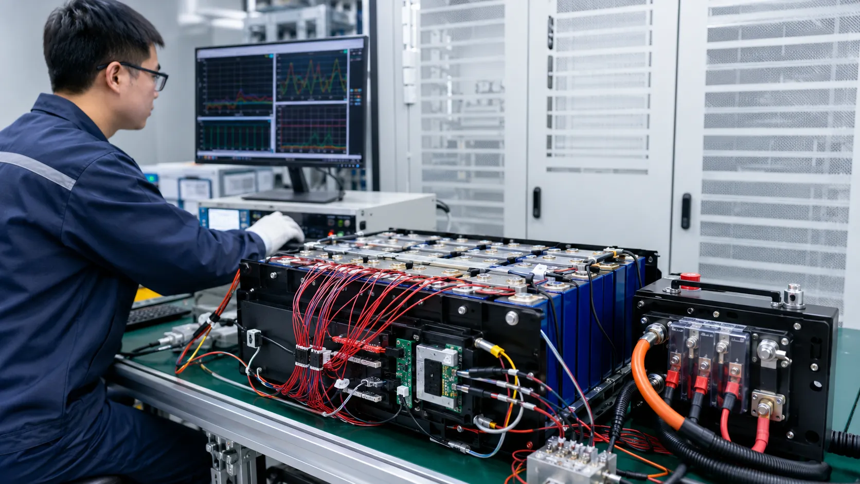
THOR Power supports custom LiFePO4 battery packs for UPS, telecom backup, solar systems, industrial equipment, outdoor backup power and selected residential or commercial energy-storage projects. The engineering review begins with the application and complete voltage-current environment rather than a catalog capacity.
The project workflow can include requirement review, cell and series-count selection, BMS and balancing design, fuse/contactor/precharge coordination, connector and cable confirmation, prismatic-module structure, thermal and gas review, sample build, inverter or final-device testing, documentation planning and mass-production control.
For approved projects, controlled items may include the cell model and lot rules, BMS hardware and firmware, balance current, MOSFET or contactor, fuse, precharge resistor, NTC values and locations, busbar, terminal torque, insulation, compression pads, end plates, enclosure interface, communications, labels, packaging and final test items.
20. When to Involve THOR Power
The best time to involve THOR Power is before the inverter, charger, enclosure, busbars and certification route are fully locked. Early review gives the project team more freedom to select 15S or 16S architecture, define low-temperature charging, add precharge, design cell compression and align the battery with installation requirements.
If the project already has a prototype, send the inverter and charger specifications, cell-level BMS logs, current profile, enclosure drawing, temperature range and target market. THOR Power can review whether the existing direction is suitable or whether the voltage architecture, balancing, switching or module structure should be revised.
Planning a Custom LiFePO4 Battery Pack?
Send us your inverter specifications, load profile, installation environment and compliance target. Our engineers will recommend the right cell, series architecture, BMS and precharge design – with samples, UN38.3/MSDS support, and stable mass production.
Talk to a Battery EngineerKey Takeaways
- LiFePO4 is generally more thermally stable than many layered-oxide lithium-ion chemistries, but it is not fireproof or misuse-proof.
- “12 V,” “24 V” and “48 V” labels do not define full-charge voltage or equipment compatibility. Confirm series count and the complete voltage window.
- The flat LFP voltage curve makes cell-level monitoring, SOC estimation and balancing especially important.
- Low-temperature charging can cause lithium plating even when discharge at the same temperature is allowed.
- Large LFP cells and modules can deliver high fault current; fuses, contactors, busbars, cables and disconnects must be DC-rated and coordinated.
- Inverter inrush and parallel-module equalization current can exceed normal operating current and require controlled precharge or switching.
- Prismatic cells need model-specific support or compression, uniform force distribution and allowance for cycling and aging expansion.
- LFP thermal runaway can release combustible and toxic gases even when visible flame is limited.
- IEC 62619, IEC 62485-5, UL 1973, UL 9540, UL 9540A, NFPA 855 and UN 38.3 serve different purposes and must match the final product and installation.
- The safest custom LFP battery is designed around the real inverter, charger, load, enclosure, environment, service model and production controls.
Conclusion
LiFePO4 has earned its position as a preferred chemistry for many backup-power, industrial and energy-storage projects because it can combine long cycle life with strong thermal stability. That advantage is real, but it should be used to build a safer system rather than support an absolute claim that the battery cannot fail.
The most important LFP risks are often system-integration problems: a 16S pack connected to incompatible 48 V equipment, low-temperature charging allowed by a generic BMS, imbalance hidden by the flat voltage curve, prismatic cells constrained without a validated compression structure, inverter inrush without precharge or parallel modules connected at different states of charge.
OEM buyers should evaluate the complete architecture. The cell model, charger, BMS, balancing, current interruption, mechanical structure, thermal and gas management, inverter behavior, installation and mass-production controls must work together. Cell-level stability cannot compensate for an unsafe voltage window, weak connection or unsuitable enclosure.
THOR Power supports custom LiFePO4 battery development with application review, cell and voltage selection, PCM/BMS and balancing integration, connector and structure customization, sample testing, compliance planning and production quality control. Review our in-stock energy storage battery models when you are ready to move from planning to a concrete platform.
FAQ: LiFePO4 Battery Safety
Are LiFePO4 batteries safe?
Yes, when authentic cells are operated within model-specific voltage, current, temperature and mechanical limits and integrated with suitable BMS, charger, fusing, switching, thermal management and installation controls. LFP generally offers strong thermal stability but is not risk-free.
Can LiFePO4 batteries catch fire or explode?
A severely abused or defective LFP cell can vent, ignite or rupture. Overcharge, internal short circuit, external heating, mechanical damage and propagation from another cell can trigger failure. Vent gases can also create fire or explosion hazards if they accumulate and meet an ignition source.
What makes the LFP cathode structure more thermally stable?
The phosphate cathode structure is generally more thermally stable and less prone to oxygen release than many layered nickel- or cobalt-rich cathodes. This can reduce heat release and increase abuse tolerance, but pack design and operating conditions remain decisive.
Does a LiFePO4 battery need a BMS?
Most rechargeable multi-cell LFP packs require a BMS appropriate to the series-parallel configuration and application. Typical functions include per-cell over/under-voltage protection, current and temperature protection, balancing, SOC estimation, communications and contactor or MOSFET control.
What is the full-charge voltage of a 16S LiFePO4 battery?
The theoretical value depends on the approved upper voltage of the exact cell multiplied by 16. Many systems are designed around a maximum near 58.4 V, but the correct charger and BMS limits must come from the selected cell and application. Do not use a generic value without validation.
Is a 16S LiFePO4 battery compatible with every 48 V inverter?
No. Some 48 V equipment has a maximum input below the full-charge voltage of a 16S LFP pack. Confirm the inverter input range, charger, low-voltage cutoff and BMS thresholds before choosing 15S or 16S.
Can LiFePO4 batteries be charged below 0 °C?
Only if the exact cell manufacturer permits it at a defined current and the system has been validated. Many LFP systems block charging below freezing because low-temperature charging can cause lithium plating. Some applications use controlled heating before charging.
What is the difference between passive and active balancing?
Passive balancing dissipates energy from higher-voltage groups, while active balancing transfers energy between groups. The better choice depends on cell capacity, expected drift, charge time, thermal design and maintenance needs. Neither method repairs a damaged or mismatched cell.
Do prismatic LiFePO4 cells need compression?
Many large prismatic cells require controlled mechanical support or compression according to manufacturer guidance. The correct preload and structure are cell-specific. Too little support or excessive, uneven pressure can both create problems.
Is UN 38.3 the same as IEC 62619 or UL 1973?
No. UN 38.3 addresses transport testing. IEC 62619 covers industrial secondary lithium cells and batteries. UL 1973 addresses batteries for stationary and motive auxiliary applications. Complete energy storage systems and installations may require UL 9540, UL 9540A, NFPA 855 or other standards.
References
- Lu et al. Status and Prospects of Lithium Iron Phosphate Manufacturing in the Lithium Battery Industry.
- Sandia National Laboratories. Thermal Runaway Risk Assessment of Li-Ion Batteries.
- DOE/OSTI. Developing Extreme Fast Charge Battery Protocols.
- Li et al., Journal of Power Sources (2024). Insights into the Swelling Force in Commercial LiFePO4/Graphite Prismatic Cells.
- Sandia National Laboratories. Impact of Aging on the Safety of Lithium-Ion Batteries.
- Jia et al., Journal of Energy Storage (2023). Comparative Investigation of Thermal Runaway and Gas Venting of LiFePO4 Batteries Under Overcharging and Overheating.
- Qian et al., Energies (2023). Thermal Runaway Vent Gases from High-Capacity Energy Storage LiFePO4 Batteries.
- NREL. Review: Thermal Safety Management in Li-Ion Batteries.
- International Electrotechnical Commission. IEC 62619:2022.
- International Electrotechnical Commission. IEC 62485-5:2020.
- International Electrotechnical Commission. IEC 62620:2014+A1:2023.
- UNECE. UN Manual of Tests and Criteria, Revision 8 — Sub-section 38.3.
- UL Solutions. Battery Module and Pack Testing for Manufacturers.
- UL Solutions. UL 9540A Test Method for Battery Energy Storage Systems.
- National Fire Protection Association. NFPA 855: Standard for the Installation of Stationary Energy Storage Systems.
- NREL. Effects of Trigger Method on Fire Propagation During Li-Ion Battery Thermal Runaway.


Dr. Maximilian Weber is THOR Power's Chief Scientist and a senior expert in lithium battery technology. His technical review focuses on battery safety, performance optimization, energy density and custom battery solution development.
Last technical review: July 2026

Victor Xiong holds a Master's degree from The Chinese University of Hong Kong, Shenzhen. He leads THOR Power's OEM Division and focuses on custom battery solutions for global device brands, product developers and industrial customers.