
18650 Battery Safety Engineering Guide: Cell Selection, Pack Design, BMS Protection and OEM Risk Control

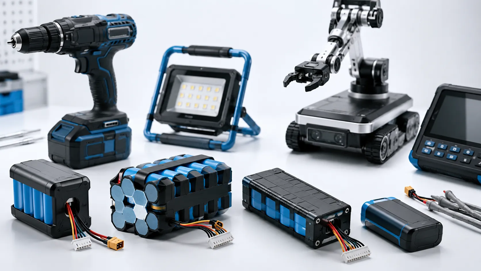
18650 lithium-ion cells have powered laptops, power tools, portable lighting, robotics, security equipment, medical devices and industrial battery packs for decades. Their cylindrical steel construction, mature supply chain and ability to support either high energy or high power make them one of the most established rechargeable cell formats in the market.
However, the familiarity of the format can create a dangerous misunderstanding. The number 18650 describes a physical cell size; it does not guarantee chemistry, capacity, discharge capability, manufacturing quality or safety performance. Two cells with the same dimensions can have very different current limits, charging requirements, internal protective devices and thermal behavior.
For OEM and ODM projects, 18650 battery safety therefore depends on far more than selecting a well-known cylindrical cell. A reliable battery pack must combine authentic and application-matched cells with consistent grading, validated interconnections, electrical protection, temperature monitoring, mechanical insulation, controlled venting paths, thermal propagation mitigation and disciplined production control.
This guide explains the most important 18650 safety risks, including loose and counterfeit cells, torn insulation wraps, overcharge, short circuits, poor cell matching, unsafe welding and cell-to-cell thermal propagation. It also shows how modern pack engineering reduces those risks and what buyers should verify before approving a custom 18650 battery pack.
Before selecting a pack configuration, buyers can compare available 18650 / 21700 cell model options and then match cell choice with voltage, capacity, current and production requirements.
Quick Answer for OEM Buyers
18650 safety is not decided by the cell format alone. It is decided by the exact cell model, series-parallel configuration, BMS logic, conductor design, thermal path, enclosure, charger behavior, documentation scope and mass-production change control.
For product developers and purchasing teams, the real risk is often hidden in early assumptions. A pack may look correct by voltage and capacity while the selected cell cannot support peak current, the BMS threshold is mismatched, the nickel strip overheats, or the final certification report does not cover the production configuration.
1. What Is an 18650 Battery?
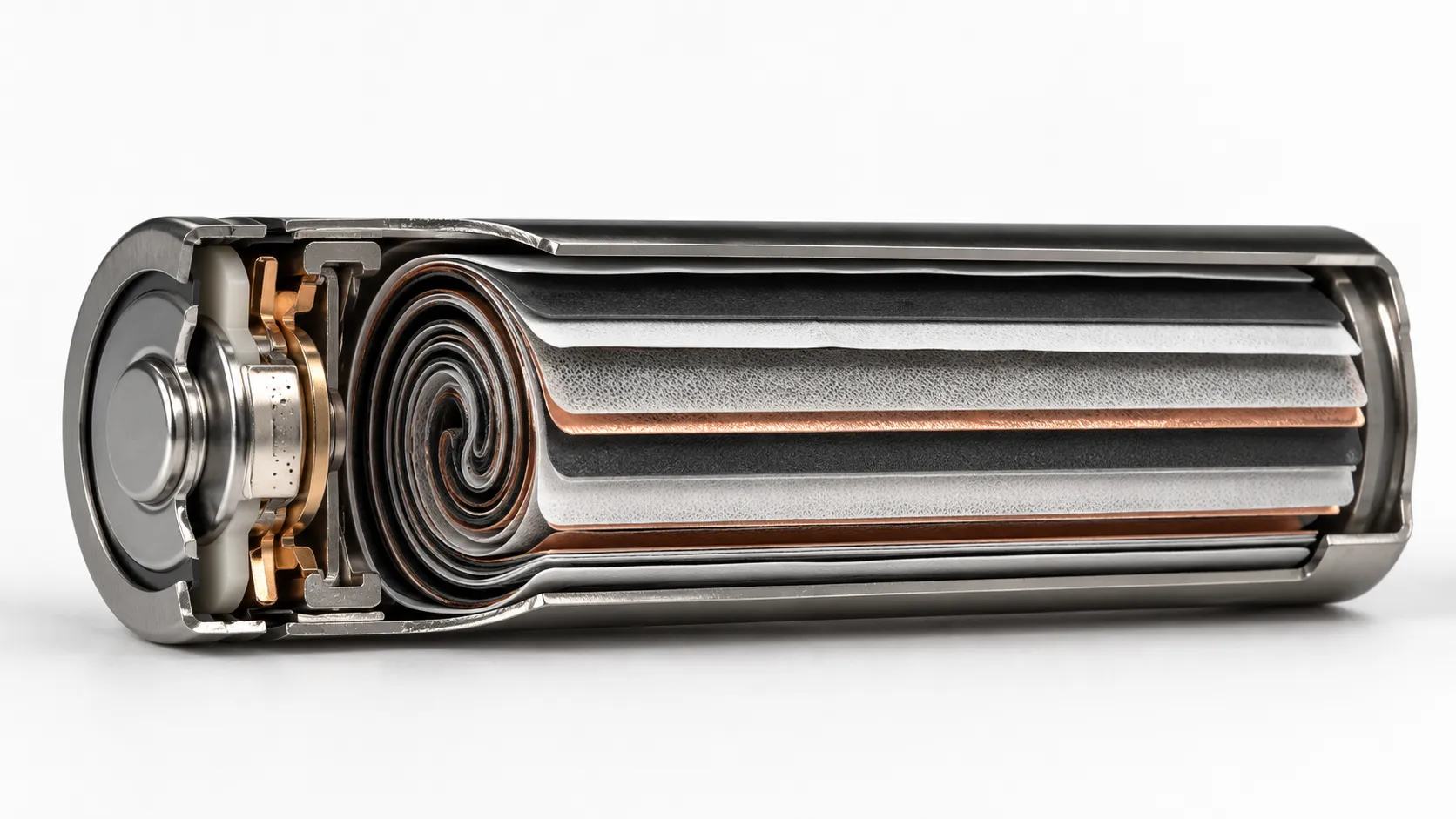
An 18650 battery is a cylindrical rechargeable cell format approximately 18 mm in diameter and 65 mm in length. The cell typically uses a steel can, a wound internal electrode assembly often called a jelly roll, a separator, electrolyte and a sealed positive-terminal cap assembly. Manufacturer tolerances can make the finished dimensions slightly larger than the nominal format.
The format does not define one chemistry. Commercial 18650 cells may use different lithium-ion cathode and anode systems, and each model has its own nominal voltage, upper charging voltage, minimum discharge voltage, current capability and temperature range. A model designed for long runtime may have a lower continuous discharge rating than a high-power model intended for tools or robotics.
This distinction matters because an attractive capacity number does not prove that a cell can safely support the real load. Selecting a high-energy cell for a high-pulse-current application can create excessive voltage drop and heat. Selecting a high-power cell for a low-current product may sacrifice capacity or increase cost without improving the final product.
2. How to Define a Safe 18650 / 21700 Battery Pack Specification
A safe battery-pack discussion should begin with the operating requirements of the product, not with a generic request for a voltage and capacity. The specification must connect electrical demand, mechanical limits, thermal conditions and documentation needs before the sample is built.
This table should be treated as a project-start checklist. If one item is unknown, the supplier may still quote a pack, but the quotation will carry more technical risk. If your team needs a non-standard voltage, connector, wire length, casing or BMS layout, start with a custom battery engineering review before the enclosure and charger are locked.
| Specification Item | What to Define | Why It Matters for Safety |
|---|---|---|
| Voltage and series count | Nominal voltage, maximum charge voltage, cutoff voltage and number of series groups | Series count determines pack voltage and whether group-level monitoring and balancing are required. |
| Parallel count and capacity | Target runtime, cell capacity, number of cells in parallel and usable capacity window | Parallel design affects current sharing, fault current and how much energy is available if one cell fails. |
| Current profile | Standby, average, continuous, peak current, pulse duration and duty cycle | Average current alone can hide motor-start, radio-transmission or stall conditions that create heat. |
| Cell model and chemistry | Approved manufacturer, model, chemistry, discharge rating, charge profile and temperature limits | The 18650 or 21700 size does not define performance or internal protection features. |
| BMS / PCM / fuse strategy | Protection thresholds, MOSFET rating, balance function, NTC inputs and short-circuit behavior | Protection must match the real pack configuration and load, not only the nominal voltage. |
| Mechanical and thermal design | Cell holder, insulation, vent path, spacing, heat sources and enclosure material | Pack layout controls short-circuit risk, hot spots and propagation consequences. |
| Documentation and change control | UN 38.3, SDS/MSDS, model scope, BOM lock and production change approval | A report or sample is useful only when it matches the production pack and shipment route. |
Engineering Insight
Treat 18650 as a mechanical format, not a complete battery specification. The exact cell model, chemistry, approved charge profile, current limits, temperature limits and application conditions must be confirmed before pack design begins.
3. Are 18650 Batteries Safe?
Yes. Authentic 18650 cells can be used safely when they are operated within their approved electrical, thermal and mechanical limits and integrated into a properly engineered battery pack. The rigid metal can provides more mechanical protection than a flexible pouch, and many commercial cylindrical cells include pressure-relief and current-interruption features.
But a metal can and internal safety devices do not make an 18650 cell misuse-proof. The cell still contains flammable electrolyte and stored electrochemical energy. Severe overcharge, internal or external short circuit, excessive current, high temperature, mechanical damage, manufacturing defects or an incompatible charger can initiate self-heating and thermal runaway.
The correct safety question is therefore not whether a single 18650 cell is safe in isolation. The correct question is whether the full battery system keeps every cell inside its safe operating range and limits the consequence if one cell develops a fault.
4. Why Loose 18650 Cells Require Special Caution
Many high-quality 18650 cells are manufactured as industrial components intended to be spot-welded into protected battery packs. In 2021, the U.S. Consumer Product Safety Commission warned consumers against loose 18650 cells separated from packs and sold for stand-alone use, noting the risks created by exposed terminals, inappropriate chargers and cells without external protection circuits.
The warning is especially relevant because the entire cylindrical steel can is normally connected to the negative terminal, while the positive terminal is isolated by a narrow insulating ring near the top. A torn outer wrap or damaged top insulator can allow the steel can to contact a conductive device body or another cell connection, creating a short circuit even when the positive tip appears undamaged.
For an OEM battery pack, bare industrial cells can still be the correct choice, but they must remain controlled components inside a designed assembly. Safe handling requires insulated trays, protected terminals, approved welding fixtures, electrostatic and foreign-object controls, and pack-level protection that matches the actual application.
5. Internal Safety Features in Cylindrical 18650 Cells
Many authentic commercial 18650 cells include internal protective mechanisms in the positive-terminal cap assembly. A current interrupt device, or CID, is designed to disconnect the cell electrically when internal pressure rises beyond its activation point. A positive temperature coefficient device, or PTC, can increase resistance when excessive current causes it to heat, helping limit current during certain external-short conditions.
The top vent is intended to release pressure in a controlled direction if gas generation occurs. These features are valuable, but their presence and behavior vary by cell model. They should never be assumed from the 18650 format alone, and they do not replace a charger, BMS, fuse or pack-level risk assessment.
A NASA technical bulletin notes that PTC and CID devices that are effective at single-cell or small-battery level do not always provide adequate protection in high-voltage or high-capacity assemblies. Parallel cells can continue feeding a faulted cell, while series voltage and pack architecture can create conditions beyond the protection mechanism considered at single-cell level.
6. What Causes an 18650 Battery to Overheat or Enter Thermal Runaway?
Short answer: An 18650 cell overheats or enters thermal runaway when heat is generated faster than it can escape. The main causes are overcharging or an incorrect charge voltage, over-discharge, external or internal short circuits, mechanical damage, counterfeit or mismatched cells, and high ambient temperature. Cylindrical cells have a rigid can and internal vent, but once thermal runaway begins these features limit rather than stop it — which is why cell quality, correct charging and pack design matter most.
1. Counterfeit, Rewrapped or Salvaged Cells
Cell quality is the first safety layer. Counterfeit or low-quality cells may exaggerate capacity and current ratings, use inconsistent internal materials or omit protective components. A 2023 ACS Energy Letters study found that counterfeit lithium-ion cells could lack internal safeguards commonly found in authentic products and performed poorly under off-nominal conditions.
Rewrapped cells create additional uncertainty because the external sleeve may hide the original manufacturer, production history or prior use. Cells recovered from used laptop or tool packs may have experienced different temperatures, cycle counts and storage conditions. Even when they appear visually similar, their capacity, internal resistance and self-discharge can be significantly different.
For production packs, procurement should be traceable to the cell manufacturer or an authorized and auditable channel. Visual appearance alone is not sufficient authentication.
2. Overcharge or the Wrong Charging Profile
Overcharge can destabilize the cell internally, generate gas and raise temperature. The charger must use the exact upper voltage, current profile and termination behavior approved for the selected cell model. A nominal 3.6 V or 3.7 V label is not enough to define the charging profile.
In a series pack, total pack voltage can look normal while one weak or imbalanced cell reaches an unsafe voltage. Individual series-group monitoring and balancing are therefore important for multi-series assemblies. The protection thresholds must be coordinated with the cell approval sheet and the normal load so that they protect without causing nuisance shutdowns.
3. External Short Circuit and Excessive Current
A short circuit may be caused by damaged insulation, a torn cell wrap, conductive debris, reversed wiring, failed connectors, crushed cables or an internal device fault. The resulting high current produces rapid resistive heating in the cell, welds, tabs, busbars, wires and connectors.
High-current products also create risk without a complete short circuit. If the selected cell, nickel or copper interconnect, MOSFET, connector or wire gauge is undersized, normal operation may create localized hot spots. Peak current, pulse duration, duty cycle and stalled-load behavior must be measured rather than estimated from average power.
For high-current products such as power tool battery packs, the cell rating, conductor cross-section, weld quality and BMS current limit should be reviewed as one system.
4. Internal Short Circuit and Latent Manufacturing Defects
An internal short circuit can develop from metallic contamination, burrs, separator damage, electrode misalignment, internal deformation or aging-related defects. These faults are difficult because the cell may pass a simple voltage check before failing later under charge, vibration or heat.
Reliable cell manufacturing, formation, aging, open-circuit-voltage monitoring, internal-resistance screening, capacity grading and lot traceability reduce the probability of latent defects. Incoming inspection cannot prove that every hidden defect is absent, but it can identify abnormal cells and prevent mixed or inconsistent batches from entering pack assembly.
5. Mechanical Damage and Damaged Insulation
The steel can improves mechanical robustness, but it can still be dented, crushed, pierced or deformed. A deep dent may disturb the wound electrode layers and separator. Damage near the positive terminal can also compromise the vent or insulator structure.
Battery holders, foam, brackets and enclosure ribs should restrain cells without creating concentrated pressure. Pack designs must consider vibration, drop paths, tool impact, service access and transportation loads. Cells should never be forced into a holder that is too tight or assembled against sharp metal edges.
6. High Temperature and Poor Heat Dissipation
Every cell generates heat during charge and discharge. Heat increases as current rises and as internal resistance grows with age or low state of charge. Closely packed cells can create a hot interior zone that is not visible from a single surface sensor.
The thermal design should evaluate worst-case ambient temperature, simultaneous charging and load, blocked airflow, enclosure materials, nearby heat sources and the highest realistic duty cycle. Temperature limits must come from the exact cell model, not a generic 18650 assumption.
7. Charging Below the Approved Temperature Range
Charging a lithium-ion cell below its approved temperature range can promote lithium plating on the anode. Repeated or severe plating can reduce capacity and may contribute to internal-short risk. Equipment intended for winter, refrigerated or high-altitude environments needs a defined low-temperature charging strategy.
The control strategy may stop charging below a threshold or reduce current within a limited temperature band. It must be validated with the selected cell and charger because allowable conditions differ by model.
8. Mixing Cells with Different Models, Ages or States of Health
Cells connected in series or parallel should not be treated as interchangeable simply because they share the 18650 size. Mixing models, chemistries, capacities, production lots or service histories can create uneven current sharing and voltage drift.
In a series string, the weakest cell may reach its voltage limit first. In a parallel group, lower-resistance cells may carry more current and run hotter. Cell matching and conservative pack limits help keep the group balanced throughout life.
9. Poor Spot Welding, Busbar Design or Assembly Insulation
Battery interconnections must carry the required current with low and stable resistance. Weak welds can become hot, crack under vibration or create intermittent faults. Excessive welding energy can damage the cell cap, insulator or seal. The correct welding window depends on cell surface, tab material, thickness, electrode geometry and equipment condition.
Validated production should control weld energy, electrode wear, fixture pressure and joint location. Pull-force or destructive sampling, resistance checks and visual inspection help verify consistency. Direct soldering to a bare cell should not be used unless the cell manufacturer has supplied an approved tabbed construction or a specifically controlled process.
10. Incompatible BMS, Charger, Firmware or Connector Design
A battery can contain high-quality cells and still become unsafe if the surrounding electronics are wrong. The charger controls normal charging, while the PCM or BMS acts as an independent protective layer. Firmware may also limit current, suspend charging by temperature or shut down a stalled motor.
Connectors should prevent reverse polarity and accidental cross-connection. Communication protocols, current thresholds, recovery behavior and temperature-sensor logic must be verified in the finished product rather than assumed from a bench test.
For OEM packs, connector, wire and PCM/BMS customization should be matched to the pack current, charger behavior, enclosure space and user replacement strategy.
7. How Thermal Runaway Develops in a Cylindrical Cell
Thermal runaway is a self-accelerating condition in which internal heat generation exceeds heat dissipation. The cell may first show a gradual temperature increase, voltage change, vent activation or gas release. If internal reactions become self-sustaining, disconnecting the charger or external load may no longer stop the temperature rise.
In an 18650 cell, gas and hot material are commonly released through the positive-terminal vent region when the vent operates as designed. Pack orientation and the space above the vent therefore matter. A rigid enclosure that blocks the vent can redirect pressure and hot ejecta toward neighboring cells, wiring or combustible materials.
State of charge is also important. A 2026 NIST study on externally heated 18650 and 21700 cells found that higher state of charge shortened the time available for successful intervention under the tested conditions. The practical implication is that early detection, thermal shutdown and controlled vent paths are more reliable strategies than waiting for visible flame.
Important Limitation
Thermal-runaway temperatures, timing and vent behavior vary with chemistry, cell model, state of charge, age, trigger method and pack confinement. Do not copy a temperature threshold from a research paper directly into a production BMS without model-specific validation.
8. Why Cell-to-Cell Thermal Propagation Is a Pack-Level Risk
A single 18650 cell stores less energy than a large prismatic cell, but a battery pack may contain dozens or hundreds of cells. If one cell enters thermal runaway, heat, flame and ejecta can raise the temperature of its neighbors. A cascade of failures is called cell-to-cell thermal propagation.
A CPSC-sponsored Naval Surface Warfare Center study tested packs containing 18650 cells and evaluated spacing and separating materials. The report concluded that suitable packaging can reduce propagation likelihood, but several simple configurations, including close-packed cells and a small air gap, still allowed propagation under the tested conditions.
This means there is no universal safe spacing value. Cell pitch, holders, barriers, phase-change materials, vent direction, enclosure, busbars and heat paths must be evaluated together. A design that delays propagation may still release sparks, smoke and hot gas, so the enclosure must also direct and contain the consequences of the initiating cell failure.
Concerned about thermal runaway in your 18650 pack? Get a free safety review.
Talk to a Battery Engineer9. How Modern 18650 Battery Packs Reduce Fire Risk
Authentic Cell Selection and Supply-Chain Control
Use the exact approved cell model from a traceable source. Verify manufacturer documentation, lot identification, date codes, rated capacity, current capability and applicable test reports. Establish change-control rules so a supplier cannot substitute a visually similar cell without engineering approval.
When comparing capacity, discharge current and chemistry, use the 18650 / 21700 models page as a starting point, then confirm the final model against the real load profile.
Cell Grading and Matching
Measure open-circuit voltage, internal resistance and capacity using controlled methods. Where project risk and volume justify it, monitor self-discharge during aging. Match cells by defined acceptance windows and keep production records by lot and pack serial number. A controlled battery pack production process helps keep cell matching, welding, insulation, BMS testing and aging checks consistent from samples to mass production.
BMS, PCM, Fuses and Current Interruption
Use overcharge, over-discharge, over-current, short-circuit and temperature protection appropriate to the pack. Multi-series packs normally need individual group monitoring and balancing. Higher-energy packs may also use pack fuses, contactors or cell-level fusible links based on the risk assessment.
Temperature Monitoring in the Right Locations
Place sensors where they can detect the hottest expected cells or connections. A sensor on the outer enclosure may not identify a central hot spot. Sensor quantity and placement should reflect pack geometry, current density and nearby heat sources.
Mechanical Insulation and Vent Management
Use undamaged cell wraps, positive-terminal insulating rings, holders, fish-paper or equivalent barriers, protected busbars and strain relief. Keep vent regions clear and direct hot ejecta away from adjacent cells, wiring and user-accessible areas.
Validated Welding and Interconnect Design
Choose conductor material and cross-section for the real continuous and peak current. Establish a qualified welding window, inspect joint position and appearance, and perform periodic pull-force, resistance or destructive verification. Protect busbars from movement and sharp edges.
Thermal Design and Propagation Mitigation
Control cell spacing, heat spreading, barriers, airflow or conduction paths according to the application. Validate the pack under worst-case load, charge and ambient conditions. Where one-cell failure can create unacceptable risk, evaluate propagation at pack level rather than relying only on cell certification.
Correct Charger and End-Product Integration
Verify charging voltage, current, temperature policy, power-path behavior and adapter faults. Test the battery in the final device because motor stalls, firmware errors, enclosure heat and connector failures can create stresses that are absent in a stand-alone battery test.
Manufacturing Traceability and Final Testing
Record cell lots, BMS version, weld program, key inspection results and finished-pack serial numbers. Perform insulation, polarity, voltage, BMS-function, charge-discharge, temperature and aging checks appropriate to the project before shipment.
10. 18650 Battery Safety Review: Failure Mode and Design Response
| Failure Mode | Engineering Response | Evidence an OEM Buyer Can Request |
|---|---|---|
| Counterfeit or substituted cell | Approved model list, controlled supplier, incoming authentication and lot traceability | Cell approval sheet, purchase channel, lot codes, change-control record |
| Overcharge or imbalance | Correct charger, per-series-group monitoring, balancing and conservative voltage thresholds | BMS specification, protection thresholds, charge test report |
| Short circuit or excessive current | Validated cell rating, current interruption, fuse strategy, correct conductor cross-section | Peak-current data, short-circuit test, conductor and connector specification |
| Torn wrap or insulation failure | Cell holders, terminal rings, fish-paper barriers, busbar covers and clean assembly | Visual standard, insulation test, assembly work instruction |
| Poor weld or hot connection | Qualified weld window, fixture control, periodic joint verification | Weld parameters, pull-force or resistance records, maintenance log |
| Thermal hot spot | Sensor placement, derating, heat paths and worst-case thermal validation | Thermal map, charge/discharge temperature test, sensor-location drawing |
| Cell-to-cell propagation | Spacing, barriers, vent path, enclosure strategy and pack-level abuse evaluation where required | Risk assessment, propagation or abnormal-condition test evidence |
| Field failure without traceability | Pack serial number, cell-lot mapping, BMS revision and production records | Traceability record, failure-analysis process, corrective-action system |
11. Protected vs. Unprotected 18650 Cells
An unprotected 18650 cell usually refers to a bare industrial cell without an added external protection PCB. A protected 18650 cell adds a small circuit, often under a wrapper near one end, and may use a button-top terminal. The added circuit can provide stand-alone overcharge, over-discharge or over-current protection, but it also increases length and may limit current.
A protected cell is not automatically the better choice for an OEM multi-cell pack. Professional packs often use bare cells with a purpose-designed pack BMS, fuses, sensors and enclosure. Adding individual protection boards can complicate cell matching, increase resistance and create dimensional problems.
The two types are not mechanically interchangeable. A protected cell may be several millimeters longer than a bare flat-top cell. Replacement instructions and battery compartments must prevent users from installing the wrong format, chemistry or current rating.
12. Why Cell Matching Matters in Series and Parallel Packs
In a series connection, voltages add while the usable capacity is limited by the weakest series group. A cell or group with lower capacity can reach the discharge cutoff first and the charge limit first. If the BMS monitors only total voltage, that weak group may be overstressed.
In a parallel connection, capacities and current capability add, but current does not always divide evenly. Cells with lower internal resistance can carry more current. A damaged or internally shorted cell may also receive fault current from other cells in the parallel group.
Good pack design uses the same approved model, compatible production lots and defined matching criteria. The design may include group-level sensing, balancing, cell-level fusible links or other isolation methods depending on pack energy and risk. Mixing new and used cells, or replacing only one cell in an aged welded pack, should not be treated as routine maintenance.
13. Why Series and Parallel Configuration Affects Safety
In 18650 and 21700 packs, series count and parallel count create different safety questions. Series count sets the voltage. Parallel count increases capacity and current capability, but it also changes fault current and current-sharing behavior.
For OEM projects, a configuration such as 3S2P or 4S3P is not just a capacity label. It defines the BMS architecture, balancing need, conductor design, heat path, test plan and documentation scope.
| Configuration Logic | What It Changes | Main Safety Concern |
|---|---|---|
| 1S / 1S2P / 1S3P | Single-cell voltage; parallel cells increase capacity and current capability | Parallel cells must share current safely, and a weak or damaged cell can be stressed by the group. |
| 2S / 3S / 4S packs | Voltage rises with each series group | Total pack voltage cannot show whether one group is overcharged, over-discharged or imbalanced. |
| 2P / 3P / 4P groups | Capacity and available current increase with more parallel cells | Internal resistance differences can create uneven current sharing and local heating. |
| 10S / 13S mobility packs | Higher pack voltage for e-mobility or industrial equipment | BMS design, insulation spacing, connector rating and charger compatibility become more critical. |
| Custom high-current packs | Cell count, busbar design and conductor size are driven by peak current | Weld resistance, nickel/copper cross-section and MOSFET heating can become limiting safety factors. |
14. Application-Specific Safety Priorities
Power Tools and High-Current Portable Equipment
Power-tool packs experience high pulse current, motor stall conditions, vibration and repeated fast charging. Safety priorities include high-rate cell selection, low-resistance interconnects, temperature sensing near stressed cells, robust latching and terminals, and BMS thresholds that tolerate normal pulses while interrupting genuine faults.
Portable Lighting, Security and Monitoring Equipment
These products may draw less current but remain installed for long periods, operate outdoors or spend months at high state of charge. Self-discharge, long-term connector reliability, enclosure temperature, moisture control and standby charging behavior can be more important than headline discharge current. These priorities also apply to many small electronic device battery projects.
Robotics and Smart Equipment
Robotics can combine dynamic load peaks, regenerative energy, vibration and communication requirements. The battery review should include motor inrush, braking or charging backflow, firmware shutdown behavior, connector locking, service procedures and the location of the battery near processors or actuators.
Industrial and Custom Special Battery Packs
Non-standard equipment may require unusual voltage, shape, current, communication or environmental performance. These projects need an engineering review before cell selection so that the 18650 configuration, BMS, enclosure, cable and certification plan are designed as one system. For unusual pack shape, output interface, communication or environmental requirements, our custom special battery pack solutions can be used as the next step after the engineering review.
15. Which Standards Apply to 18650 Cells and Battery Packs?
Standards apply according to the cell, battery pack, end product, application and destination market. A report for one cell model or pack configuration cannot automatically be transferred to a different cell, BMS, series-parallel arrangement or enclosure.
UL Solutions describes UL 1642 as a traditional safety standard for lithium cells, while pack-level or application standards may include UL 2054 for household and commercial batteries and other standards for light electric vehicles, tools, appliances or stationary applications.
IEC 62133-2:2017+A1:2021 covers the safe operation of portable sealed secondary lithium cells and batteries under intended use and reasonably foreseeable misuse. IEC 62619:2022 specifies requirements and tests for the safe operation of secondary lithium cells and batteries used in industrial applications, including stationary applications. UN Manual of Tests and Criteria, Sub-section 38.3, addresses transport testing for lithium cells and batteries. UN 38.3 supports shipment compliance; it is not a complete end-product safety certification.
| Reference | Primary Purpose | Buyer Reminder |
|---|---|---|
| UL 1642 | Safety evaluation for lithium cells | Cell-level evidence does not replace pack or end-product evaluation. |
| UL 2054 | Household and commercial battery packs | Scope and acceptance depend on the battery and end-product application. |
| IEC 62133-2 | Portable sealed secondary lithium cells and batteries | Confirm the exact edition, model coverage and national adoption. |
| IEC 62619 | Industrial secondary lithium cells and batteries | Consider where the final application is industrial or stationary; confirm exact scope and market adoption. |
| UN 38.3 | Transport testing for lithium cells and batteries | Required for shipment pathways but not a complete product safety approval. |
| Application-specific standards | Examples may cover tools, light electric vehicles, medical devices or IT equipment | Select by final product and target market, not by cell size alone. |
OEM buyers should request documentation that clearly identifies the tested model, cell type, configuration and report holder. The final certification plan should be confirmed with the customer, test laboratory or market-access specialist before mass production. For shipment and customer approval planning, buyers can also review THOR Power’s battery certificates and compliance documents, while confirming that every report matches the exact final model.
16. Common OEM Mistakes in 18650 Battery Pack Projects
Most project delays are not caused by a lack of available cells. They are caused by incomplete specifications, late mechanical changes or approval of samples that do not represent the final production pack.
Choosing a high-capacity cell for a high-current pack
A 3500 mAh energy cell may look attractive for runtime, but it can be the wrong choice for a tool, motor or robotics pack if the peak-current demand exceeds the cell rating. The result may be voltage sag, heat, nuisance BMS shutdown or accelerated aging.
Using total voltage instead of group-level monitoring
A multi-series pack can show a normal total voltage while one group is already outside its safe operating window. Pack safety requires group-level sensing and suitable balancing logic where the configuration demands it.
Approving a sample without locking the controlled parts
After approval, the cell model, BMS version, connector, wire gauge, nickel strip, insulation material, weld program and key process parameters should not change without customer confirmation. A small substitution can change temperature rise, protection behavior or documentation scope.
Ignoring conductor and weld temperature rise
A pack can use authentic cells and still fail because weld joints, nickel strips, busbars, wires or connectors are undersized. Current must be evaluated through the full path, not only at the cell datasheet level.
Using a certificate from a similar pack
UN 38.3, IEC, UL or customer approval documents should be checked against the exact cell, configuration, protection board and pack model. Similar capacity or similar voltage is not the same as matching report coverage.
Designing the enclosure before confirming pack construction
Battery holders, vent paths, foam, screw positions, wire exits and service access must be reviewed before tooling is locked. Late battery changes often force enclosure redesign or weaken safety margins.
17. How OEM Buyers Should Evaluate an 18650 Battery Pack Supplier
A supplier should be evaluated by the quality of its engineering and production controls, not only by pack price or claimed capacity. Buyers should ask for evidence in the following areas:
- Exact cell manufacturer and model, with an approved and traceable sourcing route.
- Cell approval sheet, current limits, charge profile, temperature limits and applicable test documentation.
- Defined incoming checks for appearance, open-circuit voltage, internal resistance, capacity and batch consistency.
- Cell-matching criteria for series and parallel groups, plus lot and pack traceability.
- BMS protection thresholds, sensor placement, balancing approach and short-circuit response.
- Weld process qualification, conductor sizing, insulation standards and periodic joint verification.
- Thermal validation using the real enclosure, current profile, ambient conditions and charging behavior.
- Sample testing in the customer’s device before the enclosure, charger and connector are frozen.
- Change control for cells, BMS components, connectors, wires, busbars and production processes.
- A realistic certification and transport-document plan that matches the final model and target market.
18. What to Send Your Battery Supplier Before Sample Development
A supplier can recommend a safer and more stable pack when the first inquiry includes real engineering context. The following information helps reduce back-and-forth and prevents the project from being quoted only by voltage and capacity.
- Device type, target market, operating environment and expected certification or shipment requirements.
- Nominal voltage, maximum charge voltage, cutoff requirement and preferred series-parallel configuration if known.
- Runtime target, standby current, average current, continuous current, peak current and pulse duration.
- Available battery space, enclosure drawings, cell orientation, vent direction, holder method and wire exit direction.
- Charging method, charge current, adapter or USB input, power-path behavior and whether the product runs while charging.
- Connector model, wire length, polarity, communication requirement, NTC requirement, BMS functions and labeling needs.
- Sample approval criteria, test conditions, quantity plan and which components must remain unchanged for mass production.
If these details are not available, THOR Power can still help define them, but the safest project path is to identify unknowns before the prototype becomes the production reference. Teams that already have device drawings or a prototype can request a battery solution with voltage, current, space, connector and certification requirements attached.
19. How THOR Power Supports Safer Custom 18650 Battery Pack Projects
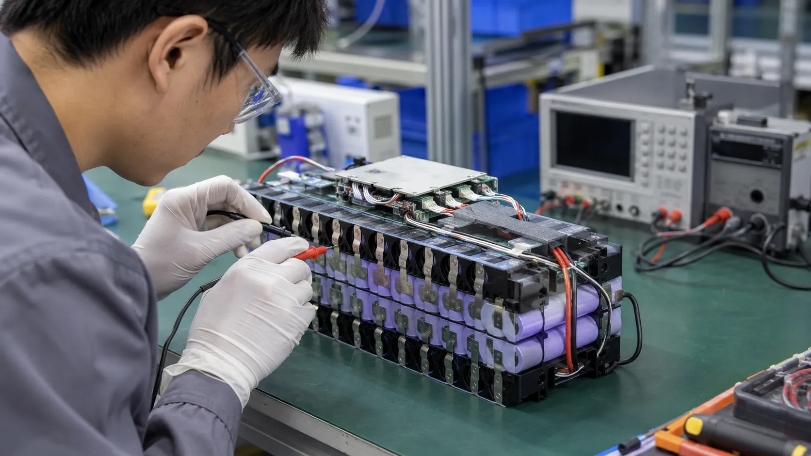
THOR Power supports custom 18650 and 21700 battery pack projects for power tools, portable equipment, lighting, security systems, robotics and industrial applications. Our engineering review starts with the application rather than a preselected catalog pack.
Our project workflow is designed to close the gap between sample success and production stability: requirement review, cell model selection, series-parallel design, PCM/BMS matching, connector and wire confirmation, pack-structure review, sample build, application testing, documentation review and mass-production control.
For approved projects, THOR Power can help define controlled items such as cell model, production lot rules, BMS version, MOSFET rating, NTC value and location, connector, wire gauge, nickel or copper conductor, insulation method, label, packaging and final test items. These controls matter because a pack that looks identical externally can behave differently if one internal component changes.
Before recommending a configuration, we review battery type, voltage, capacity, continuous and peak current, pulse duration, charger, temperature range, available space, connector, wire, PCM/BMS, pack structure, insulation, operating environment, certification needs and production feasibility.
Production quality controls can include cell appearance and batch review, open-circuit-voltage and internal-resistance checks, capacity verification according to project requirements, cell matching, weld inspection, insulation and polarity checks, PCM/BMS function testing, charge-discharge validation, aging and final electrical inspection.
For projects requiring transportation documentation, THOR Power can support UN 38.3 and SDS/MSDS documentation according to the exact battery model and shipment requirements. Market-specific certification scope should be confirmed for the final pack and end product before certification claims are published.
The objective is not to promise that one component can eliminate every risk. It is to build multiple, verifiable safety layers into the cell selection, electrical design, pack structure and manufacturing process from the beginning.
20. When to Involve THOR Power
The best time to involve THOR Power is before the enclosure, charger, connector and certification route are fully locked. Early review gives the project team more freedom to balance runtime, current capability, heat, documentation, cost and long-term supply.
If your product already has a prototype, send the load profile, battery space, charger details, target market and current pack direction. THOR Power can review whether the current design is suitable or whether a safer custom 18650 / 21700 battery pack solution should be considered.
Planning a Custom 18650 or 21700 Battery Pack?
Send us your voltage, capacity, peak current and space constraints. Our engineers will recommend the right cell model, series/parallel configuration and BMS protection — with samples, UN38.3/MSDS support, and stable mass production.
Talk to a Battery EngineerKey Takeaways
- 18650 identifies a cylindrical cell format; it does not guarantee chemistry, current capability, capacity or safety quality.
- Loose, rewrapped, counterfeit and salvaged cells introduce supply-chain and protection risks that cannot be solved by visual inspection alone.
- CID, PTC and vent features are useful internal safety layers, but they do not replace pack-level BMS, fusing, thermal design or validation.
- Torn wraps, damaged top insulators, weak welds and undersized conductors can create short circuits or localized heating even when the cell itself is authentic.
- Cell matching matters in both series and parallel groups because imbalance and unequal current sharing increase stress.
- Cell-to-cell thermal propagation is a pack-level problem. Spacing, barriers, vent paths and enclosure design must be validated as a system.
- UL 1642, IEC 62133-2 and UN 38.3 serve different purposes. Documentation must match the exact model and application.
- The safest custom 18650 battery pack is engineered around the real load, charger, enclosure, environment and long-term production requirements.
Conclusion
18650 cells remain a practical and proven power source for a wide range of products, but their mature format should not be confused with automatic safety. Safe performance depends on the exact cell model, authentic sourcing, disciplined matching, validated welding, electrical protection, insulation, thermal control and correct integration into the final device.
The most important shift for OEM buyers is to evaluate the complete battery architecture. A cell can pass cell-level testing and still be used in an unsafe pack. Conversely, a well-engineered pack can use the strengths of the cylindrical format – mature manufacturing, rigid construction, modular configuration and broad performance options – while reducing foreseeable failure risks.
For custom projects, safety should be reviewed before the voltage, enclosure and charger are locked. Early engineering review gives the development team more freedom to balance runtime, current, dimensions, certification, cost and long-term supply without creating late-stage redesign risk.
THOR Power supports custom 18650 and 21700 battery pack development with application review, cell matching, PCM/BMS integration, connector and structure customization, sample testing and production quality control. The goal is a battery solution that is not only powerful on paper, but also manufacturable, traceable and appropriately protected for its real application.
FAQ: 18650 Battery Safety
Are 18650 batteries safe?
Yes, when authentic cells are used within their specified voltage, current and temperature limits and integrated into a battery pack with suitable electrical, thermal and mechanical protection. The 18650 size alone does not prove that a cell is safe or suitable for a specific device.
Can an 18650 battery explode?
A severely abused or defective cell can vent forcefully, ignite or rupture. Common initiating conditions include overcharge, short circuit, incompatible charging, severe heat, mechanical damage, internal defects and unsafe use of loose or counterfeit cells. Proper pack design reduces the probability and consequence of these failures.
What is the difference between protected and unprotected 18650 cells?
A protected cell has an added external protection circuit and is usually longer. An unprotected cell is a bare industrial component commonly used inside engineered battery packs. Protected cells are not automatically better for OEM packs because pack-level BMS, current requirements and dimensional constraints must be considered.
Does every 18650 cell have a CID and PTC?
No. Many commercial cylindrical cells use a CID, PTC and vent structure, but the exact safety features vary by model and manufacturer. Buyers should verify the cell approval sheet and must not assume features from the 18650 format alone.
Does an 18650 battery pack need a BMS?
Most multi-cell rechargeable 18650 packs need a PCM or BMS appropriate to their series-parallel configuration and application. Typical functions include overcharge, over-discharge, over-current, short-circuit and temperature protection, plus balancing for multi-series packs. The exact design depends on the cell and product.
Can different 18650 brands or capacities be mixed in one pack?
They should not be mixed casually. Different models, capacities, internal resistances, chemistries or ages can create voltage imbalance and unequal current sharing. Production packs should use an approved model with defined matching and traceability criteria.
Is a torn 18650 battery wrap dangerous?
Yes. The cylindrical can is normally negative, and the positive terminal is separated from it by a small insulator. A torn wrap or damaged top ring can allow an unintended short against a device body, holder, busbar or neighboring cell. Damaged cells should not be placed into service.
Can wires or nickel strips be soldered directly to an 18650 cell?
Direct soldering can transfer damaging heat into the cell and is generally avoided for bare production cells. Validated resistance or laser welding is commonly used. Where soldering is required, use manufacturer-approved pre-tabbed cells or a specifically qualified process.
How can buyers identify a fake 18650 battery?
There is no foolproof visual test. Warning signs include impossible capacity claims, inconsistent printing, unusual weight, poor wrappers and uncertain sellers, but authentic sourcing and technical verification are more reliable. OEM projects should use controlled suppliers, model documentation, lot traceability and incoming performance checks.
Is UN 38.3 the same as IEC 62133-2 or UL 1642?
No. UN 38.3 addresses transportation testing. IEC 62133-2 covers safety of portable sealed secondary lithium cells and batteries under intended use and reasonably foreseeable misuse. UL 1642 is a lithium-cell safety standard. Pack and end-product requirements may involve additional standards.
How should an OEM choose a safe 18650 battery pack manufacturer?
Evaluate cell sourcing, engineering review, matching criteria, BMS capability, weld and insulation controls, thermal validation, sample testing, traceability, documentation support, change control and long-term production consistency. Do not evaluate safety only by price, capacity or a generic certificate.
References
- U.S. Consumer Product Safety Commission. Consumer Safety Warning on Loose 18650 Lithium-Ion Cells.
- UL Solutions. Battery Certification Services for Cell Manufacturers.
- International Electrotechnical Commission. IEC 62133-2:2017+A1:2021.
- United Nations Economic Commission for Europe. UN Manual of Tests and Criteria, Revision 8 — Sub-section 38.3.
- NASA NTRS. Limitations of Internal Protective Devices in High-Voltage/High-Capacity Batteries Using Lithium-Ion Cylindrical Commercial Cells.
- U.S. CPSC / Naval Surface Warfare Center. Evaluation of Cell-to-Cell Propagation in Lithium-Ion Batteries Containing 18650 Sized Cells.
- Joshi et al., ACS Energy Letters (2023). Safety and Quality Issues of Counterfeit Lithium-Ion Cells.
- Tam et al., Applied Thermal Engineering (2026). Examining Safe Intervention Windows for 18650 and 21700 Lithium-Ion Batteries under Heat Interruption Experiments.
- Murata. US18650VTC6 Product Datasheet.
- UL Solutions. Battery Safety Testing and Certification.
- NASA. Statistical Characterization of 18650-Format Lithium-Ion Cell Thermal Runaway Energy Distributions.
- U.S. Consumer Product Safety Commission. Overview of Battery Safety Requirements.
- International Electrotechnical Commission. IEC 62619:2022.


Dr. Maximilian Weber is THOR Power's Chief Scientist and a senior expert in lithium battery technology. His technical review focuses on battery safety, performance optimization, energy density and custom battery solution development.
Last technical review: July 2026

Victor Xiong holds a Master's degree from The Chinese University of Hong Kong, Shenzhen. He leads THOR Power's OEM Division and focuses on custom battery solutions for global device brands, product developers and industrial customers.